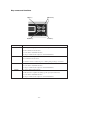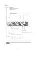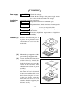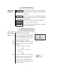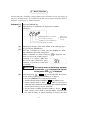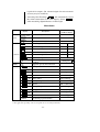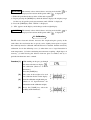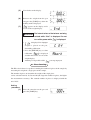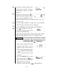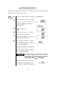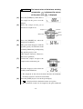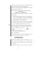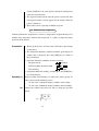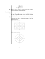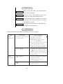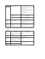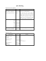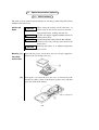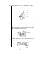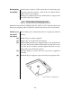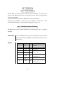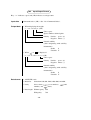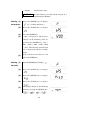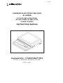
1
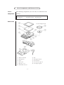
M054-E109 SHIMADZU ELECTRONIC BALANCE EL SERIES EL120, EL200, EL300, EL600, EL1200, EL2000, EL3000, EL12K, EL600S, EL6000S INSTRUCTION MANUAL TESTING & WEIGHING EQUIPMENT DIVISION M054-E084 SHIMADZU ELECTRONIC BALANCE EL SERIES EL120, EL200, EL300, EL600, EL1200, EL2000, EL3000, EL12K, EL600S, EL6000S INSTRUCTION MANUAL READ THIS MANUAL THOROUGHLY TO ENSURE CORRECT USE OF THE EQUIPMENT. SAVE THIS FOR REFERENCE IN USE. TESTING & WEIGHING EQUIPMENT DIVISION Safety Precautions NOTICE Precautions in this instruction manual are defined as follows. CAUTION NOTICE Failing to observe this may result in light to medium levels of injury or physical damage. Information for the correct use of the equipment. Follow the cautions below for safe and proper use of the EL balance. CAUTION Do not use the EL balance in dangerous areas∗. Use only the AC adapter that is provided by the distributor who is authorized by Shimadzu Corporation. Use options and peripherals provided by Shimadzu. Use of inadequate attachments and peripherals may cause malfunction of the balance. The EL balance is a precision instrument. Take enough care and precautions when handling it to ensure proper operation over a long period of time. ∗ Places exposed to flammable gases, liquids or dust. INTRODUCTION Thank you for purchasing the Shimadzu EL Series Electronic Balance. Before using the balance, read this Instruction Manual carefully and store it for reference in use. CONTENTS 1. List of Components and Names of Units..................................................... 1 2. Installation ................................................................................................... 4 3. Cautions and Notes ...................................................................................... 5 4. Measurement Procedure .............................................................................. 5 5. Menu Selection ............................................................................................ 7 6. Registration of Units.................................................................................... 9 6.1 Conditions for Registration ..................................................................... 9 6.2 Registration Procedures ........................................................................... 9 6.3 Deleting the Registration ......................................................................... 9 7. Calibration ................................................................................................... 10 8. Piece Counting............................................................................................. 10 9. Percentage Conversion ................................................................................ 13 10. Specific Gravity Measurement .................................................................... 14 11. Switching Units ........................................................................................... 16 12. Performance Inspection ............................................................................... 17 13. Maintenance................................................................................................. 19 14. Malfunction?................................................................................................ 19 15. Specifications............................................................................................... 21 16. Parts List ...................................................................................................... 23 17. Special Accessories (Options) ..................................................................... 24 17.1 Built-in Battery ........................................................................................ 24 17.2 Below-Balance-Weighing Hook .............................................................. 26 18. Peripherals ................................................................................................... 27 18.1 Printer EP-60A ........................................................................................ 27 18.2 RS-232C Interface IFB-102A.................................................................. 27 18.3 Input/Output Format ................................................................................ 28 18.4 Command Codes...................................................................................... 30 1. List of Components and Names of Units List of The following components (one for each) are contained in the components package. Balance main unit AC adapter Protective cover Pan supporter Instruction manual Operating guide Pan Names of units For the small-pan model q Balance main unit w Pan e Pan supporter r Pan supporter shaft t Level y Power switch u Power jack i Level screws (3 places) o Protective cover !0 AC adapter (option) !1 DATA I/O connector -1- Key names and functions UNIT key BREAK key MODE key TARE key Name of Key BREAK Function 1) Changes the display from “oFF” to the weight. 2) Discontinues menu selection. 3) Cancels the Auto Print function. 4) Stops continuous data output to external instruments. TARE 1) Subtracts the weight of the container. 2) Confirms menu selections. 3) Sets the reference values for piece counting and percentage conversion. UNIT 1) Switches the units. 2) Cancels the Auto Print function. 3) Stops continuous data output to external instruments. MODE 1) Selects different menu items. 2) Measures the weight in air during specific gravity measurement. 3) Cancels the Auto Print function. 4) Stops continuous data output to external instruments. -2- Display Auto Print mark: Illuminates when the Auto Print function is turned on: Low Battery mark: Illuminates when the built-in battery (optional) needs recharging. Percentage mark Turn the power switch off immediately if this mark illuminates. Piece counting mark Negative sign mark Gram mark Specific gravity measurement mark Stability mark: Illuminates when the display stabilizes. Center Zero mark: Illuminates when the display stabilizes within 0 ± 0.25 of the minimal increment. Not applicable depending on the local regulations for measuring instruments. -3- 2. Installation Power suppy Installation location Check the voltage. Check that the voltage of the power supply meets the voltage indicated on the AC adapter. Avoid the following conditions: CAUTION CAUTION Exposure to corrosive or flammable gases. NOTICE Exposure to dust, wind, vibrations, electromagnetic NOTICE NOTICE waves and magnetic fields. Exposure to direct sunlight, remarkable temperature fluctuations. Extremely high/low temperatures or high/low humidity. Installation (1) Remove the protection paper at 4 places on the protective cover and mount the cover over the main unit. (2) Mount the pan supporter and the pan on the pan supporter shaft. Assure the horizontal installation of the balance by rotating the level screw until the air bubble in the level comes to a rest in the center of the red circle. (Also check that the balance is placed steadily.) For quick adjustment, screw in the front left level screw until it does not touch the table. Level the balance using the 2 screws at the rear. Finally, adjust the front left level screw so that it touches the table supporting the balance steadily. (3) -4- 3. Cautions and Notes Observe the following: CAUTION Use only the AC adapter that is provided by the distributor who is authorized by Shimadzu Corporation. NOTICE NOTICE Make sure that any foreign objects, including water and metal pieces, do not enter the interior of the balance. Do not leave the balance with objects on the pan. NOTICE Do not cause a shock to the pan. NOTICE Do not recharge the built-in battery (optional) for more than 15 hours. 4. Measurement Procedure The procedures are explained using the EL300 as an example. Turn on the [When using the AC adapter] power Set the power switch to OFF and insert (1) the AC adapter plug into the power jack of the balance. Plug the AC adapter into the power outlet. (2) Check that nothing is placed on the pan. (3) Slide the power switch to the ON position. • When using the AC adapter ON1 • When using the optional built -in battery ON2 (4) The Check display will illuminate, indicating that the temperature sensor inside the balance is being checked. Depending on the ambient temperature, this may remain illuminating for about 30 seconds. -5- (5) (6) (7) (8) Measurement (1) (2) ∗Container: *Preliminary loading: Turn off the power The all segments illuminate for approximately 6 seconds. is displayed. Press the [BREAK] key. Zero is displayed. The zero may be unstable immediately after the power is turned on. Allow the balance to warm up for more than 5 minutes. To conduct accurate measurements, a warm up time of over 30 minutes is recommended. Calibrate sensitivity (refer to “7. Calibration”). Place the container∗ on the center of the pan and press the [TARE] key. Check that the Center Zero mark illuminates. Load the sample and read the displayed value when the display stabilizes. To conduct accurate measurements, perform a preliminary loading∗ before conducting measurements. will be displayed if the weight of the sample exceeds the capacity, or the combined weight of the sample and container exceeds the total available range of the balance. Any container in which the sample is placed. Measurements without any container are also possible. “Preliminary loading” refers to loading and unloading the sample or the weight once before conducting the actual measurement. A preliminary loading improves the accuracy of the measurement. Slide the power switch to the OFF position. CAUTION Be sure to turn off the power when the balance is not to be used for a long period of time. -6- 5. Menu Selection Various functions, including selecting different measurement speeds and setting of the piece counting mode, are available on the EL-series balance. Selection of these functions is referred to as “Menu Selection”. Procedure (1) (2) Press the [MODE] key. The currently set conditions are displayed in symbols. (Example) Adds parity to the data output∗ Zero tracking activated∗ Stability detection width: Large Normal Response Mode (3) (4) The display changes in the order shown in the table on page 8 by pressing the [MODE] key. To select a condition or a mode, press the [TARE] key while the condition or the mode is displayed. When a condition or a mode is selected, is displayed, and then it reverts to the weight (or piece counting or %) display. (This does not occur when calibration, piece counting, or percentage conversion is selected.) CAUTION (5) (Items with“ ∗” → illuminates when → set to on.) The internal values of the balance are being revised while is displayed. Do not turn off the power while is displayed. After displaying ( k g for the EL12K), the balance reverts to the weight (or piece counting or %) display. • Press the [BREAK] key to stop menu selection. • Set the response mode to “Normal” ( ) in ordinary cases. • Set the response mode to “Fast” ( ) when it is necessary to reduce the time required for measurements. (Be acknowledged that measurement accuracy may be sacrificed). • Set the internal stability detection width to “Large” ( ) when external causes such as vibration hinder smooth output for Auto Printing, or when intending to reduce the time -7- required for output. (Be acknowledged that measurement accuracy may be sacrificed.) • Activating Zero Tracking ( ) will automatically cancel the minor fluctuation in the zero display. Select when measuring slight differences of the weight. Menu Items Display Mode Symbol for conditions display Description PCS Piece counting % Percentage conversion Calibration Fast Response Mode Normal Response Mode Internal stability detection width: Small Internal stability detection width: Large Zero tracking: ON Conditions Zero tracking: OFF RS-232C communication specification settings Specific gravity measurement Mode ∗1 kg No display With parity: Kilogram g Gram ct Carat 1ct = 0.2g ∗ oz Ounce 1oz = 28.3495g ∗2 ozt Troy ounce 1oztv31.1035g ∗ dwt Penny weight 1dwt = 1.55517g ∗2 GN Grain 1GN = 0.0647989g 2 2 ∗ H tl Hong Kong tael 1tl = 37.429g ∗2 S tl Singapore tael 1tl = 37.7994g ∗ t tl Taiwan tale 1tl = 37.5g Momme 1mo = 3.75g 2 2 ∗2 CLEAr mo Canceling registered units ∗1 EL12K only ∗2 Not applicable depending on the local regulations for measuring instruments. -8- 6. Registration of Units Three units can be registered in addition to “gram”. The registered units remain after the power has been turned off. Registered units can be selected by pressing the [UNIT] key. 6.1 Conditions for Registration • Up to three units (including piece counting, % and specific gravity) can be registered in addition to “gram”. • When a new unit is added after three units have been registered, the firstregistered unit is deleted and the new unit is added. 6.2 Registration Procedures 1) Repeat pressing the [MODE] key while the balance displays the weight (except for the case of specific gravity measurement) until “ xx” is displayed. 2) Press the [TARE] key when the desired unit is displayed. “→” is displayed for already registered units. 3) appears on the display and it changes to the weight display with the newly registered unit. CAUTION The internal values of the balance are being revised while displayed. Do not turn off the power while is is displayed. 6.3 Deleting the Registration • Follow the procedure below to delete registered units one by one. (Piece counting and % cannot be deleted by this method.) 1) Repeat pressing the [MODE] key while the balance displays the weight (except for the case of specific gravity measurement) until “ xx” is displayed. 2) Repeat pressing the [MODE] key until the unit to delete is displayed. “→” is displayed for already registered units. 3) Press the [TARE] key when the unit to delete is displayed. 4) appears on the display and it changes to the weight display. -9- CAUTION The internal values of the balance are being revised while displayed. Do not turn off the power while • is is displayed. Follow the procedure below to delete all the units registered. 1) Repeat pressing the [MODE] key while the balance displays the weight (except for the case of specific gravity measurement) until “CLEAr” is displayed. 2) Press the [TARE] key while “CLEAr” is displayed. 3) “SEt” appears on the display and it changes to the weight display. CAUTION The internal values of the balance are being revised while displayed. Do not turn off the power while is is displayed. 7. Calibration The EL-series electronic balance measures the weight using the gravity of the earth. Since the acceleration due to gravity varies slightly from region to region, the sensitivity must be calibrated when the balance is installed. Perform sensitivity calibration also in the following cases: (1) when there was a large fluctuation in room temperature, (2) before conducting measurements requiring a high degree of accuracy, (3) when moving the balance from one place to another, and (4) as periodical maintenance once a month. Procedure (1) With nothing on the pan, go through the menu selections to display for calibration. (Refer to “5. Menu Selection”.) Press the [TARE] key. (2) The value of the weight to be used for calibration flashes on the display. (3) Place the calibration weight on the pan. (Refer to “15. Specifications” for information on the calibration weight.) (4) Press the [TARE] key when the stability mark illuminates. - 10 - (5) Zero flashes on the display. (6) Remove the weight from the pan and press the [TARE] key when the stability mark is displayed. (7) appears on the display and it reverts to the weight display. CAUTION The internal values of the balance are being revised while “End” is displayed. Do not turn off the power while • is displayed. is displayed if an improper weight is placed on the pan, disenabling calibration. • Press the [BREAK] key to abort calibration. is displayed and then the balance reverts to the weight display. Aborting is not possible while is being displayed. 8. Piece Counting The EL-series balance is capable of counting the number of pieces of the sample by measuring the weight of a single piece of the sample. The number of pieces to determine the weight of the single piece can be selected from 10, 20, 50 and 100 (the larger the number of pieces, the higher the measurement accuracy). The counted number of pieces is displayed with the unit “PCS”. Setting procedure (1) Place the container on the pan and press the [TARE] key. - 11 - (2) Select piece counting mode (Conv PCS) in menu selection, and press the [TARE] key. (Refer to “5. Menu Selection”.) (3) The number of reference pieces is displayed. Select the intended number by pressing the [MODE] key. The displayed number changes in the following order: 10 → 20 → 50 → 100 → 10... (4) Place the displayed number of sample pieces in the container while the number of reference pieces is displayed. (5) Press the [TARE] key when the stability mark illuminates. (6) After is displayed, it changes to the piece counting display with the “PCS” mark illuminating. At the same time, the reference weight and the “PCS” unit are registered on the [UNIT] key. (Refer to “11. Switching Units”). CAUTION The internal values of the balance are being revised while is displayed. Do not turn off the power while • is displayed. If the sample weight exceeds the capacity of the balance, or the weight of a piece of the sample is smaller than the minimum increment, is displayed and the display reverts to the unit before menu selection. • Press the [BREAK] key to abort piece counting settings. “ ” is displayed and then it reverts to the display before menu selection. Aborting is not possible while - 12 - is being displayed. 9. Percentage Conversion The EL-series balance is capable of calculating and displaying the sample percentage to the reference set as 100%. Setting (1) procedure (2) Place the container on the pan and press the [TARE] key. Select percentage conversion mode ( %) in menu selection, and press the [TARE] key. (Refer to “5. Menu Selection”.) (3) (4) is displayed. Place the sample to be used as reference in the container. (5) Press the [TARE] key when the stability mark illuminates. (6) After is displayed, it changes to the percentage display with the “%” mark illuminating. At the same time, the reference weight and the “%” unit are registered on the [UNIT] key. (Refer to “11. Switching Units”) CAUTION The internal values of the balance are being revised while off the power while • If the sample weight exceeds the capacity of the balance, or it is smaller than 100 times the minimum - 13 - is displayed. Do not turn is displayed. increment, is displayed and the display reverts to the unit before menu selection. • Press the [BREAK] key to abort piece counting settings. is displayed and then it reverts to the display before menu selection. Aborting is not possible while • is being displayed. % will be displayed with the following number of digits depending on the weight of the reference sample. Less than 1000 times the minimum increment No decimals Less than 10000 times the minimum increment To the 1st decimal place More than 10000 times the minimum increment To the 2nd decimal place 10. Specific Gravity Measurement The EL-series balance allows easy measurements of the specific gravity of a sample by measuring its weight in air and in water (with the specific gravity of water taken to be one). The optional below-balance-weighing hook facilitates the measurement in water. Described below is the procedure when using the below-balance-weighing hook. (See “17.2 Below-Balance-Weighing Hook”.) The optional “Specific Gravity Measurement Set” is also available. The weight in air during specific gravity measurement is displayed as grams. Procedure (1) Select specific gravity measurement mode in menu selection. (Refer to “5. Menu Selection”.) (2) Press the [TARE] key. is displayed and then “g” and the specific gravity measurement mark (▼) illuminate. - 14 - CAUTION The internal values of the balance are being revised while off the power while (3) is displayed. Do not turn is displayed. Press the [TARE] key when there is no sample on the pan to zero the display. (4) Place the sample on the pan to measure its weight in air. Sample Balance Base Water tank (5) Underwater pan Press the [MODE] key when the display has stabilized. (6) The gram mark disappears with the specific gravity measurement mark remaining illuminating and displaying the specific gravity value. (The display fluctuates. However, this is not a problem.) (7) Unload the sample and place the sample on the underwater pan. (8) Read the displayed value when the stability mark illuminates. • The weight in air has to be more than 100 times the minimum increment to ensure accurate measurements. (9) Press the [UNIT] key to revert to the gram display. • is displayed if the calculation results are negative. • The calculation results can be output by the print command - 15 - while the results are being displayed. (Continuous output is not possible during specific gravity measurement.) • Return to step (3) by pressing the [MODE] key to continue specific gravity measurements. • The specific gravity is calculated using the following equation. (Weight in Air) (Weight in Air) − (Weight in Water) ――――――――――――――――― • To stop specific gravity measurement and revert to weight measurement... (a) While displaying specific gravity value (while displaying “▼”) : press the [MODE] key and then press the [UNIT] key. (b) While displaying weight in specific gravity mode (while displaying “▼g”): press the [UNIT] key. • The specific gravity measurement is registered for the [UNIT] key. Specific gravity measurement can be started from step (3) by pressing the [UNIT] key during weight measurement. (10) To cancel specific gravity measurement, follow the procedure below. • Press the [UNIT] key to display another unit (g, PCS, or %). • Press the [MODE] key to display “ • ”. The stability mark illuminates if specific gravity measurement has been set. • Press the [TARE] key. This cancels the specific gravity measurement, and the balance displays ordinary units such as g, PCS and %. 11. Switching Units • Pressing the [UNIT] key switches the unit between “g” and other registered units. (The balance may be shipped from the factory with no units registered. In this case, the unit cannot be switched.) • When piece counting or percentage conversion is registered - 16 - for the [UNIT] key, the value will be calculated and displayed using the latest reference. • The registered units remain after the power is turned off. The unit registered most recently appears on the display when the power is turned on. • Three units can be registered in addition to grams. 12. Performance Inspection Conduct performance inspection in a room at a temperature of approximately 25°C without large fluctuation. Perform this inspection as a guide to judge the proper operation of the balance. Preparation • Warm up the balance for more than 30 minutes after turning on the power. • The inspection should be conducted with the gram display. If another unit is displayed, press the [UNIT] key to switch to the gram display. • Select the following conditions in menu selection. Response mode (Normal) Internal stability detection width or Zero tracking • (off) Perform preliminarily loading, and then press the [TARE] key to zero the display. Repeatability (1) Repeat loading and unloading a weight close to the capacity 10 times and record the following values. Xi: the value at which the display stabilizes after loading Yi: the value at which the display stabilizes after unloading (2) Obtain the standard deviation σx and σy using the equation below. - 17 - (3) Both σx and σy should be within 1.5 times the standard deviation indicated in “15. Specifications”. Cornerload error (1) Load a weight of approximately 1/4th the weighing capacity in the order of the numbers in the diagram below and record the values X1 to X5. (2) The differences between the value at the center of the pan (X1) and other values (X2 to X5) should be within 3 times the minimum increment. In the case of a square pan In the case of a round pan - 18 - 13. Maintenance Wipe any dirt away with a soft cloth moistened NOTICE with a neutral detergent. Organic solvents and chemical dusters will NOTICE damage the coating and membrane panel. Use the protective cover (supplied as a standard NOTICE accessory) when using the balance in places where dirt may attach. The pan can be washed in water. Be sure that it NOTICE is completely dry when using. 14. Malfunction? Check the following items before contacting our service personnel. When Before Phenomenon Cause and Solution • Nothing is displayed after the measurement • AC adapter is not connected. • Switchboard is turned off. power is turned on. • Built-in battery (optional) is empty. ⇒ See “17.1 Built-in Battery”. • The power switch is set to position “ON2” when using the AC adapter. • The power switch is set to position “ON1” when using the built-in battery. • Stops at • Depending on the ambient temperature, may be displayed for about 1 minute. If “CHE t” remains displayed for more than 1 minute, contact our service personnel. During • • An object heavier than the capacity has is displayed. been placed on the pan. measurement • Sensitivity (span) is not correct. ⇒ See “7. Calibration”. • • The pan and/or pan supporter is not is displayed. mounted correctly. - 19 - When During Phenomenon Cause and Solution • The display fluctuates. • Affection of vibration or wind. ⇒ Install the balance at a place without measurement vibration or wind. ⇒ Set the response speed to normal. • Affection of electromagnetic waves or electrical noise. ⇒ Place the balance away from the noise source. • The Low Battery mark remains • Unexpectedly turns to • The built-in battery (optional) is empty. ⇒ See “17.1 Built-in Battery”. illuminated. . • There was a momentary power failure. ⇒ Press the [BREAK] key. During piece counting • Number of pieces cannot be counted correctly. • There is a large variation in the weight between pieces of the sample. ⇒ Increase the number of the reference sample pieces. During specific gravity • The specific gravity value fluctuates. • The weight of the sample is too small for the specific gravity. measurement If the following codes display during operation, solve the problem by applying the solution below. Code Description Solution This appears when an improper weight is placed on the pan during calibration. Restart calibration with the correct weight. This appears when trying to start calibration with an object on the pan. Restart calibration after removing the object from the pan. This appears when the reference value is smaller than the minimum increment in piece counting or percentage conversion mode. Reset the reference with a larger amount of sample. Internal temperature sensor error. Stop using the balance and contact our service personnel. Internal computation error. - 20 - 15. Specifications Model EL120 EL200 EL300 EL600 EL1200 Weighing capacity 120g 200g 300g 600g 1200g Minimum display 0.01g 0.01g 0.01g 0.05g 0.1g Standard deviation σ ≤ 0.01g σ ≤ 0.01g σ ≤ 0.01g σ ≤ 0.05g σ ≤ 0.1g ± 0.01g ± 0.01g ± 0.02g ± 0.05g ± 0.1g 100g 200g 300g 500g 1000g Linearity errors Calibration weight φ110 Pan size (mm) Stability of Sensitivity (5 ~ 35 C˚) ± 20ppm/°C 170 × 130 ± 15ppm/°C Dimensions of main ± 20ppm/°C ± 20ppm/°C Approx. 185(W)× 215(D)× 55(H) body (mm) Weight (kg) Approx. 1.25 Temperature range Power supply ± 10ppm/°C 5 to 40°C DC output voltage: 12 to 19 VDC or (AC adapter : option) 14 to 19 VDC (with the battery charge function) DC output current: Reference 80mAdc/16V or 100mAdc/15V Shape of the plug: - 21 - Model EL2000 EL3000 EL12K EL600S EL6000S Weighing capacity 2000g 3000g 12kg 600g 6000g Minimum display 0.1g 0.1g 1g 0.1g 1g Standard deviation σ ≤ 0.1g σ ≤ 0.1g σ ≤ 1g σ ≤ 0.1g σ ≤ 1g Linearity errors ± 0.1g ± 0.2g ± 1g ± 0.1g ± 1g Calibration weight 2000g 3000g 10kg 500g 5000g ± 20ppm/°C ± 20ppm/°C 170 × 130 Pan size (mm) Stability of Sensitivity (5 ~ 35 C˚) ± 15ppm/°C ± 10ppm/°C Dimensions of main Approx. 185(W)× 215(D)× 55(H) body (mm) Weight (kg) Approx. 1.25 Temperature range Power supply ± 20ppm/°C 5 to 40°C DC output voltage: 12 to 19 VDC or (AC adapter : option) 14 to 19 VDC (with the battery charge function) DC output current: Reference 80mAdc/16V or 100mAdc/15V Shape of the plug: - 22 - 16. Parts List Special Accessories (Options) Product Name P/N Remarks Built-in battery 321-60063 Below-balance weighing hook 321-34532-03 Cannot be used with the EL12K. Specific gravity measurement set 321-42253 Use with a balance whose capacity is 600g or more (the measurable weight is reduced by 200g). This set allows specific gravity measurement of samples with a volume of 5 to 500cm3 (the size of the sample must be smaller than 115mm in diameter × 70mm in height). Calibration weight 100g 321-53445-10 200g 321-53446-10 500g 321-53447-10 1kg 321-53448-10 2kg 321-53449-10 5kg 321-53450-10 10kg 321-53451-10 Printer, EP-60A 321-42008-10 For heat-sensitive paper RS-232C interface, IFB-102A 321-41167-10 Maintenance Parts Product Name P/N Remarks Square pan 321-41419 Pan supporter, square 321-41394-90 Round pan 321-41418-10 Pan supporter, round 321-40910-90 Protective cover 321-41617-01 1 piece 321-41617-70 Contains 10 pieces Level adjusting feet 321-41397 Rubber feet 321-53530-30 Battery label 321-42019 - 23 - 17. Special Accessories (Options) 17.1 Built-in Battery The battery can be used for about 12 hours on one charge (when using the balance without external devices). Caution and Notes NOTICE CAUTION NOTICE NOTICE When using the battery for the first time, or when using it after it has not been used for a long period of time, recharge it before use. Use the AC adapter supplied with the balance to recharge the battery. Do not recharge the battery for more than 15 hours. (Unnecessary long recharge will shorten the battery life.) Recharge the battery at an ambient temperature of 5 to 35°C. Mounting (1) the battery into the balance Turn off the power and remove the pan and pan supporter. Unscrew the case fixing screw (13). (2) Lift up the case from the rear (the case is connected to the balance by cables), rotate it 180 degrees to turn it over, and then place it in front of the balance. Battery compartment - 24 - (3) Fix the sponge (14), battery (15), and holder plate (16) into the battery compartment and fix them using the fixing screws (17). Ensure that both the left and right sides of the sponge (14) are slightly bent. Tighten the screws completely! Battery compartment Cables should be at the front. (4) Insert the connector at the tip of the battery cords into the 2 pin connector on the board. Remount the case by reversing the removing procedure, and fix it with the screw. When remounting the case, take care so that the switch cables (18) are not caught between the case panels. 2 pin connector (5) Apply the “Battery Built-in” label on the front of the balance at the right bottom. Label - 25 - Recharging the battery Set the power switch to “OFF”. Insert the AC adapter plug into the power jack of the balance, and insert the AC adapter into the power outlet to start recharge. Recharge is completed in 15 hours. Pull out the AC adapter from the power outlet after 15 hours. 17.2 Below-Balance-Weighing Hook With the below-balance-weighing hook, the sample can be suspended below the balance for weighing. This is particularly useful for specific gravity measurements. Attaching (1) the hook to the balance Turn off the power and disconnect the AC adapter plug from the balance. (2) (3) (4) Remove the pan and pan supporter. Remove the seal on the back of the balance. While holding down the pan supporter shaft, screw the hook into the screw hole on the bottom of the balance by hand. (Do not use any tools such as a monkey wrench to tighten the hook, as it may damage the sensor inside the balance.) Place the balance at a place where no excess force is applied to the hook. Remount the pan supporter and pan onto the pan supporter shaft. (5) (6) Below-balance-weighing hook - 26 - 18. 18.1 Peripherals Printer EP-60A The EP-60A is a thermal printer connected to the DATA I/O connector of the balance. The EP-60A prints the data displayed on the balance and performs statistical calculations. See the instruction manual for the EP-60A for detailed information. Before using the EP-60A, set the baud rate to 1200bps and stop bit to 1. (See “Selecting the Baud Rate” and “Selecting the Stop Bit” on page 27.) 18.2 RS-232C Interface IFB-102A The IFB-102A is used to connect the balance to external devices such as a personal computer. Connection After confirming that the power of the balance has been turned off, insert the plug of the IFB-102A into the DATA I/O connector of the balance. Signals Pin No. Signal Name I/O Description Ground 1 FG 2 TXD Out Data output 3 RXD In Data input 4 RTS 5 CTS 6 DSR 7 SG 20 DTR Short circuit Communication possible In with polarity (+) Communication impossible - 27 - Out with polarity (−) 18.3 Input/Output Format Key: “△ ” indicates a space and (CR) indicates a carriage return. Input data Command code + (CR) ⇒ See “18.4 Command Codes”. Output data • When displaying the weight S−△△300.00g△ (CR) Unit + space Space, number, decimal point Polarity Positive space (△) Negative minus (−) Internal stability (when outputting with stability information) Stable S Unstable U • When or is displayed S − △ △ △ △ oL △ △ △ △ (CR) Unit + space Polarity Positive space (△) Negative minus (−) Internal stability (when outputting with stability information) Stable S Unstable U Data format • ASCII (JIS) code • Baud rate Select from 300, 600, 1200, 2400, 4800, and 9600. • Parity Select from (even number), number), and (none). • Data length Without parity 8 bit With parity - 28 - 7 bit (odd • Stop bit Select from 1 and 2. NOTICE Set the baud rate to 1200 and the stop bit to 1 when using the EP-60A. Selecting (1) Press the [MODE] key to display the baud rate (see “5. Menu Selection”). (2) Press the [TARE] key to display . (3) Press the [TARE] key. (4) “300” is displayed. The display changes in the following order by pressing the [MODE] key: 300 → 600 → 1200 → 2400 → 4800 →9600 → 300... The currently selected baud rate is displayed with the stability mark. (5) Select the desired baud rate and press the [TARE] key. Selecting (1) Press the [MODE] key to display . the parity (2) Press the [TARE] key to display . (3) Press the [MODE] key to display . (4) Press the [TARE] key to display “ (5) ”. The display changes in the following order by pressing the [MODE] key: → → → - 29 - ... The currently selected parity is displayed with the stability mark. (6) Select the desired parity and press the [TARE] key. ∗ The data length becomes 7 bits if “ ” or “ ” is selected for the parity. Selecting (1) the stop bit (2) Press the [MODE] key to display . Press the [TARE] key to display . (3) Press the [MODE] key to display . (4) Press the [TARE] key to display . The display changes in the following (5) order by pressing the [MODE] key: 1 → 2 → 1... The currently selected stop bit is displayed with the stability mark. (6) Select the desired stop bit and press the [TARE] key. 18.4 Command Codes Shown below are commands available when the balance is connected to external devices such as a personal computer. See “18.3 Input/Output Format” for information on data formats. Inputting characters or control codes that are not listed below may impede the proper operation of the balance or the performance of correct measurements. When connecting the balance to external devices to conduct unattended operation, take appropriate precautionary measures against unexpected communication failure (setting a waiting time for input, for example). - 30 - Command code Q Function Start operation Description Switches the display from to weight when the power is turned on. Stops Auto Print and continuous output. T Subtraction of the container Zeros the display. weight D05 Print (once) Outputs the displayed data. D06 Auto Print∗ Outputs the displayed data automatically when the display stabilizes after an object is placed on the pan while zero is displayed. D01 Continuous output ∗ Outputs the displayed data continuously at an interval of approx. 100ms. D09 Output stop Stops Auto Print and continuous output. D07 Single output with stability Outputs the data once with the internal stability information information. Continuous output with stability information∗ Outputs the data continuously with the internal D03 stability information. Commands with “∗” are cancelled by pressing the [BREAK], [UNIT], or [MODE] key. - 31 - TOKYO OFFICE 3, Kanda-Nishikicho 1-chome, Chiyoda-ku, Tokyo 101-8448, Japan Phone: 81(3)3219-5641 Fax: 81(3)3219-5710 Cable Add.:SHIMADZU TOKYO Overseas Telex No. : 0232-3291 (SHMDT J) KYOTO OFFICE 1, Nishinokyo-Kuwabaracho, Nakagyo-ku, 604-8511 Japan Phone: 81(75)823-1200 Fax: 81(75)812-3438 Cable Add.:SHIMADZU KYOTO Overseas Telex No. : 05422-166 (SHMDS J) SHIMADZU DEUTSCHLAND GmbH Albert-Halm-Strasse 6-10, D-47269 Duisburg, F. R. Germany Phone: 49(203)7687-0 Fax: 49(203)7666-25 SHIMADZU (ASIA PACIFIC) PTE LTD. 16 Science Park Drive #01-01 The Pasteur Singapore Science Park, Singapore 118227, Republic of Singapore Phone: 65-778-6280 Fax: 65-779-2935 SHIMADZU DO BRASIL COMERCIO LTDA. Rua Cenno Sbrighi 25, CEP 05036-010 Agua Branca Sao Paulo, Brasil Phone: 55(11)861-1688 Fax: 55(11)861-2209 Beijing Shimadzu Scientific Instrument and Equipment Center 5F, INSTEC-Commercial Bldg, B-19 Beisanhuanzhong Lu, Xicheng Ou, Beijing, 100029, The people’s Republic of China Phone: 86(10)6204-3953 Fax: 86(10)6204-3988 SHIMADZU SCIENTIFIC INSTRUMENTS INC 7102, Riverwood Drive, Columbia, Maryland 21046, USA Phone: 1(410)381-1227 Fax: 1(410)381-1222 4500-02200-600TD (368)