1
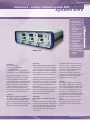
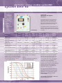
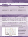
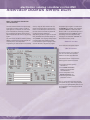
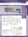
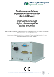
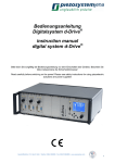
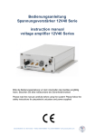
electronics • analog • modular system ENV
system ENV
ENT 400
casings for system ENT, ENV, EDA
width
part no.
42 TE casing
42 TE
E-103-97
42 TE casing with cooling*
42 TE
E-103-951
63 TE casing
63 TE
E-103-90
63 TE casing with cooling*
63 TE
E-103-901
84 TE casing
84 TE
E-103-91
84 TE casing with cooling*
84 TE
E-103-911
84 TE rack casing**
84 TE
E-103-92
84 TE rack casing 375mm**
84 TE
E-103-921
2 x 84 TE
E-103-94
84 TE double high casing*
ENV casings
rack
mounting
angles
rack casing
dimensions
unit
42 TE
63 TE
84 TE
84 TE rack
84 TE rack
84 TE double high
width
mm
265
373
480
483
483
480
depth
mm
343
343
343
272
375
343
height
mm
158
158
158
133
133
290
1 TE = 5.08 mm
* casings with active cooling are necessary for high power amplifiers when using more than one ENV 300 or at least one ENV 800 systems.
We strongly recommend active cooling if the output current of all ENV modules is beyond 300mA.
** rack mounting angles available upon request
ENT system · main supply modules ENT 40/20, ENT 400
ENT 40/20
ENT 40/20
ENT 400
main voltage
module width
output power
supply frequency
part no.
230V
14TE
25W
50/60Hz
E-103-13
115V
14TE
25W
50/60Hz
E-103-14
115V/230V
18TE
100W
50/60Hz
E-103-33
The main supply module ENT 40/20 can be operated with up to four modules ENV 40, but no module ENV 300.
The main supply module ENT 400 can be operated with up to two modules ENV 300 or one module ENV 800
72 www.piezojena.com
modular system ENV
modular system ENV
table top
OEM piezo-amplifier
electronics • analog • modular system ENV
system ENV
■
■
■
■
■
■
■
ENV system
modular power
supply system for
piezo electrical
elements
different currents
for optimum
solutions
each channel with
separate display
closed loop module for measurement systems
module for PC
connection
excellent signalto-noise ratio
protection circuit
for power supply
and piezoelements
applications
■ multi-axes actuator
■
■
■
high frequency applications
(ENV 300 and above)
automated processes in engineering
precision alignment in optical applications
The amplifier system ENV is a modular
system with a 19” casing. In special appli cations it is possible to combine one or
more amplifier modules with different characteristics. Each amplifier module has its own
display which shows the output voltage.
If used with a measurement system and
closed loop module, it displays the calibrated motion. Different modules for closed
loop and PC connections are available.
system 40 –
adjustment with highest resolution
The amplifier system 40 was developed for
static and low frequency applications. The
system has very low noise characteristics
(typ. 0.3 mVRMS @500 Hz) and thus provi des
resolutions in the nm and sub nm range.
system 300 –
flexible system for higher dynamic work
The amplifier system 300 was developed for
dynamic applications of piezoelectrical ele-
The amplifier system 800 delivers current
of 800mA. A monitor output gives the equivalent output voltage. Please find advice
for dynamic work with piezoelectrical ele-
ments. For example, it allows the use of the
PZ 100 positioning system with frequencies
of approximately 500Hz at full amplitude.
ments in the chapter “piezoline”.
The amplifier series ENV 800 has been
complemented with the series CLE systems
so they can be used with actuators with
inte grated measurement systems.
The system was designed using a modern
electronic concept to reach the same noise
characteristics of the system 40. This allows
the system 300 to be used in dynamic applications for positioning purposes with very
high resolution.
The amplifier series ENV 300 has been complemented with the series CLE systems so
they can be used with actuators with integrated measurement systems.
system 800 –
high dynamic work for high load actuators
The amplifier system 800 is perfectly suited
for high dynamic applications. Multi-layer low
voltage actuators have a high capac tiance.
For dynamic work, it is necessary to charge
and discharge this capacitance with high
stady currents.
assembly
Each amplifier system consists of at least
two modules. The ENT module supplies the
main voltages for the ENV amplifier module,
which is the actual amplifier. The ENT and
ENV modules should be placed in a casing.
The casing can be delivered as a 19” rack
mount. Depending on the application, several amplifier modules can be combined with
one power supply module ENT into one
casing.
The input and output connections, the display and the potentiometer for manual
control are on the front side of each ENV
module.
www.piezojena.com 73
electronics • analog • modular system ENV
system ENV 40
■
■
■
■
■
system 40 –
adjustment with highest
resolution
40mA permanent current
19” module for
ENV systems
OEM version
available
low voltage
noise
static and
dynamic
applications
The amplifier system 40 was developed for
static and low frequency applications. The
system has very low noise characteristics
(typ. 0.3 mVRMS @500 Hz) and thus provides
resolutions in the nm and sub nm range.
In all amplifier systems of the series ENV 40 a
protection circuit is implemented which protects
from high voltage spikes when the unit is turned
on and off.
ENV 40 SG
technical data
part no.
ENV 40
E-103-10
ENV 40
ENV 40
ENV 40
ENV 40
ENV 40
SG
CAP
nanoX
nanoX SG
nanoX CAP
E-240-100
E-103-60
E-248-000
E-248-100
E-248-600
display
LCD, 3.5 digit
sensor controller
output voltage
–
strain gage
capacitive
–
strain gage
capacitive
-10…+150V
-10…+150V
-10…+150V
-10…+150V
-10…+150V
-10…+150V
40mA
40mA
40mA
2x40mA
2x40mA
2x40mA
ODU3pin
ODU3pin
0…+10V
output current (continuous)
<0.3mVRMS@500Hz
voltage noise
connector output voltage
LEMO 0S.302
LEMO 0S.302
modulation input (BNC connector)
0…+10V
0…+10V
0…+10V
0…+10V
10kΩ
10kΩ
10kΩ
10kΩ
10kΩ
10kΩ
-1…+15V
±13V OL**
±13V OL**
-1…+15V
±13V OL**
±13V OL**
0…+10V CL***
0…+10V CL***
monitor output impedance typ.
connector sensor
width
0…+10V CL***
0…+10V CL***
100kΩ
10kΩ
10kΩ
100kΩ
10kΩ
10kΩ
–
LEMO.0S.304
LEMO.0S.650
–
LEMO.0S.304
LEMO.0S.650
14TE
20TE
20TE
14TE
20TE
20TE
* For open loop systems the output voltage is dis-
** OL – open loop *** CL – closed loop
played in a 10:1 (-1...+15V) ratio. For closed loop
systems the adjusted sensor signal is available.
The monitor output voltage is 0…+10V for
0...100% of closed loop motion.
ODU3pin
0…+10V
input impedance
monitor output (BNC connector)*
LEMO 0S.302
adjustable via potentiometer
DC voltage offset
options
Automatic “closed loop on” function by
switching on the whole system.
The amplifier module ENV 40 nanoX was
especially developed for the high load, ultra
fast positioners of the series nanoX. The
special amplifier provides an output signal in
the plus/minus range to realize the bi-directional motion of the nanoX systems.
The ENV 40 amplifier is also available with
integrated sensor controller for strain gage measurement system as well as capacitive
measurement system. These systems are
marked with suffix SG or CAP.
The diagram shows the typical frequency
which can be reached as a function of the
capacitance of the piezoelectric actuator
and the driving voltage by an output
current of 40mA.
The amplitude is reached with a THD (Total
Harmonic Distortion) of <1%.
74 www.piezojena.com
modular system ENV
modular system ENV
table top
OEM piezo-amplifier
electronics • analog • modular system ENV
ENV 40C
system ENV 40 compact
The latest development ENV 40 C of the
ENV series combines the excellent features
of the ENV system with the compactness
of the 12V40 OEM piezo amplifier modules
(please see series 12V40 OEM amplifier).
The compact ENV series is very suitable for
automated positioning and scanning applications in labs and industry where the direct
display of the output values is not needed.
■
■
■
■
■
The ENV 40 C module is available with
integrated controller for the use of different
position measurement systems.
amplifier for low
voltage piezo elements
multi channel
system
excellent cost
effectiveness
closed loop
system integrated
(option)
compact
dimensions
ENV 40 CSG
technical data
ENV 40 C
ENV 40 CSG
ENV 40 CCP
part no.
E-104-00
E-104-10
E-104-30
display
no
no
no
sensor controller
–
strain gage
capacitive
-10...+150V
-10...+150V
-10...+150V
40mA
40mA
40mA
<0.3mVRMS@500Hz
<0.3mVRMS@500Hz
<0.3mVRMS@500Hz
output voltage
output current (continuous)
voltage noise
LEMO 0S.302
LEMO 0S.302
LEMO 0S.302
3/4 turn potentiometer
3/4 turn potentiometer
3/4 turn potentiometer
0…+10V
0…+10V
0…+10V
10kΩ
10kΩ
10kΩ
-1…+15V
±13V OL**
±13V OL**
0...+10V CL***
0...+10V CL***
connector output voltage
DC voltage offset
modulation input (SMB connector)*
input impedance
monitor output
(SMB connector)*
monitor output impedance typ.
connector sensor
width
A PID controller is used for the position
control. A very compact attachable printed
circuit board processes the analog signals
for the integrated capacitive or strain gage
measurement systems.
100kΩ
10kΩ
10kΩ
–
LEMO 0S.304
LEMO 0S.650
6TE
6TE
12TE
* SMB plug available with part no. Z-006-70 (please see chapter “accessories”)
** OL – open loop
*** CL – closed loop
applications
automation systems
■ operation with low dynamics
■ precision adjustment in labs
and industry
■
The diagram shows the typical frequency
which can be reached as a function of the
capacitance of the piezoelectric actuator
and the driving voltage by an output
current of 40mA.
The amplitude is reached with a THD
(Total Harmonic Distortion) of <1%.
www.piezojena.com 75
electronics • analog • modular system ENV
system ENV 300
and ENV 800
system 300 and system 800 –
high dynamic piezo amplifier
In all systems of the amplifier series ENV
300 and ENV 800 a protection circuit is
implemented which protects from high voltage spikes when the unit is turned on and
off. The new soft start ensures an actuatorsafe activation of the system.
technical data
part no.
ENV 300
E-270-000
options
automatic “closed loop on” function by
switching on the whole system
■
The ENV 300 and ENV 800 amplifiers are
also available with integrated sensor controller for strain gage measurement system
as well as capacitive measurement system.
These systems are marked with suffix SG,
CAP, CLE.
ENV 300 SG
E-270-100
ENV 300 CAP ENV 300 CLE
E-270-600
display
sensor controller
E-272-000
Order information
If using more than one ENV 300 high power
amplifiers or at least one ENV 800, casings
with active cooling are necessary (see page
72 for part number).
ENV 300
ENV 300
ENV 300
ENV 300
nanoX
nanoX SG
nanoX CAP
nanoX CLE
E-278-000
E-278-100
E-278-600
E-278-700
–
strain gage
capacitive
strain gage,
LCD, 3.5 digit
–
strain gage
capacitive
strain gage,
capacitive
output voltage
output current (continuous)
-20…+130V
-20…+130V
-20…+130V
-20…+130V
-20…+130V
-20…+130V
-20…+130V
300mA
300mA
300mA
300mA
2x150mA
2x150mA
2x150mA
2x150mA
ODU3pin
ODU3pin
ODU3pin
0…+10V
<0.3mVRMS@500Hz
voltage noise
connector output voltage
LEMO 0S.302 LEMO 0S.302 LEMO 0S.302 LEMO 0S.302
input impedance
monitor output (BNC connector)*
ODU3pin
adjustable via potentiometer
DC voltage offset
modulation input (BNC connector)
capacitive
-20…+130V
0…+10V
0…+10V
0…+10V
0…+10V
0…+10V
0…+10V
0…+10V
10kΩ
10kΩ
10kΩ
10kΩ
10kΩ
10kΩ
10kΩ
10kΩ
-2…+13V
±13V OL**
±13V OL**
±13V OL**
-2…+13V
±13V OL**
±13V OL**
±13V OL**
0…+10V CL*** 0…+10V CL*** 0…+10V CL***
monitor output impedance typ.
connector sensor
width
special features
100kΩ
–
14TE
50Ω
50Ω
LEMO.0S.304 LEMO.0S.650
20TE
20TE
0…+10V CL*** 0…+10V CL*** 0…+10V CL***
50Ω
100kΩ
ODU4pin
–
20TE
14TE
50Ω
50Ω
LEMO 0S.304 LEMO 0S.650
20TE
20TE
50Ω
ODU4pin
20TE
soft start, overvoltage protection, temperature rise protection, short circuit proof
closed loop mode selectable via button, optional: auto-closed-loop-on-function (part no.: Z-300-70)
closed loop systems
optional: optimization of the PID parameter load-dependent by the supplier
* For open loop systems the output voltage is displayed on “MON” in a 10:1 (-2...+13V) ratio. For closed loop systems the adjusted sensor signal is available.
The monitor output voltage is 0...+10V for
0...100% of closed loop motion.
** OL – open loop
*** CL – closed loop
The diagram shows the typical frequency
which can be reached as a function of the
capacitance of the piezoelectric actuator
and the driving voltage by an output
current of 300mA.
The amplitude is reached with a THD
(Total Harmonic Distortion) of <1%.
76 www.piezojena.com
modular system ENV
modular system ENV
table top
OEM piezo-amplifier
electronics • analog • modular system ENV
system ENV 300
and ENV 800
300mA permanent
for dynamic applications
■ 800mA permanent
for high dynamic
applications
■ 19” module for ENV
systems
■ excellent priceperformance ratio
■ low voltage noise
(< 0.3 mVRMS)
■
ENV 300
technical data
part no.
ENV 800
CAP
ENV 800
ENV 800 SG
E-280-000
E-280-100
ENV 800 CAP ENV 800 CLE
E-280-600
display
sensor controller
E-282-000
ENV 800
ENV 800
ENV 800
ENV 800
nanoX
nanoX SG
nanoX CAP
nanoX CLE
E-288-000
E-288-100
E-288-600
E-288-700
–
strain gage
capacitive
strain gage,
LCD, 3.5 digit
–
strain gage
capacitive
strain gage,
capacitive
output voltage
output current (continuous)
-20…+130V
-20…+130V
-20…+130V
-20…+130V
-20…+130V
-20…+130V
-20…+130V
800mA
800mA
800mA
800mA
2x400mA
2x400mA
2x400mA
2x400mA
ODU3pin
ODU3pin
ODU3pin
0…+10V
<0.3mVRMS@500Hz
voltage noise
connector output voltage
LEMO 0S.302 LEMO 0S.302 LEMO 0S.302 LEMO 0S.302
input impedance
monitor output (BNC connector)*
ODU3pin
adjustable via potentiometer
DC voltage offset
modulation input (BNC connector)
capacitive
-20…+130V
0…+10V
0…+10V
0…+10V
0…+10V
0…+10V
0…+10V
0…+10V
10kΩ
10kΩ
10kΩ
10kΩ
10kΩ
10kΩ
10kΩ
10kΩ
-2…+13V
±13V OL**
±13V OL**
±13V OL**
-2…+13V
±13V OL*
±13V OL*
±13V OL*
0…+10V CL*** 0…+10V CL*** 0…+10V CL***
monitor output impedance typ.
connector sensor
100kΩ
50Ω
–
width
14TE
special features
100kΩ
50Ω
LEMO 0S.304 LEMO 0S.650
20TE
20TE
0…+10V CL** 0…+10V CL** 0…+10V CL**
50Ω
100kΩ
ODU4pin
–
20TE
14TE
50Ω
50Ω
LEMO 0S.304 LEMO 0S.650
20TE
20TE
50Ω
ODU4pin
20TE
soft start, overvoltage protection,
LEMO 0S.304
f temperature rise protection, short circuit proof
closed loop mode LEMO
selectable
via button, optional: auto-closed-loop-on-function (part no.: Z-300-70)
0S.650
closed loop systems
optional: optimization of the PID parameter load-dependent by the supplier
* For open loop systems the output voltage is displayed on "MON" in a 10:1 (-2...+13V) ratio. For closed loop systems the adjusted sensor signal is available.
The monitor output voltage is 0...+10V for
0...100% of closed loop motion.
** OL – open loop
*** CL – closed loop
The diagram shows the typical frequency
which can be reached as a function of the
capacitance of the piezoelectric actuator
and the driving voltage by an output
current of 800mA.
The amplitude is reached with a THD
(Total Harmonic Distortion) of <1%.
www.piezojena.com 77
electronics • analog • modular system ENV
interface boards series EDA
EDA – the interface board with
microcontroller
The EDA interface boards have eight analog
inputs and four analog outputs, as well as
eight digital in- and outputs. It is well suited
to the automa iton of positioning processes,
the programming of specific scan functions,
data acquisi iton and the control of any analog
system.
The card comes with demo software pro viding
different functions and a monitor program for
monitoring the in- and output data.
Programming of useful functions can be easily
done by using the demo software as well.
Please see the first steps of programming
below. The full description can be found in
the user manual of the EDA or please ask
our office for further assistance.
After starting the demo program for the first
time, parameters and possible settings are
set by default. The language setting adjusts
to the language of the operating system.
In case of the PC system language is diffe r ent from German or English the program
language is set to English. The subroutine
‘Voltage/Way’ is activated. The interface is
specified as RS232 on COM1 with 9600
Baud. If COM 1 is not accessible an error is
prompted and the menu ‘Settings’ opens.
The settings have to be adjusted. After
changing to the subroutine ‘Terminal’ the
EDA should use the prompt:
EDAn Vn.nnn S0>
In the case where the system replies:
URL Vn.nnn S1>
the function switch S1 is in position 2
and has to be switched to position 1.
Reset the interface card afterwards.
If the terminal shows no response the
following points should be checked:
■
■
■
■
is the EDA (the ENV-System)
switched on?
is the RS232-Connection
between PC and interface
card established ?
is the configuration of the
RS232-Connection ok?
were the appropriate COMparameters chosen?
The 19” casing allows the card to be interchangeable with any other analog amplifier
component from piezosystem jena and can
be incorporated in other electronics without
any problems.
78 www.piezojena.com
modular system ENV
modular system ENV
table top
OEM piezo-amplifier
electronics • analog • modular system ENV
interface boards series EDA
The EDA interface modules are universal
I/O boards designed as a 19” slot card. The
modules provide analog input and digital
I/Os used for recording measurement signals
or operating additional electronics. With
additional software the programming of special scan functions is very easily.
The main advantages of these modules are
the built-in micro-controller and a free programmable memory capacity. The microcontroller is capable of input and output procedures or voltage values programmed in
the memory.
■
■
■
LED indicating the active
channels (function can be
changed by programming
the FLASH EPROM)
■
■
switch (can be programmed
for stand alone work)
reset switch
■
connections
■ RS 232
■ IEEE 488 connector
(EDA 5 only)
■
■
EDA 4
universal AD/DA
interface boards
4 channel DAC,
8 channel ADC
16 bit
8 bit µP, 64 k RAM,
128 k Flash onboard programmable
comes with
demo program
for Windows
easy access via
terminal program
The EDA modules can also work as a
normal PC-line operated system directly
from the PC.
All EDA 4 and EDA 5 interface cards have
the same features. The EDA 5 also has
an IEEE 488.2 interface.
technical data
part no.
type of interface
EDA 4
EDA 5
E-202-40
E-202-50
RS 232-C,
RS 232-C,
9600 or 19200
9600 or 19200
or 57600 baud
general remarks
Piezo electrical systems and their electronics
work with high voltages and high currents.
Please consider the advices and rules for
safety. Please read our manual and the
ad vice given in the piezoline download file.
resolution
16bit
16bit
32 ksamples/s
32 ksamples/s
outputs
4
4
inputs
8
8
8 TTL (HCT573)
8 TTL (HCT573)
8 as analog inputs
8 as analog inputs
programmable
programmable
0...+5V, 10bit
0...+5V, 10bit
sample rate
number of analog
number of digital
outputs
inputs
applications
■
■
PC control of analog amplifiers
automatic process control
specifications
input voltage range: 0 to +10V
power supply digital: +5V (100mA)
power supply analog: ±15V (±15mA)
or 57600 baud
and IEEE 488.2
output voltage range
0...+10V
0...+10V
size
100x160mm2
100x160mm2
width
6TE
10TE
Figure 1 shows motion of a piezo
element with an inte grated capacitive
sensor. The TRITOR is controlled by
an EDA 4 interface card with a resolution
of 16 bit.
Because of the high resolu tion of the
capacitive sensor, the minimal step of
1.2nm (16 bit resolution corresponding
to a motion of 80µm in closed loop
mode) can be resolved easily.
www.piezojena.com 79
electronics • analog • table top
NV 40/1 CLE
■
■
■
■
■
■
compact, one
channel piezo
amplifier
computer interface RS 232
closed loop/open
loop operation
for strain gage
and capacitive
feedback sensors
memory function
modulation input
monitor output
NV 40/1 CLE
technical data
part no.
NV 40/1 CLE
E-101-73 (230VAC version)
E-101-74 (115 VAC version)
E-101-75 (95 VAC version)
channels
display
sensor controller
output voltage
output current (continuous)
voltage noise
connector output voltage
DC voltage offset
modulation input (BNC connector)
input impedance
monitor output (closed loop on), BNC-connector
monitor output impedance typical
interface
command parameter resolution
connector sensor
dimensions (l x w x h)
weight
1
LED, 5 digit
strain gage, capacitive
-10…+150V
40mA
<0.3mVRMS@500Hz
LEMO 0S.302
10 turn potentiometer
0…+10V
10kΩ
0…+10V
The NV 40/1 CLE is a standard one channel piezo amplifier with a permanent output current of 40mA. The max. voltage
is 150VDC. The amplifier is built as a compact table top unit for laboratory use mainly.
Different ver sions for main supply vol tage
of 95V to 230V are available.
The output voltage can be adjusted manually by an offset potentiometer on the front
panel. A BNC connector is located on the
front panel for external control by an analog
volt age signal from 0...+10V. The external
offset signal is effectively added to the
DC-level.
The third way for control is given by the
RS 232 interface on the back panel. All
parameters of the commands are scaled
with 16bit resolution. Easy programming
can be done via the Terminal Program.
All commands are given in the user manual.
A driver for Labview® is available.
Using integrated measurement sys e
t ms
such as strain gage or capacitive systems
makes it possible to get a typical accuracy
of 0.05% of the full motion. The NV 40/1
CLE is able to control piezo elements with
both types of feed back sensors inside,
when the element is equipped with an
external sensor signal preamplifier (signified by the suffix “E” at the actuator part
number).
100Ω
RS 232
16bit
ODU4pin
200x170x70mm
1.6kg
The diagram shows the typical frequency
which can be reached as a function of the
capacitance of the piezoelectric actuator
and the driving voltage by an output current of 40mA. The amplitude is reached
with a THD (Total Harmonic Distortion)
of <1%.
80 www.piezojena.com
table top
modular system ENV
table top
OEM piezo-amplifier
electronics • analog • table top
NV 40/3
and NV 120/1
tic
ASI (Automa
ification)*
t
n
e
Id
r
o
s
n
e
S
The NV 40/3 and NV 120/1 are a three and
one channel piezo amplifier built in a compact
table top unit. The continuous output current is
40mA for NV 40/3 and 120mA for NV 120/1.
The max. voltage is 130VDC.
The amplifier is built in two different versions.
The NV 40/3CLE and NV 120/1CLE are the
closed loop amplifier units for piezo elements
with an integrated feedback measurement
system for strain gage or capacitive sensors.
This provides highest precision in positioning.
The open loop version is named NV 40/3
and NV 120/1 and can operate in open loop
mode only.
The output voltage can be adjusted manually
by an offset incremental encoder on the front
panel. External control can be done by an
analog voltage signal is 0…+10V applied to
MOD-input.
The external offset signal is effectively added
to the DC-Level. The position of the actuator
or the value of the output voltage signal can
be examined via the monitor output.
For computer control, the piezo amplifier
comes with an RS232 and USB interface as
well. All parameters of the commands are
scaled with 16bit resolution. All settings and
readings of values can be done directly by
PC. All commands are given in the user
manual. All im portant user information like
position value, applied voltage signal and
operational modes are displayed by a QVGA
color display on the front panel.
■
■
■
■
■
■
NV 40/3 CLE
compact
computer interface
RS232/USB
closed loop/ open
loop operation for
strain gage and
capacitive feedback sensors
(model NV 40/3CLE
and NV 120/1CLE
only)
modulation input
monitor output
soft start function
for increased PZT
lifetime
technical data
NV 40/3
NV 40/3 CLE
NV 120/1
NV 120/1 CLE
part no.
E-101-20
E-101-23
E-101-90
E-101-93
channels
3
3
1
1
display
sensor controller
–
QVGA color display
–
strain gage,
output voltage
output current (continuous)
strain gage,
capacitive
capacitive
-20…+130V
-20…+130V
-20…+130V
-20…+130V
3x40mA
3x40mA
1x120mA
1x120mA
voltage noise
SUB-D 15pin
<0.3mVRMS@500Hz
SUB-D 15pin
SUB-D 15pin
(per channel)
(per channel)
DC voltage offset
via encoder
via encoder
via encoder
via encoder
modulation input
0…+10V
0…+10V
0…+10V
0…+10V
input impedance
10kΩ
10kΩ
10kΩ
10kΩ
0…+10V
0…+10V
0…+10V
0…+10V
connector output voltage
monitor output
SUB-D 15pin
monitor output impedance typ.
100Ω
100Ω
100Ω
100Ω
connector modulation/monitor
SUB-D 25pin
SUB-D 25pin
SUB-D 25pin
SUB-D 25pin
interface
USB, RS 232
USB, RS 232
USB, RS 232
USB, RS 232
16bit
16bit
16bit
16bit
–
via SUB-D 15pin
–
via SUB-D 15pin
command parameter resolution
connector sensor
* ASI function: Automatic Sensor Identification
The ASI function allows you to exchange the
same type of actuator and use it with the same
dimensions (l x w x h)
amplifier. Actuators for an ASI compatible
weight
amplifier are equipped with an external pre-
main supply
output
output
voltage connector
voltage connector
240x210x88mm 240x210x88mm
2.1kg
2.1kg
240x210x88mm
240x210x88mm
2.1kg
2.1kg
24VDC/2.5A (wide range power supply 90-264VAC included)
amplifier.
New calibration is no longer necessary (valid
only for standard calibration).
The diagram shows the typical frequency
which can be reached as a function of the
capacitance of the piezoelectric actuator
and the driving voltage by an output current of 40mA. The amplitude is reached
with a THD (Total Harmonic Distortion)
of <1%.
www.piezojena.com 81
electronics • analog • OEM
system 12V40
and 24V40
12V40
The voltage amplifier 12V40 is well suited
for low voltage piezo elements. Two different
types of casings are available. The amplifier
requires only 12VDC for supply. It can be
controlled via MOD input (front- or backside).
The output voltage or sensor signal can be
supervised on the monitor output. Special
circuits are integrated to protect the piezo
element from voltage peaks and too high
voltages.
technical data
Due to very low voltage noise of only
0.3mVRMS@500Hz this amplifier is well
suited for sub-nm positioning tasks.
All connections are also available on the
backside thus this amplifier can easily be
integrated as an OEM product.
The amplifiers of the series 12V40 are also
available with a supply voltage of 24V. The
special part number for the 24V versions are
given in the table of technical data below.
12V40
12V40
12V40 SG
12V40 SG
12V40 CLE
part no.
E-440-011
E-440-012
E-440-111
E-440-112
E-440-711
display
no
no
no
no
no
sensor controller
–
–
strain gage
strain gage
strain gage, capacitive
-10…+150V
output voltage
-10…+150V
-10…+150V
-10…+150V
-10…+150V
output current (continuous))
40mA
40mA
40mA
40mA
40mA
voltage noise (RMS@500Hz)
<0.3mV
<0.3mV
<0.3mV
<0.3mV
<0.3mV
connector output voltage
LEMO 0S.302
LEMO 0S.302
LEMO 0S.302
LEMO 0S.302
LEMO 0S.302
3/4 turn potentiometer
3/4 turn potentiometer
3/4 turn potentiometer
3/4 turn potentiometer
3/4 turn potentiometer
front (SMB connector)
0…+10V
0…+10V
0…+10V
0…+10V
0…+10V
back
0…+10V
0…+10V
0…+10V
0…+10V
0…+10V
10kΩ
10kΩ
10kΩ
10kΩ
10kΩ
front (SMB connector)
-1…+15V
-1…+15V
0…+10V**
0…+10V**
0…+10V**
back
0…+10V
0…+10V
0…+10V**
0…+10V**
0…+10V**
100kΩ
100kΩ
100kΩ OL*
100kΩ OL*
100kΩ OL*
50Ω CL**
50Ω CL**
50Ω CL**
–
–
LEMO 0S.304
LEMO 0S.304
ODU4pin
screw slot
plug-in
screw slot
plug-in
screw slot
DC voltage offset
modulation input
MOD input impedance
monitor output
MON output impedance typ.
connector sensor
type of casing
dimensions (l x w x h) mm
special features
main supply
version 24V40 part no.
main supply
* OL – open loop ** CL – closed loop
82 www.piezojena.com
181x130x45
181x105x47.35
181x130x45
181x105x47.35
181x130x45
power on delay,
power on delay,
power on delay,
power on delay,
power on delay,
overdrive protection
overdrive protection
overdrive protection
overdrive protection
overdrive protection
12VDC
12VDC
12VDC
12VDC
12VDC
E-440-031
E-440-032
E-440-131
E-440-132
E-440-732
24VDC
24VDC
24VDC
24VDC
24VDC
OEM piezo-amplifier
modular system ENV
table top
OEM piezo-amplifier
electronics • analog • OEM
system 12V40
and 24V40
■
■
■
■
■
■
closed casing
12V or 24VDC
power supply
excellent cost
effectiveness
small dimensions
closed loop
version available
casing design
changeable
between screw
slot and 19”
plug-in version
12V40 SG
12V40 E-440-011
The diagram shows the typical frequency
which can be reached as a function of the
capacitance of the piezoelectric actuator
and the driving voltage by an output
current of 40mA.
The amplitude is reached with a THD
(Total Harmonic Distortion) of <1%.
www.piezojena.com 83
electronics • analog • OEM
30V300 / 30V300nanoX
The line of OEM piezo amplifiers from
piezosystem jena has been extended by
the OEM amplifier 30V300. With its remarkable output current of 300mA this amplifier
can be used especially for driving standard
systems in very high frequency applications.
A main supply voltage from 10V to 30VDC
enables the new 30V300 for universal use.
The casing is available as a screw slot version (see picture) or for in a 19”-rack mount
casing.
The 30V300 CLE works with positioning
sensor (closed loop) and without sensor
(open loop) as well.
applications
driving piezo elements
■ OEM-applications
■
30V300/30V300nanoX
technical data
part no.
It is compact, robust and mountable in many
different manners and most importantly is it
high reliability.
The outstanding performance of the 30V300
guarantees high speed positioning with the
highest accuracy available.
The high output current of 300mA allows
dynamic use of actuators with a higher
capacitance. Rise time and frequency
response can be precisely adjusted for
each application.
30V300 CLE/30V300nanoX CLE
E-460-011
E-460-012
E-460-013
E-460-111
E-460-112
E-460-113
E-468-011
E-468-012
E-468-013
E-468-111
E-468-112
E-468-113
channel
1
1
1
1
1
1
display
no
no
no
no
no
no
sensor controller
no
no
no
yes
yes
yes
output voltage
output current (continuous))
voltage noise (RMS@500Hz)
connector output voltage
DC voltage offset
modulation input (BNC-connector)
MOD input impedance
monitor output (BNC-connector)
monitor output impedance typ.
connector sensor
type of casing
dimensions (l x w x h) mm
weight
special features
main supply
connector main supply
-20…+130V (+130…-20V for nanoXTM actuators)
300mA
300mA
300mA
300mA
300mA
300mA
(nanoX 2x150mA)
(nanoX 2x150mA)
(nanoX 2x150mA)
(nanoX 2x150mA)
(nanoX 2x150mA)
(nanoX 2x150mA)
<0.3mV
<0.3mV
<0.3mV
<0.3mV
<0.3mV
<0.3mV
LEMO 0S.302
LEMO 0S.302
LEMO 0S.302
LEMO 0S.302
LEMO 0S.302
LEMO 0S.302
(ODU3pin nanoX)
(ODU3pin nanoX)
(ODU3pin nanoX)
(ODU3pin nanoX)
(ODU3pin nanoX)
(ODU3pin nanoX)
-20…+130V
-20…+130V
-20…+130V
-20…+130V
-20…+130V
-20…+130V
0…+10V
0…+10V
0…+10V
0…+10V
0…+10V
0…+10V
10kΩ
10kΩ
10kΩ
10kΩ
10kΩ
10kΩ
-2…+13V
-2…+13V
-2…+13V
0…+10V*
0…+10V*
0…+10V*
100KΩ
100KΩ
100KΩ
50Ω
50Ω
50Ω
–
–
–
ODU4pin
ODU4pin
ODU4pin
screw slot
19“rack mount
stand alone
screw slot
19“ rack mount
stand alone
235.5x130x85.7
16TEx3HE
235.5x105x85.7
235.5x130x 85.7
16TEx3HE
235.5x105x 85.7
1.6kg
1.6kg
1.6kg
1.6kg
1.6kg
1.6kg
short circuit proof,
short circuit proof,
short circuit proof,
short circuit proof,
short circuit proof,
short circuit proof,
soft start
soft start
soft start
soft start
soft start
soft start
+10…+30VDC
+10…+30VDC
+10…+30VDC
+10…+30VDC
+10…+30VDC
+10…+30VDC
/max. 5A
/max. 5A
/max. 5A
/max. 5A
/max. 5A
/max. 5A
low voltage socket
low voltage socket
low voltage socket
low voltage socket
low voltage socket
low voltage socket
with 2.1mm-pin
with 2.1mm-pin
with 2.1mm-pin
with 2.1mm-pin
with 2.1mm-pin
with 2.1mm-pin
** CL – closed loop
E-468-xxx – all actuator types with bidirectional level transmission design e.g. nanoX400
84 www.piezojena.com
OEM piezo-amplifier
modular system ENV
table top
OEM piezo-amplifier
electronics • analog • OEM
30V300
■
■
■
■
■
closed casing
main supply
voltage 10...30VDC
300mA output
current permanent
closed loop
version available
different casing
designs available
30V300nanoX
30V300 CLE
The diagram shows the typical frequency
which can be reached as a function of the
capacitance of the piezoelectric actuator
and the driving voltage by an output
current of 300mA.
The amplitude is reached with a THD
(Total Harmonic Distortion) of <1%.
www.piezojena.com 85
electronics • analog • OEM
system 5V10, nanox box
and nanox box USB
■
■
■
■
■
5V10
channel low cost
amplifier
The OEM amplifier 5V10 has been developed
for bimorph and low voltage piezo elements.
The design and construction provides a flex b
i le
alternative in electronic drives and control
systems.
The easy adaptation of the output voltage and
current to customer`s system enables a variety
of applications.
miniature amplifier
for low voltage
piezo elements
DC supply voltage
low power
small size casing
5V10
Special circuits are integrated to protect the
piezo element from voltage spikes and excessive voltages.
nano box
OEM amplifier
5V10
nano box
part no.
E-304-10
E-310-00
E-320-00
output voltage
0…+150V
0…+150V
0…+130V
output current (continuous)
connector output voltage
voltage noise (RMS@500Hz)
modulation input
nano box USB
10mA
8mA
10mA
LEMO 0S.302
LEMO 0S.302
LEMO 0S.302
3mV
3mV
3mV
0…+5V
0…+5V
–
(BNC connector)
input impedance
dimensions (l x w x h)
weight
10kΩ
5kΩ
–
80x55x20mm
130x55x24mm
95x55x25mm
150 g
175 g
175g
USB interface
–
–
USB 2.0
integrated saw tooth
–
2…35Hz
–
generator
main supply
connector main supply
0…+150V (fixed) duty-cycle 50%
5VDC
9VDC
24VDC
bare wires
DC-connector 2.1mm
DC-connector 2.1mm
nano box
The diagram shows the typical frequency which can be reached as a function of the
capacitance of the piezoelectric actuator and the driving voltage by an output current
of 10mA.
An easy-to-use electronic system which also
features an integrated function generator.
The frequency is manually adjustable in a small
range.
The potentiometer is used to adjust either offset
or frequency.
The amplitude is reached with a THD (Total Harmonic Distortion) of <1%.
nano box USB
5V10
86 www.piezojena.com
USB devices are being used more frequently
in lab type environments. piezosystem jena
now offers analog amplifier with 16bit D/A
resolution and a USB 2.0 interface, with a
capable list of commands.
No additional manual or analog inputs are
necessary. The simple connection via USB
to a PC allows for a fast implementation of
high precise positioning tasks at every workplace.
modular system ENV
OEMtable
piezo-amplifier
top
OEM system
tic
ASI (Automa
)* electronics • digital • OEM
n
io
t
a
ic
if
t
n
e
Sensor Id
atic
ASC (Autom
ration)*
b
li
a
C
m
e
t
s
y
S
modular system
30DV50
The line of digital piezo amplifiers (d-Drive) of
piezosystem jena is extended by the OEM
amplifier module 30DV50. This amplifier was
designed for use as a single unit in industrial
settings.
It is compact, robust and mountable in different manners and it is highly reliably. The
30DV50 was designed for universal use with
a main supply vol a
t ge from 10V to 30VDC.
The casing si available as screw slot version
(see picture) or for use in a 19”-rack mount
casing.
■
■
■
■
■
■
■
■
by using the potentiometer on the front
panel
via analog signal 0...+10V
via PC-Interface
technical data OEM amplifier
part no.
20-bit resolution
(oversampling)
64 MHz processor
built-in wave
function generator
programmable
30DV50
1
display
no
resolution (oversampling)
servo rate
sensor controller
controller
output voltage
output current (continuous)
voltage noise
connector output voltage
64MHz, 32bit floating point DSP
20bit
20µsec
capacitive, strain gage
PID digital with DSP, low pass, notch filter
-20…+130V (+130…-20V for nanoXTMactuators)
50mA/2x50mA for nanoXTMactuators
<0.3mVRMS@500Hz
SUB-D 15pin
DC voltage offset
-20…+130V (adjustable on front panel or via interface)
modulation input
0…+10V (programmable slew rate)
input impedance
monitor output
A unique feature of the 30DV50 is that it can
be used in combination with strain gage, or
ca pa citive feed-back sensors without additional modification. The DSP (digital signal processor) runs at 64MHz.
The sampling rate is only 20µsec.
power supply
10 ... 30VDC
E-754-300
channels
processor
* The 30DV50 comes with an Automatic
Sensor Identification (ASI) and an Auto matic System Calibration (ASC). These
are new functionalities of piezo electrical
systems from piezosystem jena for automatic sensor identifier and exchangeability
of single parts of the system (actuator or
electronic without new calibration procedure). For further Information please see
page 88 or the general remarks (page 5).
for all kinds
of closed loop
sensors
30DV50
Piezo actuators can be controlled in three
different ways
■
1-channel digital
amplifier
monitor output impedance typical
connector modulation/monitor
interface
dimensions (l x w x h)
weight
special features
25kΩ
0…+10V
50Ω
SUB-D 9pin
RS232
230x130x86mm
1.6kg
short circuit proved, overtemperature protection, ASI-function
(AutomaticSensor Identification), ASC-function (Automatic System
Calibration),slew rate, notch filter, low pass filters, integrated
applications
■
■
■
digital control of piezo actuating systems
in industrial and laboratory settings
for automatic control of high resolution
nano positioning applications
The diagram shows the
typical frequency which
can be reached as a func tion of the capacitance
function generator (sine, triangular, square function, sweep)
main supply
connector main supply
+10…+30VDC/max.2.5A
low voltage socket with 2.1mm-pin
of the piezoelectric actuator and the driving voltage by an output current
of 50mA.
The amplitude is reached
with a THD (Total Harmonic
Distortion) of <1%.
www.piezojena.com 87
electronics • digital • modular system
d-Drive
ion)*
t
a
ic
if
t
n
e
Id
r
tic Senso
ration)*
ASI (Automa
b
li
a
C
m
e
t
s
y
atic S
ASC (Autom
The new digital generation of piezo con trol e
l rs of piezosystem jena combines the
highest positioning accuracy with a unique
handling comfort. This means that all
features can be controlled via PC and the
main functions can be di rect yl regulated
on front panel. Moreover, the actuators are
now separable and interchangeable (ASCfunction*). We also implemented free ad u
j stable features, such as slew rate, notch filter
frequency and low pass filter frequency.
A built-in function generator offers sine,
triangular and square functions as well as
noise and sweep.
A unique feature of the d-Drive system is that
it can be used in combination with strain
gage, or capacitive feed-back sensors without additional modification. The DSP (digital
signal processor) runs at 64MHz. The servo
rate is only 20µsec.
The modular setup allows custom configurations for each application. Typically a
controller consists of
■
■
■
a casing with an integrated wide range
power supply (90-265V/ 50-60Hz),
an amplifier module for each axis
(output current 50mA/per slot can
contain up to six amplifier modules)
called EVD 50,
an interface module EDS 2 (optional
without display: EDS 1) with 20bit
resolution (effective).
technical data
EVD 50 OL
EVD 50 CL
EVD 125 CL
EVD 300 CL
part no.
E-720-100
E-720-300
E-720-600
E-720-700
channels
1
1
1
1
display
no
no
no
no
20bit
20bit
20bit
20bit
20µsec
20µsec
20µsec
20µsec
–
capacitive, strain gage
capacitive, strain gage
capacitive, strain gage
64MHz, 32bit floating point DSP
processor
resolution (oversampling)
servo rate
sensor controller
PID digital with DSP, low pass, notch filter
controller
output voltage
output current (continuous)
-20…+130V
-20…+130V
-20…+130V
-20…+130V
50mA (2x50mA for
50mA (2x50mA for
125mA (2x125mA for
300mA (2x150mA for
nanoXTM actuators)
nanoXTM actuators)
nanoXTM actuators)
nanoXTM actuators)
<0.3mV
<0.3mV
<0.5mV
<0.5mV
SUB-D 15pin
SUB-D 15pin
SUB-D 15pin
SUB-D 15pin
voltage noise (RMS@500Hz)
connector output voltage
-20…+130V (adjustable on front panel or via interface)
DC voltage offset
modulation input
0…+10V
0…+10V
0…+10V
input impedance
25kΩ
25kΩ
25kΩ
25kΩ
0…+10V
0…+10V
0…+10V
0…+10V
monitor output
0…+10V
monitor output impedance typ.
50Ω
50Ω
50Ω
50Ω
connector modulation/monitor
SUB-D 9pin
SUB-D 9pin
SUB-D 9pin
SUB-D 9pin
3HE 10TE
3HE 10TE
3HE 20TE
3HE 20TE
dimensions
overtemperature protection, short circuit proof, slew rate, notch filter, low pass filter, integrated function generator
special features
(sine, triangular, square function), ASI-function (Automatic Sensor Identification), ASC-function (Automatic System Calibration)
no. of amplifiers served
1…6
1…6
1…3
interface (EDS1, EDS2)
display
RS232, USB
RS232, USB
RS232, USB
no
1…3
RS232, USB
yes, the menu based user interface allows the control of the
system without a PC as stand-alone device.
* ASI function: Automatic Sensor Identification
* ASC function: Automatic System Calibration
be used with a different type of electronic, without
The ASI function allows you to exchange the
In addition to the ASI function ASC provides even
needing to be recalibrated. The new system works
same type of actuator and use it with the same
more functionality for our customers.
immediately, and at its peak performance.
amplifier.
The integrated circuit built into a closed loop actu-
Actuators for an ASI compatible amplifier are
ator contains also the parameters for its calibration
Another significant advantage is the full function
equipped with an external preamplifier.
and other information such as:
New calibration is no longer necessary (valid
■
generator setup. The full function generator setup
contains standard values for amplitude, offset, fre-
only for standard calibration).
■
motion
■
name
■
axis
■
serial number
PID-control and filter setting
quency, and so on. All of this information is stored
inside an id chip that is located on the actuator's
88 www.piezojena.com
Thus the electronics can identify not only the actu -
connector. The setup is immedi ately active again
ator, but also its calibration data. The actuator can
after switching on the electronic.
OEM system
modular system
electronics • digital • modular system
d-Drive
■
■
■
■
■
■
d-Drive
■
■
digital electronics – principle of function
■
■
piezosystem jena provides demo software
for controlling the d-Drive system.
picture: the software remoteDrive allows
automatic sensor
identification
(ASI-function*)
available for open
loop and closed
loop
power supply 90–
264VAC/50–60 Hz
20µsec servo rate
interface with or
without display
20 bit resolution
(oversampling)
up to 300mA
output current
closed loop
settings possible
by customer
notch filter
programmable
built-in wave
function generator
fast and easy remote control of the system.
All functions are available as backup function
as well as default setting option.
The diagram shows the typical frequency
which can be reached as a function of the
capacitance of the piezoelectric actuator
and the driving voltage by an output
current of 50mA.
The amplitude is reached with a THD
(Total Harmonic Distortion) of <1%.
www.piezojena.com 89