1
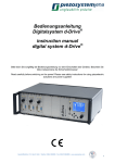
Instruction manual NV40/3 CLE NV40/3 piezosystem jena GmbH Prüssingstrasse 27 • 07745 Jena Tel. ++49 3641 6688-0 • Fax ++49 3641 6688-66 email: [email protected] • http://www.piezojena.de piezosystem jena GmbH is certified after DIN EN ISO 9001 since 1999. TRITOR®, nanoX® and d-Drive® are registered trade marks of piezosystem jena. Date: 07-02-15 Reviser: Dirk Wüstenhagen 2 piezosystem jena GmbH Prüssingstrasse 27 • 07745 Jena Tel. ++49 3641 6688-0 • Fax ++49 3641 6688-66 • email: [email protected] • http://www.piezojena.de This instruction manual includes important information for using piezo actuators. Please take time and read this information. Piezo positioning systems are mechanical systems with highest precision. Correct handling guarantees the precision over long time. Your actuator: Serial number: Your system: NV40/3 NV40/3 CLE Serial number: piezosystem jena GmbH Prüssingstrasse 27 • 07745 Jena Tel. ++49 3641 6688-0 • Fax ++49 3641 6688-66 • email: [email protected] • http://www.piezojena.de 3 Table of Contents 1. General instructions.................................................................................. 7 1.1. Safety instructions..................................................................................................... 7 1.2. General hints............................................................................................................. 8 1.3. Instructions for checking the function of the system / quick start.............................. 9 2. NV40/3CLE................................................................................................ 11 2.1. Key words............................................................................................................... 11 2.2. Introduction............................................................................................................. 12 NV 40/3CLE amplifier with integrated feedback controller system........................ 12 2.3. Initiation................................................................................................................... 13 2.4. User elements / connection..................................................................................... 13 2.4.1. Front panel....................................................................................................... 13 2.4.2. Back panel....................................................................................................... 13 2.5. Handling.................................................................................................................. 13 2.5.1. Main supply voltage......................................................................................... 13 2.5.2. Connecting piezo actuator............................................................................... 14 2.5.3. Graphic display................................................................................................ 14 2.5.4. Manual Control................................................................................................. 15 2.5.5. Controlling via modulation / monitor................................................................. 15 Monitor NV40/3CLE ............................................................................................. 15 Monitor NV40/3..................................................................................................... 15 2.5.6. Controlling via interface.................................................................................... 15 Configuration RS232............................................................................................. 16 Command list........................................................................................................ 16 Command 'setk'..................................................................................................... 16 Command 'set'....................................................................................................... 17 Command 'cloop'................................................................................................... 17 Command 'setall'................................................................................................... 17 Command 'rk'........................................................................................................ 17 Command 'measure'.............................................................................................. 17 Command 'ver'...................................................................................................... 18 Kommando 'fready'................................................................................................ 18 Kommando 'fenable'.............................................................................................. 18 Command 'ERR?'.................................................................................................. 18 Example................................................................................................................ 18 2.6. Technical data......................................................................................................... 20 2.7. Drawings................................................................................................................. 23 Output connector for actuator D-SUB15 ............................................................... 23 Modulation / Monitor D-SUB25............................................................................. 24 RS232 D-SUB9.................................................................................................... 25 USB 1.1................................................................................................................. 25 MAIN SUPPPLY VOLTAGE.................................................................................. 25 piezosystem jena GmbH Prüssingstrasse 27 • 07745 Jena Tel. ++49 3641 6688-0 • Fax ++49 3641 6688-66 • email: [email protected] • http://www.piezojena.de 5 1. General instructions 1.1. Safety instructions ● Never open the controller case. There are no user serviceable components inside. Electrical components inside cause a dangerous electrical hazard situation even when the amplifier is switched off. ● Please make sure that warm air generated by the amplifier modules will circulate out of case. Do not use the controller box near heating sources. ● Do not use near fluids which can enter case. aFluids can cause damages and short circuit the controller. ● If you want to disconnect the piezo electrical actuator, please turn the knob for “DClevel” counter clockwise to the starting point. Before you disconnect the piezo actuator, please switch off the controller case. ● Do not put any heavy parts on the top of the case, cable and any other part related to the piezo electrical actuator. ● The devices from piezosystem jena should be used in try and clean environment only. Only elements with a special preparation can be used under other conditions. ● Our warranty is only valid when using parts or accessories supplied by piezosystem jena. Piezosystem jena cannot be responsible for any damage caused by using other components. Please note, changing the cable and connector configuration can cause a malfunction of the system. ● Piezoelectrical actuating systems are high technology precision devices. Please use and handle such a system very carefully. Please touch and mount the systems only after being given user instruction. ● Please disconnect the controller case immediately if you see any of the following: ○ Damaged cables ○ Fluids entered in the system ○ If the systems is wet or has been in contact with a fluid ○ If the system does not work properly piezosystem jena GmbH Prüssingstrasse 27 • 07745 Jena Tel. ++49 3641 6688-0 • Fax ++49 3641 6688-66 • email: [email protected] • http://www.piezojena.de 7 1.2. General hints ● Piezoelectric actuators from piezosystem jena are controlled by voltages up to 150V. These values can be quite hazardous. Therefore read the installation instructions carefully and only authorized personal should handle the power supply. ● After transportation, piezoelectric systems should be allowed to adapt for approximately 2 hours to the room temperature before being switched on. ● Piezoelectric actuators are made from ceramic materials with and without metallic casings. The piezo-ceramic is a relatively brittle material. This should be noted when handling piezoelectrical actuators. All piezo-elements are sensitive to bending or shock forces. ● Due to the piezoelectric effect piezo-actuators can generate electrical charges by changing the mechanical load or the temperature or such actions described above. ● Piezoelectric actuators are able to work under high compressive forces, only actuators with pre-load can be used under tensile loads (these tensile forces must be less then the pre-load, given in the data sheet). ● Please note that the acceleration of the ceramic material (e.g., caused by mechanical shock, discharging or high dynamic application) may cause a damage. ● After excitation of the actuators by a voltage in the upper control range, the ceramic will move and generate an opposite high voltage after disconnection. ● Heating of the ceramic material will occur during dynamic operation. This may cause failure if the temperature exceeds specified values cited below. ● Increasing temperature up to the Curie temperature (usual values approx. 140°C 250°C) the piezoelectric effect disappears. ● Piezoelectric actuators such stacks or various tables work electrically as a capacitance. These elements are able to store electrical energy over a long period (up to some days) and the stored energy may be dangerous. ● If the actuator remains connected to the drive electronics it will be unloaded within a second after shut down and quickly reaches harmless voltage values. ● Piezo-actuators can generate voltages by warming or cooling only (caused by the longitudinal change). The discharge potential should not be ignored due to the inner capacitance. This effect is insignificant at usual room temperature. ● Piezo-actuators from piezosystem jena are adjusted and glued. Any opening of the unit will cause misalignment or possible malfunction and the guarantee will be lost. ● Please contact piezosystem jena or your local representative, if there are any problems with your actuator or power supply. Caution! Shock forces may damage the built-in ceramic element. Please avoid such forces, and handle the units with care, otherwise the warranty will be voided. 8 piezosystem jena GmbH Prüssingstrasse 27 • 07745 Jena Tel. ++49 3641 6688-0 • Fax ++49 3641 6688-66 • email: [email protected] • http://www.piezojena.de 1.3. Instructions for checking the function of the system / quick start When you open the package, please check to make sure all the necessary parts are included (see packing list) and nothing is damaged. Check the electronics and the actuator for any visible damage: ● The top and bottom plate of the actuator (if it does not have another shape) should be parallel to each other, without scratches. ● If there is any damage to the system please contact our local representative immediately! ● If the packaging material is damaged please notify the shipping company. Before you switch on the system, please check: ● The main voltage supplied in your country is the same as installed for the system. (Check the voltage label on the backside of the electronics!) ● The secondary voltage (DC) matches with the amplifier. If the system is damaged, please inform piezosystem jena. After switching on the NV40/3CLE the system executes a softstart function. This means the system increases the voltage slowly from -20 V to 130V and decrease slowly from 130 V to -20 V. piezosystem jena GmbH Prüssingstrasse 27 • 07745 Jena Tel. ++49 3641 6688-0 • Fax ++49 3641 6688-66 • email: [email protected] • http://www.piezojena.de 9 2. NV40/3CLE The NV40/3 and the NV40/3CLE are very similiar. In case of information which do refer to the NV40/3CLE this symbol will appoint it. -> not available in NV40/3 2.1. Key words NV40/3 piezo amplifier for up to 3 PZT actuators; RS232/USB interface; for piezo actuating systems without feed back sensor inside NV40/3CLE piezo amplifier for up to 3 PZT actuators; RS232/USB interface; for piezo actuating systems with feed back sensors inside (strain gauge or capacitive) GRAPHIC DISPLAY QVGA full color, 320x240 Pixel; constantly shows all values and status information POTENTIOMETER KNOB For manual voltage offset adjustment and for switching on and off CLOSED LOOP mode (NV40/3CLE only) CLOSED LOOP Operating mode for piezo actuating systems with integrated feed back sensor system. Position accuracy is constantly controlled OPEN LOOP Operating mode for actuating systems without feedback sensor inside; no position information available PC INTERFACE Serial RS232 interface or USB with 16bit resolution MODULATION INPUT The amplifier can be controlled by an external analogue voltage signal from 0V…10V MONITOR OUTPUT Output voltage signal which corresponds with the position of the piezo actuating system (CLOSED LOOP mode) or with the applied voltage signal (OPEN LOOP mode) AUTOMATICAL SENSOR IDENTIFICATION (ASI) NV40/3CLE amplifier can be used with strain gauge feed back sensors as well as with capacitive feed back sensors. The ASI function makes it possible to show the name of the actuator and the measurement system. MAIN SUPPLY VOLTAGE The main supply voltage to the amplifier is 24VDC; an external wide range power converter for 115V AC and 230V AC is included in the shipment REMOTE CONTROL piezosystem jena GmbH Prüssingstrasse 27 • 07745 Jena Tel. ++49 3641 6688-0 • Fax ++49 3641 6688-66 • email: [email protected] • http://www.piezojena.de 11 The remote control switches all manual controls (POTENTIOMETER KNOB and MODULATION) off or on. Please pay attention only if the remote control is switched on (1) it will be possible to use the „set“ command. HYPER TERMINAL PROGRAM Enables to control the piezoactuating system by using the RS232 interface. All necessary commands are given in the user manual 2.2. Introduction The amplifier module NV 40/3 and NV 40/3CLE are designed for parallel control of up to three low voltage piezo actuators with and without internal feed back sensor system. The amplifier comes as a stand alone device with standard PC INTERFACE RS232 and USB. A GRAPHIC DISPLAY constantly shows all status information such as voltage and motion. Each piezo can be controlled separately either by turning the voltage offset, by applying an analog voltage signal of 0..10V or by PC interface. The voltage of the MOINITOR OUTPUT correspondents to either applied piezo voltage (NV40/3) or completed motion (NV40/3CLE). The NV 40/3 is designed for controlling only OPEN LOOP actuating systems without any feed back sensor inside. The NV 40/3CLE is designed for piezo actuating system with strain gauge or capacitive feed back sensors inside. In this case, the sensor signal is prepared by an external pre-amplifier inside the cable. The AUTOMATICAL SENSOR IDENTIFICATION “ASI” enables the customer to use the amplifier unit NV 40/3CLE with different piezo actuators of the same product series. This enables the controller unit to read all system information from the actuating systems which are stored inside the connector and transmit this information to the amplifier unit. NV 40/3CLE amplifier with integrated feedback controller system Analog actuating systems with integrated feedback sensors are calibrated with a particular amplifier unit. Only systems consisting of piezo and amplifier which are calibrated to each other can be used together to reach the full accuracy performance. Exchanging of actuating system is possible in this case only if the actuating system is from the same product group. Otherwise the CLOSED LOOP controller can be damaged! Example: If the amplifier NV 40/3CLE is calibrated for MIPOS 100 SG series (range of motion 100µm), then it can be used with different MIPOS 100 SG actuators, but not with MIPOS 250 SG (range of motion 250µm) or a MIPOS 100 CAP(different measurement system). If an actuator is connected to a channel of the amplifier NV40/3CLE which it was not calibrated with, it won't be possible using in closed loop. Please note that the information about the operation mode (closed loop, open loop) are automatically stored if the system is switched off. When it is switched on again, the last operation mode is set again. The system starts automatically at the minimal position after it is switched on. NV40/3 without feed back controller Please note that by switching on the amplifier the voltage signal is applied direct to the connected piezo actuating system. A shock voltage signal applied to the piezo actuating system can affect system's life time. 12 piezosystem jena GmbH Prüssingstrasse 27 • 07745 Jena Tel. ++49 3641 6688-0 • Fax ++49 3641 6688-66 • email: [email protected] • http://www.piezojena.de 2.3. Initiation Please follow all safety instruction given in chapter 1 before using the amplifier. 2.4. User elements / connection 2.4.1. Front panel Graphic display Potentiometer knob channel 1 Potentiometer knob channel 2 Potentiometer knob channel 3 2.4.2. Back panel Connector for modulation (MOD) and monitor (MON) RS232interface Switcher power ON/OFF Connector for actuators Main supply voltage piezosystem jena GmbH Prüssingstrasse 27 • 07745 Jena Tel. ++49 3641 6688-0 • Fax ++49 3641 6688-66 • email: [email protected] • http://www.piezojena.de USBinterface 13 2.5. Handling 2.5.1. Main supply voltage The amplifier NV 40/3 and NV 40/3CLE require a main supply voltage of 24VAC. A power supply unit suitable for voltage from 115V/50Hz up to 230V/50Hz AC is included in the shipment. The socket for the main supply voltage is located on the back panel of the amplifier. 2.5.2. Connecting piezo actuator The piezo actuating systems is connected to the amplifier unit by using the D-SUB CONNECTOR on the back panel. Please make sure that the amplifier is switched off by connecting the PZT with the amplifier. Please fasten the screws of the D-SUB CONNECTOR and guarantee a firm connection. If the display shows the information “NOT CONNECTED” then please check the connection between PZT connector and amplifier again. 2.5.3. Graphic display The GRAPHIC DISPLAY shows the following status information: Name of axis of actuator Operating mode „open loop“ Piezo voltage Remote modus activated „REMOTE“ Operating mode „closed loop“ only NV40/3CLE Graphic 1: Display NV40/3CLE Controlling via RS232 active No actuator connected Actuator position* Actuator out of closed loop range* Internal temperature Graphic 2: Display NV40/3CLE warning * not available on NV40/3 14 piezosystem jena GmbH Prüssingstrasse 27 • 07745 Jena Tel. ++49 3641 6688-0 • Fax ++49 3641 6688-66 • email: [email protected] • http://www.piezojena.de 2.5.4. Manual Control Each channel of the amplifier can be controlled by turning the POTENTIOMETER KNOB on the front panel. Turning clockwise increases the applied voltage signal, turning counterclockwise reduces the applied voltage signal. The CLOSED LOOP mode of the NV 40/3CLE amplifier can be switched on and off by pressing the potentiometer knob for each channel. If you switch off the amplifier the operational mode (closed loop, open loop) will be saved, and after switching on, the amplifier starts again with its last operational mode. 2.5.5. Controlling via modulation / monitor The amplifier can be controlled by an external MODULATION signal from 0…10V. An adapter cable with BNC to D-SUB connector is included. The MODULATION is marked on the back panel by MOD. By using an external MODULATION signal in OPEN LOOP mode 0V correspond to a value of –20V and 10V correspond to voltages signal of 130V applied to the piezo actuating system. In CLOSED LOOP mode 0V corresponds to the a motion of 0µm, 10V correspond to the max. motion based on the specification of the used piezo actuating system. EXAMPLE: MIPOS 100 SG PL (part. no. O-323-01E) Position minimal maximal OPEN LOOP: 0V= -20V 10V= 130V CLOSED LOOP: 0V=0µm 10V= 100µm The actuating system will move (up to 20% of full motion) when switching on and off the CLOSED LOOP mode () because of different voltage signals. Monitor NV40/3CLE The MONITOR output provides a voltage signal which correspondents directly to the position of the piezo actuating system. The value for the MONITOR output voltage range is from –5V to +5V in CLOSED LOOP mode and form –8V to 8V in OPEN LOOP mode (minimum and maximum of motion range). The difference in both signal's values is caused by the CLOSED LOOP control reserve. Monitor NV40/3 The MONITOR output of the NV 40/3 always provides a signal of 0V up to 10V which directly corresponds to the voltage signal applied to the piezo actuator. Based on this a signal of 0V is related to an applied voltage of –20V and 10V is related to 130V. piezosystem jena GmbH Prüssingstrasse 27 • 07745 Jena Tel. ++49 3641 6688-0 • Fax ++49 3641 6688-66 • email: [email protected] • http://www.piezojena.de 15 2.5.6. Controlling via interface For external control via PC, a USB or RS232 interface can be used. Make sure that the amplifier is switched off before connecting with the PC. The interface on the back plane is marked with RS232. A HYPER TERMINAL PROGRAM can be used for control via serial interface RS232. In order to use the USB interface, please install the driver software first. All commands are given in following chapter. Configuration RS232 For external control by PC interface RS232 the following settings are necessary Baud rate / Bits per second: 19200 Data bits: 8 Stop bits: 1 Parity : none Flow control: Software (XON / XOFF) For external control via RS232, you may use the HYPER TERMINAL PROGRAM of your PC. Command list Command Statement setk switch the remote control for one channel on or off cloop switch one channel to closed loop or open loop set set the values to one channel setall set the values to all channels rk measures the value either of position (only NV40/3CLE) or voltage (only NV40/3) only for one channel measure measures values of all channels either for position () or voltage ver gives the version number of controller and amplifier software ERR? shows the last error Table 1: Command list The numbers for the channels starts with „0“. Connector “PIEZO 1” equals channel number “0”. All commands which included a value have to be separated by dots. Example: The value 22,5 µm must be programmed by the command <22.5> Command 'setk' Call: setk,<ch>,<0|1> Exsample: setk,0,1 Answer: none Set the actuator on channel 1 to remote control. The command setk switches the remote control for one channel <ch> on <1> or off <0>. If the remote control is activated you won't be able to change the position either by the POTENTIOMETER KNOB or via MODULATION. Turning the remote control off, the position of the actuator goes to minimal position. 16 piezosystem jena GmbH Prüssingstrasse 27 • 07745 Jena Tel. ++49 3641 6688-0 • Fax ++49 3641 6688-66 • email: [email protected] • http://www.piezojena.de Command 'set' Call: set,<ch>,<value> Example: set,0,5.53 Answer: none Set the position of the actuator to the given value. In CLOSED LOOP (only NV40/3CLE) the value is 5,53 µm. In OPEN LOOP the value means 5,53 V. The command “set” sets a channel <ch> to the given value <value>. In CLOSED LOOP () the value means µm. In OPEN LOOP the value means the voltage which is applied to the actuator. Please pay attention that the REMOTE CONTROL has been switched on before. Command 'cloop' Call: cloop,<ch>,<0|1> Example: cloop,1,0 Answer: none Channel 2 (PIEZO 2) is set to the operation modus open loop. The command “cloop” switches channel of the amplifier () to the operation mode CLOSED LOOP <1> or to OPEN LOOP <0>. Command 'setall' Call: setall,<value0>,<value1>,<value2> Example: setall,22,1.5,-5.53 Answer: none Sets the position of the actuator to the given value <value0..2>. For instance PIEZO1 to 22 and PIEZO 2 to 1,5 and PIEZO 3 to -5,53 (only possible if the operation mode OPEN LOOP) . The command “setall” sets all channels to the given values <value>. In CLOSED LOOP () the value <value0..2> means µm. In OPEN LOOP the value <value0..2> means the voltage which is applied to the actuator. Please take care that the REMOTE CONTROL for all channels has to be switched on. Command 'rk' Call: rk,<ch> Example: rk,1 Answer: rk,<ch>,<value> rk,1,20.016 The command „rk“ reads out either the position <value> for one channel <ch> from the measurement system () or the voltage applied to the piezo. The readout value <value> is given with 3 decimal places. Command 'measure' Call: measure Example: measure Answer: aw,<value0>,<value1>,<value2> aw,0.015,5.003,150.002 The command „measure“ reads out either the position <value0..2> from the measurement system () or the voltage applied to the actuator. The read out values <value0..2> are given with 3 decimal places. piezosystem jena GmbH Prüssingstrasse 27 • 07745 Jena Tel. ++49 3641 6688-0 • Fax ++49 3641 6688-66 • email: [email protected] • http://www.piezojena.de 17 Command 'ver' Call: ver Example: ver Answer: version,vnumber,vdate ver,1.000.799 sdate,11/09/2006 serno,23579 This Command “ver” reads out the software version number of the internal controller, the date and the serial number of the amplifier. Command 'fready' Call: fready,<0|1> Example: fready,1 Answer: none The soft start is switched on for all channels This command 'fready' enables the soft start function for all channels. After switching on the system the soft start function is started for 10seconds to initiate the actuator. While this routine the actuator is moved once through the whole motion range and back. While softstart the modulation input and the offset potentiometer are disabled. After the softstart the amplifier is working normally. If no parameter set after the command 'fready' the controller gives the status of softstart function for all channels. Command 'fenable' Call: fenable,<ch>,<0|1> Example: fenable,0,1 Answer: none The soft start function is switched on for the channel 0 (PIEZO 1). This command 'fenable' enables the soft start function for the given channel. After switching on the system the soft start function is started for 10seconds to initiate the actuator. While this routine the actuator is moved once through the whole motion range and back. While softstart the modulation input and the offset potentiometer are disabled. After the softstart the amplifier is working normally. If only the parameter for the channel set after the command 'fenable' the controller gives back the status of softstart function for the channel. Command 'ERR?' Call: ERR? Example: ERR? Answer: ERROR,<“last error“> ERROR,"OK. No error." The command “ERR?” gives the last failure from the controller. After read out the error from the controller the failure status in the memory will be deleted. The output of the error message occurs as plain text. 18 piezosystem jena GmbH Prüssingstrasse 27 • 07745 Jena Tel. ++49 3641 6688-0 • Fax ++49 3641 6688-66 • email: [email protected] • http://www.piezojena.de Example This example shows the sequence of the commands to move the actuator with the NV40/3CLE from the minimal position 0 µm to 10µm. Command Answer Explanation [Enter] NV403CL> setk,0,1 none Activates the REMOTE CONTROL on channel 1 cloop,0,1 none Switches channel 1 to operation mode CLOSED LOOP set,0,10 none Set channel 1 to 10µm rk,0 rk,0,10.000 After press the [Enter] key on the computer keyboard the prompt shows “NV403CL>” in the HYPER TERMINAL PROGRAM. Piezo connected to channel 1 stands at the position 10µm table 2: Example for REMOTE CONTROL NV40/3CLE piezosystem jena GmbH Prüssingstrasse 27 • 07745 Jena Tel. ++49 3641 6688-0 • Fax ++49 3641 6688-66 • email: [email protected] • http://www.piezojena.de 19 2.6. Technical data Number of channels Max. output power Output voltage Output current Output voltage stability Noise of output voltage Modulation input (MOD) Inner resistance DC offset Display Output connector (PIEZO1..3) Monitor voltage (MON) NV40/3CLE Monitor voltage (MON) NV40/3 Closed loop control () Dimensions w x h x l Interface Features Main power supply 20 3 3 x 5,2W -20V ... +130V 3x 40mA typ.<1mV <0,3mVRMS @ 500 Hz 0V ... +10V, D-SUB25pin 10 kΩ 3 x Potentiometer knob QVGA full color, 320x240 pixel 3 x D-SUB15pin. -8V ... +8V, D-SUB25pin, output resistance <100Ω (operation mode OPEN LOOP) -5V ... +5V, D-SUB25pin, output resistance <100Ω (operation mode Closed LOOP) 0V ... +10V, D-SUB25pin, output resistance <100Ω PID analogue, switched by pushing on potentiometer knob 210mm x 88mm x 240mm RS232 D-SUB9pin. Softstart function ASI – function overvoltage protection overheating protection Short-circuit-proof Closed loop control () optional: System optimisation dependant on weight 24VDC/2,5A (wide range main power supply 90-264VAC) table 3: technical data NV40/3CLE piezosystem jena GmbH Prüssingstrasse 27 • 07745 Jena Tel. ++49 3641 6688-0 • Fax ++49 3641 6688-66 • email: [email protected] • http://www.piezojena.de 2.7. Drawings Output connector for actuator D-SUB15 Pin Explanation 8 Voltage for actuator 15 Ground for actuator 7 n.c. 14 Ground 6 +5V 13 „Detect“ to identify actuator 5 SDA for ID-Chip 12 SCL for ID-Chip 4 Ground 11 Analogue ground 3 +15V 10 -15V 2 Analogue ground 9 measuring input 1 measuring input table 4: Actuator connector NV40/3CLE piezosystem jena GmbH Prüssingstrasse 27 • 07745 Jena Tel. ++49 3641 6688-0 • Fax ++49 3641 6688-66 • email: [email protected] • http://www.piezojena.de 21 Modulation / Monitor D-SUB25 Pin Explanation 1 Modulation channel1 14 Ground 2 Monitor channel1 15 Ground 3 MOD-MON difference channel1 16 Ground 4 n.c. 17 n.c. 5 Modulation channel2 18 Ground 6 Monitor channel2 19 Ground 7 MOD-MON difference channel2 20 Ground 8 n.c. 21 n.c. 9 Modulation channel3 22 Ground 10 Monitor channel3 23 Ground 11 MOD-MON difference channel3 24 Ground 12 n.c. 25 n.c. 13 n.c. Table 5: Modulation/Monitor connector NV40/CLE 22 piezosystem jena GmbH Prüssingstrasse 27 • 07745 Jena Tel. ++49 3641 6688-0 • Fax ++49 3641 6688-66 • email: [email protected] • http://www.piezojena.de RS232 D-SUB9 Pin Description Explanation 2 TxD RS232 transmitter 3 RxD RS232 receiver 5 GND RS232 Ground 4,6 Bridge 7,8 Bridge Table 6: RS232-connector NV40/3CLE USB 1.1 Pin Description Explanation 1 VCC 2 D- Data - 3 D+ Data + 4 GND Supply voltage +5V Main power supply ground Table 7: USB-connector NV40/3CLE MAIN SUPPPLY VOLTAGE The NV40/3CLE and NV40/3 need 24V DC and require at least a current of 2,5A. The 2,1 mm barrel connector in the NV40/3 and NV40/3CLE has the following layout. +24V Ground piezosystem jena GmbH Prüssingstrasse 27 • 07745 Jena Tel. ++49 3641 6688-0 • Fax ++49 3641 6688-66 • email: [email protected] • http://www.piezojena.de 23