1
U NIVERSITATEA P OLITEHNICA DIN T IMIŞOARA
F ACULTATEA DE A UTOMATIC Ă ŞI C ALCULATOARE
D EPAR TAMENTUL C ALCULATOARE
D EFINING AND C HECKING C OMPLEX
A RCHITECTURAL R ULES IN E CLIPSE
G EORGE G ANEA
C ONDUC ĂTOR Ş TIINŢIFIC :
C ONF. DR . ING . R ADU M ARINESCU
Contents
1 Introduction
1.1 Context . . . . . . . .
1.2 The Problem . . . . .
1.3 Contribution . . . . .
1.4 Diploma Organization
.
.
.
.
.
.
.
.
.
.
.
.
.
.
.
.
.
.
.
.
.
.
.
.
.
.
.
.
.
.
.
.
2 Theoretical Foundations
2.1 Object Oriented Design . . . . . . .
2.2 Code Abnormalities . . . . . . . . .
2.3 Design Abnormalities . . . . . . . .
2.4 Architecture Abnormalities . . . . .
2.5 Detection of Design Abnormalities
.
.
.
.
.
.
.
.
.
.
.
.
.
.
.
.
.
.
.
.
.
.
.
.
.
.
.
.
.
.
.
.
.
.
.
.
.
.
.
.
.
.
.
.
.
.
.
.
.
.
.
.
.
.
.
.
.
.
.
.
.
.
.
.
.
.
.
.
.
.
.
.
.
.
.
.
.
.
.
.
.
.
.
.
.
.
.
.
4
5
6
6
7
.
.
.
.
.
.
.
.
.
.
.
.
.
.
.
.
.
.
.
.
.
.
.
.
.
.
.
.
.
.
.
.
.
.
.
.
.
.
.
.
.
.
.
.
.
.
.
.
.
.
.
.
.
.
.
.
.
.
.
.
.
.
.
.
.
.
.
.
.
.
.
.
.
.
.
.
.
.
.
.
.
.
.
.
.
.
.
.
.
.
.
.
.
.
.
.
.
.
.
.
8
8
11
12
13
14
3 State Of The Art
3.1 Quality Assurance Tools . . . . . . . . .
3.1.1 ADLs . . . . . . . . . . . . . . . . .
3.1.2 Lattix LDM . . . . . . . . . . . . .
3.1.3 Moose . . . . . . . . . . . . . . . .
3.1.4 iPlasma . . . . . . . . . . . . . . .
3.2 Eclipse as a code analysis platform . . .
3.2.1 Plugin Development Environment
3.2.2 Eclipse Modeling Framework . .
3.2.3 Java Development Tools . . . . .
3.2.4 Xtext . . . . . . . . . . . . . . . .
3.2.5 inCode . . . . . . . . . . . . . . .
.
.
.
.
.
.
.
.
.
.
.
.
.
.
.
.
.
.
.
.
.
.
.
.
.
.
.
.
.
.
.
.
.
.
.
.
.
.
.
.
.
.
.
.
.
.
.
.
.
.
.
.
.
.
.
.
.
.
.
.
.
.
.
.
.
.
.
.
.
.
.
.
.
.
.
.
.
.
.
.
.
.
.
.
.
.
.
.
.
.
.
.
.
.
.
.
.
.
.
.
.
.
.
.
.
.
.
.
.
.
.
.
.
.
.
.
.
.
.
.
.
.
.
.
.
.
.
.
.
.
.
.
.
.
.
.
.
.
.
.
.
.
.
.
.
.
.
.
.
.
.
.
.
.
.
.
.
.
.
.
.
.
.
.
.
.
.
.
.
.
.
.
.
.
.
.
.
.
.
.
.
.
.
.
.
.
.
.
.
.
.
.
.
.
.
.
.
.
.
.
.
.
.
.
.
.
.
.
.
16
16
16
17
18
18
19
20
20
21
22
22
. . . .
Rules
. . . .
. . . .
. . . .
. . . .
. . . .
. . . .
. . . .
. . . .
. . . .
. . . .
. . . .
. . . .
.
.
.
.
.
.
.
.
.
.
.
.
.
.
.
.
.
.
.
.
.
.
.
.
.
.
.
.
.
.
.
.
.
.
.
.
.
.
.
.
.
.
.
.
.
.
.
.
.
.
.
.
.
.
.
.
.
.
.
.
.
.
.
.
.
.
.
.
.
.
.
.
.
.
.
.
.
.
.
.
.
.
.
.
.
.
.
.
.
.
.
.
.
.
.
.
.
.
.
.
.
.
.
.
.
.
.
.
.
.
.
.
.
.
.
.
.
.
.
.
.
.
.
.
.
.
.
.
.
.
.
.
.
.
.
.
.
.
.
.
.
.
.
.
.
.
.
.
.
.
.
.
.
.
.
.
.
.
.
.
.
.
.
.
.
.
.
.
24
24
24
25
27
28
31
31
32
34
35
38
38
38
39
.
.
.
.
.
.
.
.
.
.
4 A Language for Expressing the Design
4.1 Motivation . . . . . . . . . . . . . . . . . . . . .
4.2 Language Anatomy / Categories of Supported
4.2.1 Use rule . . . . . . . . . . . . . . . . . .
4.2.2 Have Rule . . . . . . . . . . . . . . . . .
4.2.3 Exception Mechanism . . . . . . . . . .
4.3 Rules by Granularity . . . . . . . . . . . . . .
4.3.1 Architectural level rules . . . . . . . . .
4.3.2 Design level rules . . . . . . . . . . . .
4.3.3 Code level rules . . . . . . . . . . . . . .
4.4 Grammar . . . . . . . . . . . . . . . . . . . . .
4.5 Rules Editor . . . . . . . . . . . . . . . . . . .
4.5.1 Auto-complete - generated . . . . . . .
4.5.2 Smart auto-complete . . . . . . . . . .
4.5.3 Code coloring . . . . . . . . . . . . . . .
2
CONTENTS
3
4.5.4 Editor Outline View . . . . . . . . . . . . . . . . . . . . . . . . . . .
4.6 User Interface . . . . . . . . . . . . . . . . . . . . . . . . . . . . . . . . . .
5 Execution Mechanics
5.1 Xtext Grammar . . . . . . . . . . . . .
5.1.1 Xtext grammar features used
5.1.2 Grammar definition . . . . . .
5.2 Generated Entities . . . . . . . . . . .
5.2.1 AST . . . . . . . . . . . . . . . .
5.2.2 The Parsing process . . . . . .
5.2.3 EMF model . . . . . . . . . . .
5.2.4 Proposal Engine . . . . . . . .
5.3 Rule Evaluation . . . . . . . . . . . .
5.3.1 inCode metamodel . . . . . . .
5.3.2 Group building . . . . . . . . .
5.3.3 Implemented Visitors . . . . .
.
.
.
.
.
.
.
.
.
.
.
.
.
.
.
.
.
.
.
.
.
.
.
.
.
.
.
.
.
.
.
.
.
.
.
.
.
.
.
.
.
.
.
.
.
.
.
.
.
.
.
.
.
.
.
.
.
.
.
.
.
.
.
.
.
.
.
.
.
.
.
.
.
.
.
.
.
.
.
.
.
.
.
.
.
.
.
.
.
.
.
.
.
.
.
.
.
.
.
.
.
.
.
.
.
.
.
.
.
.
.
.
.
.
.
.
.
.
.
.
.
.
.
.
.
.
.
.
.
.
.
.
.
.
.
.
.
.
.
.
.
.
.
.
.
.
.
.
.
.
.
.
.
.
.
.
.
.
.
.
.
.
.
.
.
.
.
.
.
.
.
.
.
.
.
.
.
.
.
.
.
.
.
.
.
.
.
.
.
.
.
.
.
.
.
.
.
.
.
.
.
.
.
.
.
.
.
.
.
.
.
.
.
.
.
.
.
.
.
.
.
.
.
.
.
.
.
.
.
.
.
.
.
.
.
.
.
.
.
.
.
.
.
.
.
.
.
.
.
.
.
.
40
41
43
44
44
44
47
47
48
49
49
51
51
54
56
6 Conclusions
59
A Entity Properties Definitions
A.1 Class Filters . . . . . . . . . . . . . . . . . . . . . . . . . . . . . . . . . . .
A.2 Method Filters . . . . . . . . . . . . . . . . . . . . . . . . . . . . . . . . . .
61
61
61
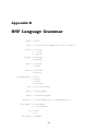
B BNF Language Grammar
62
C Xtext Grammar
64
Bibliography
68
Chapter 1
Introduction
In the last couple of decades the size and complexity of software systems has been
growing exponentially. Nowadays, the generally adopted software development technique is Object Oriented Programming. The Object Oriented approach promises to
provide a method to manage the complexity of the software system in a far better way
than the previous general accepted programming paradigm - procedural programming.
However, the Object Oriented approach to developing software systems is not so easy
to learn and very hard to master. This is why, even if the system was developed using
Object Oriented Programming it does not guarantee the fact that the it will be able to
evolve in order to maintain its business value and satisfy its clients [Rat03].
The issue of maintainability of the system gained an important place in the software
development process. Most of the causes of the maintainability problems are directly
related to the poor design of the software system.
Maintainability is not just about repair work, or (a more popular, more informal expression) fixing bugs. Maintainability is also about further development of the system,
adding new behavior, new features, adapting the system in order to work in a different
environment (e.g. a different operating system).
Another issue is that of the documentation, because it is not being updated once
new features are added, or a bug is fixed, it makes the new enhancements very difficult to be added without breaking the current architecture. ”Documenting software
architecture facilitates communication between stakeholders, documents early decisions about high-level design, and allows reuse of design components and patterns
between projects”[BCK98].
The documentation of every project contains at least a few schemas in the Unified
Modeling Language (UML).
”The Unified Modeling Language (UML) is a family of graphical notations, backed by
single meta-model, that help in describing and designing software systems, particularly software systems built using the object-oriented (00) style. That’s a somewhat
simplified definition. In fact, the UML is a few different things to different people. This
comes both from its own history and from the different views that people have about
what makes an effective software engineering process.”[Fow97]
The UML is a very powerful tool for expressing, communicating and documenting design decisions. But, because most of the documents written in UML are written by
4
1.1. CONTEXT
5
hand, on paper, few of them are drawn with a graphics applications, fewer are drawn
with the aid of a UML tool and not all of the UML tools can actually ”keep-up” with the
code development, a documentation solution that can ”keep-up” with the code (while
being understood by most people, like the UML) is needed.
1.1
Context
As the diploma [Tri03] clearly states: ”adding new functionality to an existing software is a very delicate procedure. It takes a lot of expertise and careful revision of the
architecture each time a new piece of functionality, that was not anticipated before,
is added” the architecture is central to the software development process. ”However,
anticipating future enhancements and providing hooks for their seamless integration without signicant overhead may sometimes be impossible either because of time
constraints or simply because some enhancements cannot be foreseen. As a result,
software begins to ’age’ [Par01], its architecture begins to degrade as it is littered with
new functionality”[Tri03].
The system architecture is, aside the user manual, them most important part of the
documentation of a software system. It describes all the major components of a software system and their interactions. It is ”the overall structure of the software and
the ways in which that structure provides conceptual integrity for a system” [SG96],
[GS94].
”A software architecture is the development work that gives the highest return on investment with respect to quality, schedule and cost”[BCK98]. This means that a good
architecture, can by itself, improve by a very large margin the success of the entire
project because many of the activities executed during later stages of development
depend on it.
The quality of the final product, especially its modularity and its reusability all depend on the programmers ability to understand, implement and maintain the initial
architecture of the system. Problems appear due to the evolution in parallel of the
architecture and of the source-code. The problem is known as architectural mismatch
[GAO95] : ”at the time the system architecture is published it is already obsolete”.
This problem is very important, especially in the industry [FRJar] where the engineers must work for up to 15 years [SSWA96] with the architecture [MW99].
Software Erosion, a concept described by Dalgarno et al. is a different but similar matter: ”At the architectural level, Software Erosion is seen in the divergence of
the software architecture as-implemented from the software architecture as-intended.
Note that when talking about the architecture as-intended Im not speaking here about
the initial planned architecture of the software system. Software architectures should
evolve over time this is to be expected as new requirements emerge so the intended
architecture is what your current conception of the architecture is. With software erosion what were talking about are unintended modifications or temporary violations of
the software architecture.” [Dal09]
If the development team is lacking a method to maintain a close connection between
the source-code and the architecture, then the project manager has to spend time
resources (development time turns to maintenance time) or even worse, request the
6
CHAPTER 1. INTRODUCTION
intervention of a third party.
The same point is made by Dalgarno el al.: ”The problem with software erosion is that
its effects accumulate over time to result in a significant decrease in the ability of a
system to meet its stakeholder requirements.”
”Unless you take steps to actively pinpoint and stop software erosion it will gradually
creep up on you and make changing the software further significantly harder and
less predictable. In the worst case it could lead to the cancellation of the project or,
for particularly significant projects, the closure of the business.”[Dal09] This is one
of the aims of this diploma project, to actively maintain a link between the intended
architecture and the source-code.
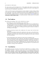
1.2
The Problem
The problem this diploma solves can be divided in tree parts:
• Readability and understandability of the architecture.
The readability and the understandability of the architecture is crucial to the development process in the sense that if the architecture is not understood well by
the stakeholders in general and by the developers in particular, then the whole
project has a very high chance of failing (not meeting the scheduled deadline or
not fitting in the budget).
• Lack of consistency between the architecture, the source-code and the documentation.
The lack of consistency between the architecture, the source-code and the documentation is a problem solved by few other tools. Most only solve the consistency
problems between the source-code and the architecture or the source-code and
the documentation.
• Lack of integration of the architecture tool and the development tool.
The lack of integration of the architecture tool with the development tool means
that even if the source-code is kept consistent with the architecture, this process
does not happen inside the development environment. This means that the architecture can no be changed automatically to be consistent with the code. The
developer must reiterate the architecture extraction process every time the code
mandates a change in the architecture.
1.3
Contribution
This diploma presents a new way to describe the architecture of a software system.
The proposed solution is made up, on one side, of the conceptual definition of the
inCode.Rules language, a domain specific language used for defining architectural
rules, and on the other, of the complete implementation of this language as an Eclipse
plugin and of an advanced editor. The implementation is based on the inCode software assurance platform and the language construction and editor is based on the
1.4. DIPLOMA ORGANIZATION
7
Xtext framework for textual development languages.
The key advantages of this solution are :
• Flexibility
The inCode.Rules language allows for designing complex architectural rules.
• Integration
Complete integration with the Eclipse development environment, with allows for
automated checking of the architectural integrity down to the source-code level
• The use of a fairly simple language, easy to understand and read, without any
mathematical notations, XML schemas or graphical representations.
1.4
Diploma Organization
The diploma is organized in six chapters, the first of which is the introduction, the
second chapter states the foundations of the work, the third chapter - the State Of The
Art provides and overview of the software environment the language was developed in
and some of the more interesting similar approaches to architecture description. The
fourth chapter describes the inCode.Rules architecture description language, the description is made from the users point of view. If one wishes to use the inCode.Rules
plugin then that’s the chapter to read. The fifth chapter describes the inner workings
of the plugin and how the rules are interpreted. The last chapter is the conclusions
chapter, it summarizes the work, the current limitations of the inCode.Rules plugin
and describes future work.
Chapter 2
Theoretical Foundations
This chapter presents the theoretical foundations that are at the core of the proposed
solution. First we cite and explain a suite of Object Oriented Design Principles meant
to maintain a high quality standard of the software system. Secondly we describe
a few design ”solutions” that recurrently appear in software projects, but which are
wrong and as a consequence lead to software decay[Par94].
2.1
Object Oriented Design
Object oriented design is a discipline in software engineering that deals with the organization of a system of objects that interact with each other in full conformity with
the rules of object oriented programming : inheritance,polymorphism, information hiding,abstraction. Next a number of seven selected design principles were selected and
described that are closest to this work. These principles were conceived by people
such as Barbara Liskov, Bertrand Meyer, Robert C. Martin and were compiled by
Robert C. Martin in a series of six articles.
Single Responsibility Principle Definition:
”There should never be more than one reason for a class to change.”[Mar00]
The responsibility of a class is defined as ”a reason to change”. Each responsibility
is another axis of change. If a given class has more than one axis of change, when
the requirements change, changing the class will inadvertently change the behavior
of the class in respect with other responsibilities.
This also means that the change will affect the modules that depend on the class and
that those will need to be changed even though they are in a completely different area
than the area with the changed requirements.
Of course, this leads to very fragile code, that is difficult to maintain because, if
changed, it can break in totally different and unexpected places.
The conclusion of Robert C. Martin is worth reading : ”The SRP is one of the simplest
of the principle, and one of the hardest to get right. Conjoining responsibilities is
something that we do naturally. Finding and separating those responsibilities from
one another is much of what software design is really about. Indeed, the rest of the
8
2.1. OBJECT ORIENTED DESIGN
9
principles we will discuss come back to this issue in one way or another.”
Classes that break this principle can be detected if they contain clusters of methods
and data : groups of methods that access different groups of attributes. One group
of methods accesses a group of data, while another one accesses a totally different
group of data.
Open Closed Principle Definition:
”Software entities (classes, modules functions, etc.) should be open for extension, but
closed for modification” [Mar96a]
The ”open for extension” part simply means that the behavior of a module in general
(a class in particular) can be extended so that the module behaves in a different way,
according to the changed requirements specification.
The ”closed for modification” part, is the tricky bit. At first it seems that it’s impossible
to change the behavior of a module without actually changing it. But, the principle
relies on the abstraction mechanism of Object Oriented Programming.
By using inheritance we can create several classes that have the same interface to
their clients but act differently. This means that we have closed the client for modification as we do not need to change the client any more to change the behavior, all we
need to do is add another class and the behavior of the client changes subsequently.
Liskov Substitution Principle Definition:
”Functions that se pointers or references to base classes must be able to use objects
of derived classes without knowing it.”[Mar96b]
This principle can be translated as : if we change the object a client (which is of
course another object) is using with an object that belongs to a derived class, then
the behavior of the client is not changed.
The key to this principle is the fact that the inheritance relation should be based on
the description of the behavior of the classes. A class A is a class B if the behavior of
class B can be replaced by that of class A with no problems. In the article [Mar96b],
the principle is explained with the square and rectangle classes and it is proven that
a square object is not a rectangle object.
Acyclic Dependencies Principle Definition:
”The dependency structure between packages must be a Directed Acyclic Graph (DAG).
That is, there must be no cycles in the dependency structure.”[Mar97a]
While this principle is very easy to understand, especially to java developers that
actually use the therm ”package” in the language, the implications of breaking this
principle is quite serious. If, for instance there are multiple teams, working on the
10
CHAPTER 2. THEORETICAL FOUNDATIONS
same project, each working on a different package (or subsystem) and only one wrong
dependency is made in the wrong way (thus introducing a cycle), the whole project
becomes one big package. This is because each package indirectly depends on all the
other packages. They all must be released at the same time.
Stable Dependencies Principle Definition:
”The dependencies between packages in a design should be in the direction of the stability of the packages. A package should only depend upon packages that are more
stable than it is.”[Mar97b]
The stability of a package can be translated as the resistance to change. The harder
it is to change a package, the more stable it is. The easier to change a package the
less stable (or more instable) it is.
The stability of a package can be determined using software metrics. The metrics
used to determine the stability of a package are based on the dependencies to and
from the package.
• Ca Afferent Couplings: The number of classes ouside this package that depend
upon classes within this package.
• Ce Efferent Couplings: The number of classes inside this package that depend
upon classes outside this package.
• I Instability : (Ce / (Ca+Ce)). Ranges from 0 to 1. 0 is maximally stable and 1 is
maximally instable.
Stable Abstractions Principle Definition:
”Packages that are maximally stable should be maximally abstract. Instable packages should be concrete. The abstraction of a package should be in proportion to its
stability.”[Mar97b]
This principle is related to the Open Closed Principle. It says the packages that
are depended upon should be abstract and those that depend on those packages
should be concrete. In other words if the classes in a package are very ”popular” then
they should be abstract. Because if they are abstract, then, when the requirements
change, and we need to change the behavior of the system, all we need to do is subclass the abstract classes. Subclassing means, of course, adding new code and not
changing the existing classes.
In the next three sections we will enumerate some of the design problems encountered
in software projects. We have categorized them according to the level of abstraction
that they occur.
2.2. CODE ABNORMALITIES
2.2
11
Code Abnormalities
”Bad smells” is a therm (referring to programming of course) Kent Beck first came up
with while writing a chapter with Martin Fowler in the ”Refactoring book” [FBB+ 99].
Bad smells provide a hint that something, somewhere went wrong in the source-code.
The bad smell can be used to track down the problem.
Duplicated code is not just a smell, it is a problem in itself. The problem with duplicated code is that if a bug needs to be fixed and the fix happens to modify the
duplicated code then all the instances need to be tracked down fixed. Of course this
is a maintenance nightmare.
Code duplication is a smell because the problem lies somewhere beneath. There might
be an abstraction missing, or, in a better scenarios, a simple private method missing.
A Feature envy is a method that is more interested in the features (data) of other
classes than the features of its own class. ”The whole point of objects is that they are
a technique to package data with the processes used on that data. A classic smell is a
method that seems more interested in a class other than the one it actually is in. The
most common focus of the envy is the data. We’ve lost count of the times we’ve seen
a method that invokes half-a-dozen getting methods on another object to calculate
some value” [FBB+ 99]
The long parameter list code smell is not that hard to explain, its name actually explains all there is to it. The problem with it is that it creates long and complicated
method signatures. One way to fix it is to factor the parameters into objects and send
those instead. If this option does not create a data object (it doesn’t create a data
object if the class with all the data already exists) then there’s still the issue of the
newly introduced dependency.
The Divergent Change code smell happens when we need to make many different
types of changes and they all need to be done in the same class. This is opposite to
the Shotgun Surgery code smell where when we need to make a single change, a lot
of code gets changed.
The Shotgun surgery code smell, as mentioned earlier, happens when we need to
make a lot of changes in different parts of the code, to accommodate a simple requirements change. The problem behind this code smell, is usually the fact that the
code has suffered numerous modification in order to accommodate new features but
its design has not been updated. This usually means a lot of hacks, messy code and
having to make a lot of unexpected modifications.
Switch statements are mostly an indication of something that went wrong. Of course
not all switch statements are completely wrong and thus should be eliminated, but
they might provide an indication that the design is missing one of the patterns : (i)
Collapsed Type Hierarchy, (ii) Embedded Strategy, (iii) Explicit State Checks.
Refused Bequest is a code smell that happens when a the derived class does not use
the features provided by its base class. Usually this means that the inheritance hierarchy is wrong. Specifically the base class contains members that do not belong
there. The solution would then be to create a new derived class and move the unused
members in the new class.
12
CHAPTER 2. THEORETICAL FOUNDATIONS
There is however one case of Refused Bequest that is more pathological: the one
where the subclass refuses the interface of the super class. This is violation of the
principle of cohesive inheritance relationships [LM06] and of the Liskov Substitution
Principle, as the derived class overrides methods with NOPs.
2.3
Design Abnormalities
Just like code smells, anti-patters are ”obvious, but wrong, solutions to recurring
problems”[Lon01]. An AntiPattern is a pattern that tells how to go from a problem to
a bad solution.
Throughout this section we will use the therm anti-pattern to describe design level
problems. According to JimCoplien: ”an anti-pattern is something that looks like a
good idea, but which backfires badly when applied.”
The Anemic Domain Model refers to a solution that implies modeling the domain
objects as classes in the system. But these objects do not contain any, or a small
number of methods (usually getters and setters). The business logic of the application is then implemented somewhere else in the code and from there the data objects
are modified.
This anti-pattern was first described by Martin Fowler and he refers to the business
logic implemented as external classes (with regard to the business model) as ”transaction Scripts”. This, of course is completely opposite to what Object Oriented is all
about, because it separates data from behavior.
Another anti-pattern described by Martin Fowler is the ”Call Super”. According to M.
F. Call Super is ”is a minor smell (or anti-pattern if you like) that crops up from time
to time in Object Oriented frameworks. Its symptoms are pretty easy to spot. You are
inheriting from a super-class in order to plug into some framework. The documentation says something like ’to do your own thing, just subclass the process method’”.
The problem here is that the developer has to remember to call super, and if he
doesn’t the code will not work and debugging will become extremely difficult because
even though the cause of the fault is documented, it has very high chances to be
overlooked.
It must be noted that the fact that an overriding method first calls super and then
continues with the implementation is a bad practice. Object Oriented programmers
recommend this kind of extension because it ensures the fact that the code respects
the Liskov Substitution Principle. The problem is when the overriding method has to
call super or else the code will break.
Data classes are classes that are made up mostly of public attributes (or private attributes that have getters and setters, so they might as well be public) few methods.
Data-classes are dumb data holders and almost certainly other classes are strongly
relying on them. The lack of functional methods may indicate that related data and
behavior are not kept in one place; this is a sign of an improper data abstraction.
Data classes impair the maintainability, testability and understandability of the system [FBB+ 99] [Rie96a] [LM06].
The Data Class design flaw is usually encountered with the Anemic Domain Model
design flaw.
2.4. ARCHITECTURE ABNORMALITIES
13
God Classes. ”In a good object-oriented design the intelligence of a system is uniformly distributed among the top-level classes [Rie96a]. This anti-pattern refers to
those classes that tend to centralize the intelligence of the system. An instance of a
god-class performs most of the work, delegating only minor details to a set of trivial
classes and using the data from other classes. God-classes deviate from the principle
of manageable complexity, as they tend to capture more than one abstraction; consequently, such pathological classes tend to be also non-cohesive. Thus, god-classes
have a negative impact on the reusability and the understandability of that part of the
system that they belong to” [LM06].
2.4
Architecture Abnormalities
Architecture Abnormalities are design flaws at the highest level of abstraction.
Architecture By Implication happens when the software project is developed without
documenting the architecture. This is usually encountered when the development
team is overconfident having just completed successfully a project. The solution is
relatively simple, the development team needs to document the architecture. This is
very important as future changes of the system (and the maintenance work) will be
made a lot easier. The alternative, of rediscovering the architecture every new feature
is added, is pretty grim and, of course does not scale very well.
Cover Your Assets. This anti-pattern is related to documentation. Over-detailed documentation can lead to communication problems as the readers must dig through
the tons of documents full of details. The problem is the lack of abstraction in the
documentation. The solution is to create a blue-print that clarifies the architecture
and distributes the documentation to each module so that it can be better understood.
God Package. God packages are packages that simply contain too many classes. Because of this, they tend to become very large and non-cohesive[LM06]. This means
that many of the classes are not related and that the clients of one of these classes
must add the entire package as a dependency, even if they do not need all the other
unrelated classes. The solution is to identify the clusters of classes that are independent of each other and separate them in different packages.
Inflation of Atomic Packages[LM06]. This design flaw is the opposite of the God Package design flaw. The forces that pull in the direction of this flaw are the strict application of the Release-Reuse Equivalence Principle and the strict application of the
Common Reuse Principle. While the God Package design flaw is usually induced by
applying the Common Closure principle.
Misplaced Class[LM06]. The Misplaced Class design flaw, as its name suggests, refers
to a class that does not belong in the package that is it placed, judging from the dependencies and interactions of the class with the other classes from the system. It is
usually found in God Packages. The solution is to move the class to another package,
especially if it uses mostly classes from another specific package.
14
CHAPTER 2. THEORETICAL FOUNDATIONS
2.5
Detection of Design Abnormalities
In order to address the design flaws described in the previous sections, they need
to be located in the system. To do that, we need to have a method to find each of
these design problems. These methods for finding design problems are called ”detection strategies”. ”A Detection Strategy is a composed logical condition, based on
metrics, by which design fragments with specic properties are detected in the source
code”[LM06].
To be able to apply detection strategies we need to look at the source-code from a
higher level of abstraction. The design flaws can not be detected just by looking at the
source-code because this process is very localized and because design intelligence is
coded in the way the software entities interact.
A higher level of abstraction is provided by a meta-model: ”A meta-model for an
object-oriented system is a precise denition of the design entities and their types
of interactions, used for dening and applying static analysis techniques”.[Mar02] The
meta-model is used to describe the language, whereas its instances, the models are
used to represent the source-code with a certain level of abstraction.
On top of the meta-model, software metrics can be defined. Software metrics play a
very important role in the definition of detection strategies.
Let’s analyze metrics, first the definition of measurment.
”Denition 5 (Measurement) Measurement is dened as the process by which numbers
or symbols are assigned to attributes of entities in the real world in such way as to
describe them according to clearly dened rules.”[Mar02] [FP97] With that definition
in mind let’s look at the definition of software metrics : ”Software measurement is
concerned with mapping attributes of a software product or process to a numeric
value.”[Mar02]
On top of the software metrics filters can be built. Filters are one step closer to detection strategies because they ”reduce the initial data set so that only those values that
present a special characteristic are retained”. A definition of filters can be ”a boolean
condition by which a subset of data is retained from an initial set of measurement
results, based on the particular focus of the measurement” [Mar02].
This simply says that using filters we can select a group of entities that have certain
properties from a lager group. The process of defining a filter involves selecting the
thresholds (upper and/or lower) of the metrics that compose this filter. Also it must
be established if the filter is a statistical filter, based on a generally accepted threshold
or a relative one.
In his Phd. [Mar02] Radu Marinescu writes a few definitions of the detection strategies
that are worth citing :
• ”A detection strategy is the quantifiable expression of a rule by which design
fragments that are conforming to that rule can be detected in the source code. A
detection strategy is therefore a generic mechanism for analyzing a source code
model using metrics.”
• ”Detection strategies help us encapsulate the detection process for a given design
flaw. In this context the name of the strategy is essential because it allows the
2.5. DETECTION OF DESIGN ABNORMALITIES
15
engineer to reason in the abstract terms of what must be detected and not in the
chasm of how it is detected.”
• ”Using a medical metaphor, detection strategies are means to detect a design
disease based on a correlation of symptoms. Each symptom is captured by a
metric, more precisely by the interpretation model for a given metric.”
• ”In most cases a design is not affected by a singular design flaw. Therefore,
in order to obtain a real picture of a designs quality these detection strategies
should not be used in isolation. In order to give their highest benefit, detection
strategies need a coherent framework that would relate them to quality. In other
words they must be used in the context of a quality model.”
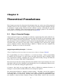
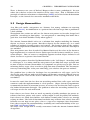
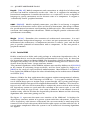
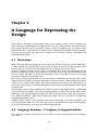
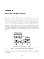
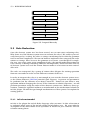
model
detection
strategies
source-code
design flaw
candidates
filters
metrics
Figure 2.1: Detection Strategies
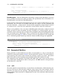
In the figure 2.1 it is presented the detection strategy approach to finding design
problems. The source code is parsed and a model of it is produced. The model is an
instance of the meta-model used for source-code analysis and detection strategies.
The model is then analyzed with the detection strategies and the flawed entities are
detected. These entities are then inspected at the source-code level and repaired.
Chapter 3
State Of The Art
In this chapter we enumerate the tools developed for quality assurance and software
architecture, specifically architecture description languages quality assessment tools
such as iPlasma [MMM+ 05] and Moose [NDG05]. In this chapter the Eclipse platform is also described along with all the plugins that are at the foundation of the
inCode.Rules plugin.
3.1
Quality Assurance Tools
This section will provide an insight on the tools used for specifying software architecture. We first start with the Architecture description languages, then we talk about
the DSM (dependency structure matrix) of the Lattix tool, the Semle and SCL tools.
And finally we describe two quality assurance platforms Moose and iPlasma.
3.1.1
ADLs
Architecture description languages are programming languages, usually domain specific languages that were designed to allow the specification of the architecture. Some
of the languages were developed for general-purpose architectures, while others were
targets at a more specific domain. We will enumerate and shortly describe a number
of these languages.
Aesop [GAO94]: Supports the specification of component intefaces, Each interface
is called a role, enforces stylistic invariants, behavior preserving style sub-typing,
graphical description of the underling model, it generates C++ code.
C2 Interfaces are represented with ports while methods are called ”messages”, provides ad advanced sub-typing mechanism to support architecture evolution, it explicitly supports connectors, it only restricts the number of component ports that can be
attached to each connector port, provides graphical notation.
Darwin [MDEK95]: Supports parameterized component types, connectors are called
bindings and are specified in-line, it cannot enforce constraints, it can be a bit hard
to understand due to the in-line specification of connectors, it supports runtime replication of components via dynamic instantiation as well as deletion and rebinding of
components via scrips.
16
3.1. QUALITY ASSURANCE TOOLS
17
Rapide [LKA+ 95]: Models components and connections at a high level of abstraction
and does not link the architecture to the code. Like C2, it supports the modeling of
hierarchical components. It models the interfaces as constituents. It uses an algebraic
language to specify constraints on the abstract state of a component. It support a
”semantically sound” graphical notation.
SADL [MQR95] : Models explicitly connectors, just like C2 and Aesop, it supports
refinements of connectors across styles and levels of abstraction. Like Aesop, it allows
the specification of invariants corresponding to different styles. The refinement maps
constrain valid configuration refinements. SADL and Rapide provide refinement and
specifications traceability.
Wright [AG94] : Formalizes the semantics of architectural connections. It is and
implementation independent language, as it does not put constraints on the implementation of the architecture. A components interface is called a ”port” and for each
port it specifies protocols of interactions with a component. It does not provide a
graphical notation.
3.1.2
Lattix LDM
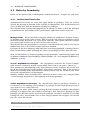
LDM is a tool used to define and verify package or subsystem dependencies rules. It
is a solution that is used in the industrial environment on a large scale. It’s based on
the Dependency Structure Matrix (DSM). The Dependency Structure Matrix was first
developed and widely used in the analysis of manufacturing processes where it can
also be found by the name ”design structure matrix”.
”The potential significance of the DSM for software was noted by Sullivan et al [SGCH01],
in the context of evaluating design tradeoffs, and has been applied by Lopes et al
[LB05] in the study of aspect-oriented modularization. MacCormack et al [MRB06]
have applied the DSM to analyze the value of modularity in the architectures of Mozilla
and Linux.”[Lat]
However, LDM is the first application that supports explicit management of software
entities dependencies. The advantages of LDM are : a very good scalability (it still
needs 1GB of heap-space to analyze large system though), and a pretty good integration with the Eclipse Integrated Development Environment. LDM has a few disadvantages as well : the user needs to manually re-analyze the source-code in order to keep
the dependency matrix in synch with the evolution of the source-code, it can only
enforce and verify one type of rule - one entity is allowed or is not allowed to access
another entity, and the fact that the Dependency Structure Matrix and the clustering
algorithms take some time getting used to.
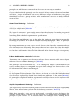
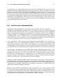
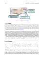
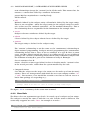
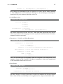
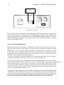
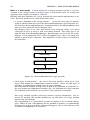
The figure 3.1 represents the main user interface of the LDM tool. It displays the
dependency structure matrix of a generic system with four subsystems. In order to
add a dependency rule between subsystems the user must make a mind map of the
names and ids of each subsystem, then find the right square and then add the rule. It
can get more complicated when the system is no so trivial and clustering algorithms
are applied.
!"#$%&'&()*&+,#-&./&012,1"1$.&(1"#%$&0341"&
!
18
B2#!"CD!&1%A!/1.@%A#$!9!/.E#1F)*!E90!3.!@%$)9**0!1#/1#$#'3!32#!1)*#$>!G#!)$#!&1##'!
9'A!0#**.E!31%9'&*#$!93!A%FF#1#'3!@#13%=#$!.F!32#!=#**!3.!%'A%=93#!E2#32#1!9!A#/#'A#'=0!
CHAPTER 3. STATE OF THE
%$!/#1H%33#A>!!I.1!9!!"#$%&'!1)*#;!32#!=#**!29$!9!&1##'!31%9'&*#!%'!32#!)//#1!*#F3!
@#13#:J!9'A;!F.1!9!!"##()$%&'!1)*#;!32#!=#**!29$!9!0#**.E!31%9'&*#!%'!32#!*.E#1!*#F3!
@#13#:>!<F!32#1#!%$!9!A#/#'A#'=0!%'!9!=#**!&.@#1'#A!K0!9!!"##()$%&'!1)*#;!E#!$2.E!%3!
E%32!9!1#A!31%9'&*#!.'!0#3!9'.32#1!@#13#:!.F!32#!=#**!L)//#1!1%&23M>!
ART
!
Red Triangle
Indicates that
Design Rule has
been violated
Green Triangle Indicates that
Dependency is allowed
Yellow Triangle Indicates
that Dependency is not
allowed
!
!
&
Figure 3.1: DSM matrix [Lat04]
5#%3,1&67&(121$-1$8#1"&'$-&0341"&#$&.91&()*&+,#-&
!
3.1.3
B2#!)$#!.F!9!"CD!F.1!1#/1#$#'3%'&!A#$%&'!1)*#$!%**)$3193#$!0#3!9'.32#1!K#'#F%3!.F!32#!
Moose
"CD!&1%A>!N@#10!#*#H#'3!.F!32#!&1%A!1#/1#$#'3$!A#$%&'!%'3#'3>!B2#!319A%3%.'9*!
1#/1#$#'393%.'!E2%=2!1#*%#$!.'!A%1#=3#A!&19/2$!K#=.H#$!=*)33#1#A!9'A!
”Moose is%'=.H/1#2#'$%K*#!E2#'!)$#A!O)$3!F.1!$2.E%'&!A#/#'A#'=%#$>!P$%'&!9!A%1#=3#A!&19/2!
a language-independent environment for reverse and re-engineering com3.!$2.E!A#$%&'!%'3#'3!E.)*A!K#!#@#'!H.1#!A%FF%=)*3!9$!9!*%'#!$#&H#'3!E.)*A!K#!
plex software
systems. Moose provides a set of services including a common meta1#Q)%1#A!K#3E##'!#@#10!$)K$0$3#H!3.!#@#10!.32#1!$)K$0$3#H>!
model, metrics
evaluation and visualization, a model repository, and generic GUI sup8933%:!F)132#1!%H/1.@#$!)/.'!32%$!@%#E!K0!9**.E%'&!)$#1$!3.!=*%=R!.'!9'0!=#**!3.!$##!
port for querying, browsing and grouping. The development effort invested in Moose
32#!9=3)9*!A#/#'A#'=0;!1)*#!9'A!1)*#!@%.*93%.'>!B2#!&1%A!'9@%&93%.'!%$!$%H/*#!9'A!
has paid%'3)%3%@#>!<3!%$!$%H/*#!F.1!)$#1$!3.!A1%**!A.E'!%'3.!9'0!$)K$0$3#H!3.!%A#'3%F0!#:9=3*0!
o in precisely those research activities that benefit from applying a combination ofE2%=2!$)K$0$3#H!%$!1#$/.'$%K*#!F.1!@%.*93%'&!32#!A#$%&'!1)*#>!
complementary techniques” [NDG05].
The moose platform is a very open and extensible tool. At its core lies a meta-model
that is used for source-code analysis. But, if this meta-model needs to be extended, it
can be very easily because the meta-model itself is described by a meta-meta-model.
Some of the tools based on Moose are : Fame -the meta model engine of Moose, Mondrian - scriptable visualization engine, EyeSee - scriptable charts engine, DynaMoose
- dynamic analysis tool, Chronia - CVS analysis of code ownership, Hapax - source
!!"#$%&'!()*#$!
+!,!+! -./01%&23!4556+7!8933%:;!<'=>!!?**!1%&23$!1#$#1@#A!
code vocabulary
analysis, SCG Algorithm - algorithms and vector/matrix classes for
!
Visual Works, SmallDude - duplication detection.
3.1.4
iPlasma
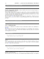
”iPlasma is an integrated environment for quality analysis of object oriented software
systems that includes support for all the necessary phases of analysis: from model extraction (including scalable parsing for C++ and Java) up to high-level metrics-based
analysis, or detection of code duplication. iPlasma has three major advantages: extensibility of supported analysis, integration with further analysis tools and scalability”
[MMM+ 05].
iPlasma is a platform that is the base for numerous tools designed for quality assurance. Some of these tools are : Memoria, a meta-model that is language independent
SAIL - a domain specific language designed to implement structural analyses, Dude :
a tool designed to detect code duplications, jMondrian - a visualization tool. The user
interface of iPlasma is also worth mentioning: Insider is built to allow users to access
Romania
{lrg}@cs.utt.ro
3.2. ECLIPSE AS A CODE ANALYSIS PLATFORM
2
19
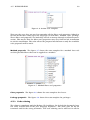
Overview
all the metrics and plugins defined in iPlasma through the UI. Further more, Insider
is open implemented, this means that the UI does not need to be changed if a new
1
er, a superior quality
of or tool Figure
1 presents
the layeredloads
structure
of iPlasma
analysis
is added,
it automatically
it and
displays itquality
to the user.
must be ensured. For
upported by automated
ign improvement, at a
source code. iPlasma
ity analysis of objectsupport for all the necl extraction (including
p to high-level metricslication. iPlasma has
of supported analysis,
and scalability, as it
cale projects in the size
and Mozilla).
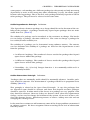
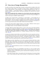
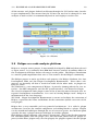
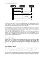
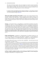
assessment platform. Notice that the tool platform, starts
Figure 1. The
iPlasma
analysis platform
Figure
3.2: iPlasma
directly from the source-code (C++ or Java) and provides
ility and the flexibility
the complete support needed for all the phases involved in the
3.2 Eclipse
asprocess,
a code
analysis
design and implemenanalysis
from
parsing theplatform
code and building a model
r this purpose a lot of
up to an easy definition of the desired analyses including even
Eclipse
open source project. It was initially developed by IBM and then released
the art literature.
Inis an the
detection
of code duplication, all integrated by a uniform
as
open
source.
It is estimated that IBM had invested around 40 million dollars in
systems we need a set
front-end, namely insider.
the development of Eclipse before releasing it to the public. The Eclipse Foundation
Through
the next
paragraphs
we stewart”
are going for
to briefly
intro-community.
is a not-for-profit
corporation
that
acts as ”the
the Eclipse
duce the main components of the iPlasma quality assessment
intend to present the
platform.
. Based on a The
“handsEclipse project
is made up of three sub-projects: the Eclipse Platform, the Java
how this suiteDevelopment
of tools
Tools and the Plugin Development Environment. These three sub1 iPlasmaall
alyses that assess
the are basically
projects
that
neededPlatform
to buildforall
the other
tools,
stays
for is
integrated
software
modelling
and or plugins as
are systems. they are called.
analysis.
The Platform is a core component of Eclipse. It provides (among others) the user interface - the SWT component, and the file system interface - the Resources Plugin.
The Java Development Tools plugin is one of the (if not the) most advanced Java integrated development environments. It is used to develop Eclipse itself - Eclipse is
implemented in the Java language.
The PDE - Plugin Development Environment is meant to facilitate the extension of
Eclipse, it provides the Views and Editors for the connection (called extensions of the
new plugins.
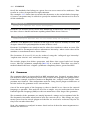
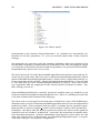
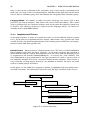
Eclipse has a very extensible and very powerful architecture. It is called a plugin
architecture, because the smallest component, or building block is a plugin. Plugins
can be contributed to Eclipse through the use of extension points. An extension point
specifies the way a plugin connects to Eclipse or to other plugins.
Each Eclipse plugin contains a file named ”plugin.xml”. This is the file that contains
the extension points that the plugin uses, the extension points that the plugin exports (so that other plugins may use this plugin), the plugins required for this plugin
20
CHAPTER 3. STATE OF THE ART
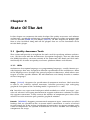
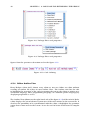
to work, and the exported classes and interfaces of this plugin.
Plugin Development
Environment
Eclipse Modeling
Framework
Java Development
Tools
Eclipse Platform
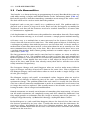
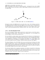
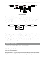
Figure 3.3: Eclipse Platform
The figure 3.3 also displays a plugin called Eclipse Modeling Framework. This framework is very important to the development of the inCode.Rules language and will be
detailed in section 3.2.2. The next subsection details the Plugin Development environment.
3.2.1
Plugin Development Environment
The Plugin Development Environment provides the tool and infrastructure to develop
and deploy Eclipse plugins and RCP applications. RCP (Rich Client Platform) applications are Eclipse based applications that are not development environments, but
general java applications build using SWT and Eclipse.
The PDE also provides OSGi tools making it an ideal environment for component
programming, not just Eclipse plugin development. OSGi tools are the basis for the
development applications based on the OSGi dynamic module system for java.
The main components of PDE include :
• PDE build - Generates Ant build scrips using the information provided by plugin
implementors (plugin.xml, build.properties files).
• PDE UI - Provides builders, editors and views to ease the plugin development
process in the Eclipse IDE.
• PDE API tool - Eclipse IDE and build process integrated tooling to maintain
plugin API.
• PDE Doc - The PDE help, documentation and API for plugin developers.
3.2.2
Eclipse Modeling Framework
The Eclipse Modeling Framework was designed to enable programmers to model their
application first and then generate the code and other features. Modeling greatly reduces development time and also factors out the business model from the rest of the
3.2. ECLIPSE AS A CODE ANALYSIS PLATFORM
21
application: presentation, persistence, etc.
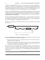
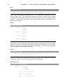
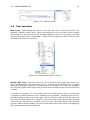
EMF itself supports three ways of defining a model : (i) Annotated Java code (ii) XML
files (iii) UML schemas build with various UML plugins for Eclipse like Rational Rose
or EclipseUML.
UML
EMF
Model
Java
Annotations
XML
Figure 3.4: EMF unifies UML, Java and XML [BBM03]
Having the written the EMF model in one of the three ways, the developer generates
the following features with the aid of the EMF: (i) A set of java classes, also known as
the Meta-model to be used when building the model, (ii) a set of adapter classes used
when viewing and programatically editing the model, (iii) a basic editor of the model.
3.2.3
Java Development Tools
The Java Development Tools project provides the most features needed for sourcecode quality assurance tools. It has three main components: the Java Model, the
Search Engine and the Abstract Syntax Tree.
The Java Model is a light-weight representation of the Java Projects. It it implemented
in such a way to allow easy navigation, type hierarchies, basic modifying operations,
code completion, resolving etc. even for large scale projects (e.g: 10.000 types). The
Java elements in the Java Model are wrapped by the inCode 3.2.5 plugin. Each entity
in the meta-model of inCode wrapps a different element from the Java Model1 .
The Search Engine in the JDT allows the user to search for java elements by using
regulated expressions. It has a very configurable and powerful user interface in the
Eclipse IDE, but more importantly (to this work) it has an API that allows other plugins to programmatically search for java elements. This feature is heavily used by the
inCode.Rules plugin in order to retrieve java elements.
The Abstract Syntax Tree component provides the features required by refactoring
tools, by Quick Fix and Quick Assist. The Abstract Syntax Tree creates a tree out of
plain java code and thus allows for a more convenient and reliable way to inspect and
change the source-code than a plain text based approach.
1 Except for local variables, method parameters and other entities that are declared inside the method
body: these entities wrap AST nodes.
22
CHAPTER 3. STATE OF THE ART
3.2.4
Xtext
Xtext is a framework used for the development of Domain Specific Languages (DSLs).
Xtext is based on the Eclipse Modeling Framework, and it integrates technologies
such as : Graphical Modeling Framework, Model to text (M2T) and some parts of the
Eclipse Modeling Framework Technology.
In order to use Xtext it is necessary to write the grammar with the Xtext notation,
then allow Xtext to generate the features. Xtext derives from the grammar:
• An incremental, Antlr 3 based parser and lexer.
• Ecore-based meta models.
• A serializer, used to serialize instances of meta-models back to a textual representation that can be reparsed.
• A Linker.
• An implementation of the EMF Resource interface - based on the parser and the
serializer.
• Full fledged integration of the language in the Eclipse IDE: syntax coloring, navigation, code completion, outline view, code templates.
3.2.5
inCode
inCode is an Eclipse plugin that provides developers with the support for the detection and correction of design flaws. It was derived from the iPlasma tool 3.1.4 and it
shares its meta-model and some of its detection strategies, while others were tweaked.
However, unlike iPlasma, inCode allows the detection of design flaws in real time. The
programmer is warned immediately after the file save that a design flaw has been
detected.
The user is warned via a red square (a marker) that appears on the left-hand-side
Editor ruler right next to the java element where the design flaw has been detected.
inCode can also analyze the entire project on demand. To do so, it has two views: the
Overview Pyramid, the Sight View and the Architectural Design View.
The Overview Pyramid describes the overall structure of an entity(workspace, project,
source folder or folder) by quantifying the aspects of complexity, coupling and usage
inheritance. On the left there is an implementation of the Overview Pyramid described
in [LM06] and on the right there’s a summary of all the detected design problems.
inCode Sight is a metric-based view that shows you in one-shot the essential traits
(e.g. dependencies) of an Eclipse entity (system, package, class, method, attribute)
using software visualizations. inCode Sight lets you explore the visualizations in detail. Hence, if the user wishes to examine a visualization more carefully, he can right
click on the corresponding entity and invoke the corresponding action from the drop
down menu.
The Architectural Design Problems View detects design flaws in terms of the systems
structure, analyzing relationships between components (packages or subsystems).
3.2. ECLIPSE AS A CODE ANALYSIS PLATFORM
23
inCode can detect packages or subsystems that suffer from the following design problems : Stable Abstraction Principle violation, Cyclic dependencies and Stable Dependency Principle violations.
Chapter 4
A Language for Expressing the
Design
This chapter describes the language from a user’s point of view. It first explains the
main concepts from which the language was derived. Then a more detailed description of the structure of the language is made, with an emphasis on the features and
limitations. Next, the grammar is analyzed for a complete description of the language.
Last but not least the user interface is shown and described, mainly: the Editor and
the BrokenRulesView.
4.1
Motivation
Why a Domain Specific Language to describe the Design of Object Oriented Software
? Why should one (re)code the design of the system in another language other than
the one that is used to actually implement the system (Java in this case).
At first, it might seem absurd to code and maintain two design specifications (in two
different languages) of the same system. In addition there’s the documentation of the
system, which also has to fit in the equation in the sense that it needs to be kept
consistent with the production code.
But, if the design specification can be maintained automatically during code development then one of the problems mentioned above is solved. This problem has been
addressed by all the other tools. The other problem, concerning the differences between the code (design or actual production code) and the documentation still remains
unaddressed.
inCode.Rules solves both problems by being in contact with both worlds - production
code and Documentation. The code-design problem is solved like all the other tools,
while the code-documentation problem is solved due to the fact that the language is
very ’human readable’. This means that the design code can actually be included in
the Documentation itself.
Another major reason is the fact that because the language is ’human readable’, it is
very easy to work with. The user does not need to spend time learning a new language,
or try to understand a new way to present dependencies.
4.2
Language Anatomy / Categories of Supported Rules
The language supports two different sets of rules: usage/relationship rules and property rules.
24
4.2. LANGUAGE ANATOMY / CATEGORIES OF SUPPORTED RULES
25
The usage/relationship rules are meant to provide the designer the ability to breakdown the system into components, or modules. Also, they are meant to let the designer to specify the usage relationships between the components. The beauty of this
rule type is that you can define components that overlap, thus allowing the designer
to specify more than one modularization of the same system.
Property rules on the other hand have another role, they allow the designer to enforce
rules using filters and properties that are already defined in inCode.
4.2.1
Use rule
The idea behind the first type of rule is that the designer has to be able to specify how
the packages (or subsystems, (or entities) ) of a system interact and relate to each
other. The rule is composed of three parts : Subject, Action and Target.
A very simple example of this type of rule is:
Listing 4.1: Rule Example
package named "X" must not use package named "Y" ;
It should be obvious what the rule says: Package X is not allowed to know anything
about package Y. Now let’s analyze it from the ’Subject Action Target’ point of view.
The subject : package named ”X” defines package ”X”. This is the entity that the rule
refers to. The rule can be broken only by changing package X so that it uses package
Y.
The target : package named ”Y” defines package ”Y”.
The action : must not use defines the relationship that the Subject must obey.
The subject and the target have the same grammar : they can be interchanged and
the rule would still ”compile”. The only differences are:
1. who takes the blame if the rule is broken and, more importantly,
2. the semantics of the rule, X can not use Y, but Y can use X.
Subject Further analyzing the subject (or the target) in the example:
package named ”X”
The first word ”package” refers to the type of entity this subject refers to. inCode.Rules
now supports only three types of code entities : packages, classes and methods.
The second part of the subject is called a filter. The filter is responsible for choosing
which of the packages of the current system (the java project that contains the rule
file) will make up the subject of this rule. The filter in this example is a ”named” filter.
The named filter chooses the packages (in this particular instance) by eliminating the
ones that do not comply with the REGULAR EXPRESSION inside the following quotes.
The language supports other types of filters as well :
• Being filter
classes being ”Data Class”
The ”being” filter uses an existing filter (this filter takes one parameter - a string,
just like the ”Named” filter) that is part of the inCode plugin. One example of
26
CHAPTER 4. A LANGUAGE FOR EXPRESSING THE DESIGN
this kind of filter is ”Data Class”. The filter delegates the work to inCode. More
details on how this works in the next chapter. // should be a link here
• From filter
classes from ”org.eclipse.ui.*”
The ”from” filter works almost like the ”named” filter : it uses a regular expression to find java elements. It searches for the type of java elements that contain
elements specified in the first word of the subject. For example : [ classes from
”X” ] searches for packages that comply with the regular expression ”X” and then
returns all the classes in that package. Another, more complex example would
be : [methods from ”Y” ] here the plugin first searches for packages that match
the Regular Expression ”Y” and if it finds at least one, it returns the methods in
those packages (that package). If no package is found then the methods that belong to the classes whose names match the ”Y” regular expression are returned.
More on this matter can be found in Chapter 5 section x.
• Composed filter
classes from ”org.eclipse.ui.*” and named ”*Dialog”
A composed filter is a way to combine two filters (a composed filter, is still a
filter, mind you). Two operators are used to combine filters: ”and” and ”or”. The
”and” operator means that the two filters must be applied in series, i.e. all of the
returned elements respect both filters. While the ”or” operator applies the two
fields in parallel, i.e. every one of the returned elements must respect at least
one of the filters.
The subject non-terminal is summarized in the syntax diagram 4.1.
package
being
packages
from
class
named
classes
Composed
String
method
methods
Figure 4.1: subject or target
Action The action is composed out of two parts: the rule type specifier, ’must’, ’must
not’, ’may’ and type of relation. The rule type specifier is one of the key words ”must”,
”must not” or ”may”.
The type of relation can be :
• use
Subject entity references target entity directly or entities contained in subject
entity reference entities contained by the target entity e.g. : methods in a class
reference attributes in a package. Limitation: this relationship relies on the
4.2. LANGUAGE ANATOMY / CATEGORIES OF SUPPORTED RULES
27
next relationships (except for ”contain”) to do all the work. This means that, for
instance, a constructor called by a attribute declaration :
private MyClass myAttribute = new MyClass();
will be missed.
• call
Methods defined by the subject entity call methods defined by the target entity.
There is one exception : when the target entity (or the subject entity) are methods, in this case the ”methods contained”, are the methods themselves. This is
the relationship that is responsible for the limitation in the example above.
• access
Subject references attributes defined by the target.
• inherit
Classes defined by the subject inherit classes defined by the target.
• contain
The target entity is declared in the subject entity.
The ”contain” relationship is not the same as the ’containment’ relationship in
object oriented programming. In object oriented programming the ’containment’
relationship means that a class A has an attribute of a type B. But, in most
cases, type B is defined outside the class A, in a different type, or even a different
package. The ”contain” relationship means that if entity A contains entity B, then
the definition of entity B is part of the definition of entity A. Example :
class A contains class B
means: class B is a inner-type defined in class A. In other words, ”contain” refers
to the actual java code, rather than the system modeled by the code.
• Composed Action
Just like the subject or the target, the action can be made up of two (or more)
actions. There are two operators with which the user can compose actions: ”or”
/ ”and”. For instance, if we would like to make sure that no call nor access is
made from package a.b to package x.y :
Listing 4.2: Composed Action Rule
package named "a.b" must not ( call or access ) package named "x.y ";
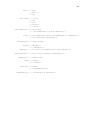
The figure 4.2 is a summary of the action non-terminal:
4.2.2
Have Rule
The Have rule is an asymmetric type of rule. It is made up of a subject and an action.
The subject is exactly the same as with the ’use rule’ but the action is different. The
action only supports one verb : have. An example is in order :
Listing 4.3: Have Rule
classes must not have " Data Class ";
28
CHAPTER 4. A LANGUAGE FOR EXPRESSING THE DESIGN
Subject
must
contain
must not
use
may
call
Target
access
inherit
Composed
Figure 4.2: action
The rule says that the system is not allowed to contain any classes that are ’data
classes’. ’Data Class’ is a Filter implemented in inCode and describes classes that
”are dumb data holders without complex functionality but other classes strongly rely
on them” [LM06]. The rule can be read as : ” subject action ’Property String’ ”, where
”Property String” has to be an inCode defined Property or Filter and the action can
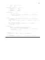
only use the verb ’have’.
Subject
must
have
Property
must not
may
Figure 4.3: have rule
These ’property strings’ have been defined in the Object Oriented Metrics in Practice
book as ”Identity Disharmonies”[LM06]. Even though the reader is encouraged to read
the book, in Appendix A there is a list of all the possible string values that can be used.
The ’Property String’ can be replaced by an expression composed of two or more
strings. The properties can be combined with the aid of the two operators that help
construct subject or action expressions : ”or” / ”and”. This allows us to write more
complex ’have rules’:
Listing 4.4: Composed Filter
classes must not have ( " Brain Class " and " God Class " );
4.2.3
Exception Mechanism
”Rules are meant to be broken”.
This saying holds in no other engineering field better than in software development.
Change is an intrinsic property of software. It would be foolish to think that if a set of
design decisions (let alone rules) will be valid and respected throughout the entire life
4.2. LANGUAGE ANATOMY / CATEGORIES OF SUPPORTED RULES
29
of the system.
This is the main reason why the language supports the concept of Exception. So that
if the design is flawed, or if it needs to be changed there is a way of modifying it in
an elegant manner. Exceptions also allow the design (i.e. the rules file) to be kept as
consistent as possible with the code.
The other reason for the introduction of Exceptions is the fact that they allow a much
simpler design. For instance, consider a package ’org.x’ with four classes A, B, C and
D. The design states that package ’org.x’ is not allowed to use package ’org.y’ except
for class D. If exceptions did not exist we would have to write three rules to code the
design, one for each class except class D. With exceptions we only need to write one
rule and one exception. At first this might not seem that much of an improvement,
but what if package ’org.x’ contained 10 classes, or 20 classes ? It is clear that the
language would simply not scale without the concept of rule exceptions.
Exceptions are an optional part of a rule and they appear after the rule definition,
between braces, and before the semicolon.
Let’s take a look at an example :
Listing 4.5: Exception
package named " org .x" must not use package named " org .y"
except {
class named " org .x. ThisClass "
may use class named " org .y. ThatClass " };
One cannot help noticing that the exception looks a lot like a rule. Actually, grammatically speaking, exceptions are rules. It is the way they are interpreted is what makes
them exceptions. There is one constraint that applies to exceptions : their action has
to be opposite or neutral to the action of the rule. For example, if the main rule is
a ”must not” rule than every exception this rule has must use the ”may” or ”must”
qualifiers of their action.
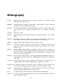
rule
must
must not
exception
may / must not
may / must
Since exceptions are, in essence, rules this means that they too can have their own
exceptions. Let’s take up an example : package org.x is not allowed to use package
org.y. However, class org.x.A is allowed to use package org.y, ...except for method ’foo’
of class org.x.A: method ’foo’ is not allowed to use package org.y. The code is quite
simple :
Listing 4.6: Exception with exception
package named " org .x" must not use package named " org .y"
except {
class named " org .x.A"
may use package named " org .y"
except {
method named " org .x.A. foo "
must not use package named " org .y "}};
30
CHAPTER 4. A LANGUAGE FOR EXPRESSING THE DESIGN
Of course, this mechanism is recursive, the user can write as many imbricated exceptions as he/she likes. Having that said, it is not that easy to write exceptions (that
also make sense) on more than four levels. It is also not recommended to use the
exception mechanism in this manner (more than 4-5 levels of imbrication) because of
the increased complexity of the rule, which diminishes its understandability.
Given the fact that exceptions have the action qualifier opposite or neutral to the rule
qualifier, and the fact that exceptions can have their own exceptions: if we write an
exception with the ’may’ qualifier, what will its exceptions use as an action qualifier ?
The answer is pretty straight forward : the qualifier is the same as the rule above the
exception with the ’may’ qualifier.
Because the language supports two types of rules : use rules and have rules, there
are two types of exceptions as well. Actually since exceptions are rules, it is quite easy
to remember that use rules can only have exceptions that are use rules, and likewise,
have rules can only have exceptions that are have rules.
The figure 4.4 explains the exception mechanism. This syntax diagram refers to both
types of rules.
Rule
except
{
Exception
}
Figure 4.4: exception mechanism
A few recommendations on how to use the exception mechanism so that it will work
in your favor instead of just complicating things:
• Keep exception imbrications at a minimum, three or four levels should be the
maximum any rule should have.
• When writing an exception, the designer usually refers to a subset of the target
or subject, it is OK if you just write the new subject and copy the rest of the rule.
Don’t forget to change the action qualifier though.
There are, however two exceptions of the exception mechanism described earlier: (i)
if a Rule has only one exception, that exception does not need to be surrounded
by braces, and (ii) a have rule exception can be composed of only a subject, it does
not need an action and a property. E.g. in the listing where both exceptions are
demonstrated.
Listing 4.7: Exception with exception
package named " org .x" must not have " Data Class "
except class named " org .x.A ";
4.3. RULES BY GRANULARITY
4.3
31
Rules by Granularity
Rules can be divided into 3 subcategories architectural level , design level, code level.
4.3.1
Architectural level rules
Architectural level rules are rules that apply mostly to packages. They are used to
specify the layering or division of the systems in components. The architectural level
rules usually start with the keywords package or packages.
The division of the system into components of modules is done so that the architect
can maintain the traceability of the specifications right down to the code level.
Multiple views The inCode.Rules language allows the architect or designer to specify multiple views of the same system. This is because the same java elements can be
included in more than one rule, even in the same file. This means that the designer
can specify two or more sets of rules for the same system.
This means that the programmers can better understand the role that a class has to
fulfill if that class is described in more than one location.
Packages in the java language allow only one structuring (through a naming convention), inCode.Rules allows grouping the classes or packages in more than one way.
Next, we will reiterate a couple of package design principles ”conceived by people such
as RobertCecilMartin, BertrandMeyer, BarbaraLiskov, etc. and compiled by RobertCecilMartin” [c2P08].
Acyclic Dependencies Principle ”The dependency structure for released component must be a Directed Acyclic Graph (DAG). There can be no cycles.” [Mar97a]
This principle (of not allowing cyclic dependencies) can be respected by careful coding of the rules that govern the package dependency structure. This is the preferred
method of avoiding cyclic dependencies, because in this way the control is very strict
and cyclic dependencies can not happen.
Another method, more accessible way, would be to write a have rule using the filter
”Cyclic Package Dependency” and applying it to all the packages.
Stable Dependencies Principle The dependencies between packages should be in
the direction of the stability of the packages. A package should only depend upon packages that are more stable than it is.
A package A is more stable than a package B if the number of packages that depend
package A is higher than the number of packages that depend on package B. This
principle,just like the Acyclic dependencies principle can too be avoided by carefully
coding the rules, but to make sure it does not get violated the designer can include
the rule 4.8 in the rule file:
Listing 4.8: SDP Violation
packages must not have " SDP Violation ";
32
CHAPTER 4. A LANGUAGE FOR EXPRESSING THE DESIGN
Stable Abstractions Principle Packages that are maximally stable should be maximally abstract. Unstable packages should be concrete. The abstractness of a package
should be in proportion to its stability.
This principle too, is already defined in inCode, as a filter, and can be used to write
rules:
Listing 4.9: ”SAP Violation” fiter
packages must not have " SAP Violation ";
classes being " is abstract " must not use classes being " is leaf - class ";
We can write rules like the second rule in the listing 4.9. These rules do not enforce the principle to the letter, but they might catch some flagrant violations of the
principle. Also, by defining the system layers so that each layer communicates with
another layer through the use of well defined interfaces the principle can be respected.
Reuse Release Equivalence Principle ”In order to effectively reuse code it must
arrive in a complete, black-box, package that is to be used but not changed. Users of
the code are shielded from changes to it because they can choose when to integrate
changes from the package into their own code. While this supports code ownership,
and even promotes it, it does not enforce it”.[Mar97a]
This principle can be coded in a rule file, indirectly, by enforcing the dependency on
abstract classes and interfaces, but not on concrete classes. I can not be enforced by
writing rules because it implies multiple versions of the same package.
Common Reuse Principle ”The classes in a package are reused together. If you
reuse one of the classes in a package, you reuse them all”[Mar97a].
This principle can be coded with inCode.Rules by writing something like the code in
listing 4.10. It states that package org.x is unaccessible to all other packages, except
to package ”org.y”. It also says that package ”org.y” must use all the classes from
”org.y”. Of course, this rule has to be written for all the packages that must respect
this principle. Also, it is clear that a package will rarely use all the classes in a package, but the exception can have exceptions too.
Listing 4.10: Common Reuse Principle
packages must not use package named " org .x" except
package named " org .y" must use classes from " org .x ";
4.3.2
Design level rules
Single Responsibility Principle There should never be more than one reason for a
class to change.[Mar03]
Using only structural analysis of the source code it is quite hard to determine if a
class conforms or not to this principle. This is because the principle implies knowing
4.3. RULES BY GRANULARITY
33
the business rules that the designers have implemented and, of course, they cannot
be obtained just by analyzing the dependencies among java elements.
One way to try to avoid violating this principle is not allowing any ”God Classes” or
”Brain Classes”. These are classes that have too many or too complicated methods
and that are centralize the system intelligence in one place. This is a very good indicator (of course this is not always the case) of the fact that these classes may violate
the Single Responsibility Principle.
In the listing 4.11 it is demonstrated how we can write just one rule that doesn’t allow
God Classes or Brain Classes to exist in the entire system.
Listing 4.11: Single Responsibility Principle
classes must not have (" God Class " or " Data Class ") ;
Open Closed Principle Software entities (classes, modules,functions, etc.) should
be open for extension, but closed for modification.
This principle can be coded by carefully designing the architecture, by allowing only
small and simple interfaces between packages and subsystems. It can not be coded
”as is” because it is a very wide principle that can be interpreted in many ways.
Liskov Substitution Principle ”Functions that use pointers or references to base
classes must be able to use objects of derived classes without knowing it.”[Mar96b]
This principle can be applied in part because to apply it in fully static code analysis
is not sufficient. It is possible to encode gross violations of this principle, for instance
:we can write rules that do not allow overriding methods to be NOPs.
Dependency Inversion Principle A. High level modules should not depend upon
low level modules. Both should depend upon abstractions.
Part A of this principle states that in a layer based architecture dependencies between modules should be ”interfaced” by abstractions. This is the main goal of this
language, to allow a clean architecture and module decomposition.
In listing 4.12 is listed a rule and one exception that encodes this principle, but it can
not be used as is, it must be adapted to the specific project.
Listing 4.12: Dependency Inversion Principle
packages must not use packages except
packages may use classes being " is abstract ";
B. Abstractions should not depend upon details. Details should depend upon abstractions.
Listing 4.13 encodes the second part of the Dependency Inversion Principle.
34
CHAPTER 4. A LANGUAGE FOR EXPRESSING THE DESIGN
Listing 4.13: Dependency Inversion Principle
classes being " is concrete " must not use classes being " is abstract ";
Interface Segregation Principle Clients should not be forced to depend upon interfaces that they do not use.
This principle states that if a client uses a given class, it has to use (almost) all of its
services. The solution to this problem is extracting an interface with only the services
used by the client. The violation of this principle also indicates that the class is also
violating the Single Responsibility Principle.
We can encode 4.14 this principle in the design by saying that a client has to use
all the services a class has to offer, and thus filtering out the classes that break this
principle.
Listing 4.14: Interface Segregation Principle
class named "X" must
4.3.3
use methods from class named "Y ";
Code level rules
Heuristic 4.1 Minimize the number of classes with which another class collaborates.
[Rie96b]
This heuristic has the role to keep the dependencies at a minimum. We can write a
rule 4.15 that says that a class should not collaborate with any other class and then
add exceptions as necessary.
Listing 4.15: H 4.1
class named "X" must not use classes except {
class named "X" may use class named "Y",
class named "X" may use class named "Z"
};
Heuristic 4.2 Minimize the number of message sends between a class and its collaborator.
This is practically the same heuristic as the above one, with the difference that it
refers only to methods. Instead o the keyword ”use” we can write ”call” and we obtain
the rule 4.16for this exact heuristic.
Listing 4.16: H 4.2
class named "X" must not call class "Y" except {
class named "X" may call method named " m1 ",
class named "X" may call method named " m2 "
};
Heuristic 4.6 Most of the methods defined on a class should be using most of the data
members most of the time.
This heuristic has the same role as the Single Responsibility Principle, it is required
4.4. GRAMMAR
35
for all the methods that belong to a given class to access most of its attributes. This
results to a class design that has tight cohesion.
The example 4.17 shows how to encode this heuristic in the inCode.Rules language.
Of course exceptions may be added to specify the methods that do not need to access
all the attributes.
Listing 4.17: H 4.6
methods from " MyClass " must access class MyClass ;
Heuristic 5.2 Derived classes must have knowledge of their base class by definition,
but base classes should not know anything about their derived classes.
Listing 4.18: H 5.7
classes being " is abstract " must not use classes being " is concrete ";
Heuristic 5.12 Explicit case analysis on the type of an object is usually an error. The
designer should use polymorphism in most of these cases.
Heuristic 5.13 Explicit case analysis on the value of an attribute is often an error. The
class should be decomposed into an inheritance hierarchy, where each value of the
attribute is transformed into a derived class.
The heuristics 5.12 and 5.13 can be enforced using the ”collapsed type hierarchy”
”explicit state checks” and ”embedded strategy”.
The inCode plugin also defines properties and filters that regard code level design
issues, like the cyclomatic complexity [McC76] of a method. This filter says that a
method should not have a higher cyclomatic complexity than a given threshold.
4.4
Grammar
The grammar (listed in Appendix B in BNF notation) was designed starting from a
few sentences that covered pretty much every feature the language was going to have.
From those example sentences (written in English) the ”subject action target” composition was factored. This composition and the string based plugin architecture of
inCode lead to the grammar in it’s current form.
One of the main goals of the language is that it should be as close to the natural
language as possible. This and the need for a simple, easy to understand and learn
Domain Specific Language (DSL) are the two main forces that shaped the grammar.
The terminals of the grammar are mostly keywords, strings and an optional rule ID.
The keywords determine what kind of rule the current rule is. The strings are arguments passed to the inCode plugin and the IDs are used to be referenced by the UI,
they have no other than that.
Next, the grammar is analyzed in more detail and to do that the more important terminals are discussed.
36
CHAPTER 4. A LANGUAGE FOR EXPRESSING THE DESIGN
• Rule:
Listing 4.19: Rule
Rule ::= ID ? Entity FilterExpression ? Action Target ;
This is the most important grammar rule. It is common to both the ’use rule’
and the ’have rule’. The difference between the rules is made by the Target
non-terminal. The Action non-terminal contains only the rule type (or the action
qualifier : must, must not, may), because the action itself is described by the
Target non-terminal.
• Entity :
Listing 4.20: Entity
Entity ::= Package
::=
Class
::= Method
Package ::= packages
::= package
Class ::= classes
::= class
Method ::= methods
::= method
The ’Entity’ non-terminal describes only the type of entities this rule deals with:
packages, classes or methods. Note that package and packages are one and the
same, they both exist purely for the sake of readability. Of course, the same goes
for class/classes and method/methods.
• Target :
Listing 4.21: Target
Target ::= ActionExpression Entity FilterExpression ? UseException ?
::= have HaveTarget HaveException ?
Here we can se clearly how the two rule types diverge. This solution was chosen
so that the subject and the action would remain common.
• FiterExpresion:
Listing 4.22: FilterExpression
FilterExpression ::=
::=
::=
::=
From
Being
Named
LeftParan
From ::= from EntityNames
Being ::= being STRING
Named ::= named EntityNames
4.4. GRAMMAR
37
LeftParan ::= ( FilterExpression Op FilterExpression )
Even though the FilterExpression is optional, few rules will be written without
it. The EntityNames non-terminal is a String, or a list of Strings containing the
name(s) of the java elements this filter refers to.
• ActionExpression:
Listing 4.23: ActionExpression
ActionVerb ::=
::=
::=
::=
::=
contain
use
call
accsess
inherit
ActionExpression ::= ActionVerb
::= ( ActionExpression Op ActionExpression )
The action expression for the ’use rule’. Note that this expression and all the
other expressions in the language are made up of two elements between brackets
composed with an operator.
• Exceptions - UseRule and HaveException
Listing 4.24: Exceptions
HaveException ::= except HaveEx
HaveEx ::= HException
::= { HException + }
HException ::= ID ? Entity FilterExpression ? HActionException ?
HActionException ::= Action have HaveTarget HaveException ?
UseException ::= except UseEx
UseEx ::= UseRule
::= { UseRule + }
These are the two types of exceptions. The use exception is the simple one, as it
simply re-directs to the UseRule. The Have exception is a bit more complicated
as the HaveRule could not be reused.
• HaveTarget
Listing 4.25: Have Target
HaveTarget ::= STRING
::= ComposedHaveFilter
CompHaveFilter ::= ( HaveTarget Op HaveTarget )
The Have Target is a string expression, its role is to combine the already defined
filters from inCode so that they can be applied to the subject of the Have Rule.
38
4.5
CHAPTER 4. A LANGUAGE FOR EXPRESSING THE DESIGN
Rules Editor
Code complete is invoked, just like in the Java Editor, by pressing Ctrl+Space while
writing rules. Because the language was designed to be as close as possible to natural
language, but also to be as simple as possible, a very good way of learning to write
rules is to use the content assist system.
4.5.1
Auto-complete - generated
From the grammar that I wrote, Xtext generates a content proposal system that is
able to determine which keywords could come next. This content proposal system
can work because the parser is a LL parser, this means that it can create a partial
AST of a rule, even if that rule is not complete. It can even create the AST (obviously
a incomplete AST) of a rule that has only the first word.
After creating the AST the content proposal system can easily determine which of the
keywords (or other grammar elements, like strings, or semicolon) could come next.
Subject / Target proposals In the figure 4.5, which is a screenshot of the inCode.Rules Editor, it is demonstrated the capability of the content assist system to
determine the next possible keywords. It ’knows’ that after the keyword ”class” the
rule can continue with the optional filter (and it proposes ”(”, ”named”, ”being”, ”from”)
or directly with the action (and it adds to the proposed keywords the ”may” and ”must”
options).
Because Xtext does not discriminate between filters and actions, the proposed keywords are sorted alphabetically.
Figure 4.5: Subject code complete
Action proposals The figure 4.6, is another screenshot of the inCode.Rules Editor,
this time taken while displaying the code complete when writing the action of a rule.
4.5.2
Smart auto-complete
The is however one problem, that Xtext does not resolve. The problem can not be
resolved just by looking at the grammar. It’s of course the matter of the strings that
represent java element names or the filter names that are passed to the inCode plugin.
Xtext alone can not complete these strings because it needs further information from
JDT or inCode. This is where inCode.Rules comes in, I have implemented the complete proposals that were missing in order to help the user write the rules more easily.
4.5. RULES EDITOR
39
Figure 4.6: Action code complete
This way the user does not need to remember all the filters and properties defined in
inCode for the three entity types the language can deal with : method, class, package.
These filters and properties are loaded by inCode at startup through a reflection mechanism. This means that the filters and properties may vary from inCode installation
to inCode installation. This also affects the proposal mechanism as only the available
code proposals will be made.
Method proposals The figure 4.7 shows the auto complete for a method have rule
and the possible filters that can be applied to a method.
Figure 4.7: Method filters and properties
Class proposals The figure 4.8 shows the auto complete for classes.
Package proposals The figure 4.9 shows the auto complete for packages.
4.5.3
Code coloring
The editor is compliant with the Eclipse UI Guidelines. By default the keywords have
the same default color of the java language keywords. The same goes for the ID
terminals and for the string terminals. The code coloring can be observed in all the
40
CHAPTER 4. A LANGUAGE FOR EXPRESSING THE DESIGN
Figure 4.8: Package filters and properties
Figure 4.9: Package filters and properties
figures from the previous subsection and in the figure 4.10
Figure 4.10: Code Coloring
4.5.4
Editor Outline View
Every Eclipse editor (well, almost every editor as one can define an editor without
creating an outline for it) has its own Outline View. The Outline view has the role
to highlight the structure of the code (assuming the text in the editor is written in a
structured language, like a programming language, or a domain specific language) by
displaying organized as a tree.
The Outline View (shown on the right-hand side of the figure 4.11) of the inCode.Rules
editor displays the actual abstract syntax tree of the rules written in the current file. It
also has the possibility to be synchronized with the editor: it highlights the grammar
entity that is most near to the cursor. It can be used to better understand a complex
rule
4.6. USER INTERFACE
41
Figure 4.11: Editor outline
4.6
User Interface
How to run After writing the rules in a rule file, the rules can be checked for conformance with the source-code. To run the interpreter on a rule file we must simply
right click 4.12 the rule file in the Package Explorer View (Or any other view that
displays files) and select ”Check Rules”. Then the rule interpreter visits each rule and
determines if it has been broken.
Figure 4.12: Running the Rule Checker
inCode Tips View After the rules have been checked the inCode Tips View 4.13
opens automatically and shows the results. If there are no broken rules a simple
message is displayed saying so. If, however there are broken rules, they are displayed
in a list using either their names (ids) or their order number (if the rule does not have
a name).
As shown in the figure 4.13 the broken rules are enumerated in a list separated by
a comma and their names (or rule numbers) are hyperlinks. Clicking one of the hyperlinks brings up the tree on the right. The tree on the right side of the view is a
one level tree that shows the ”relations” that caused the rule to break. For example
if the rule was violated by a method call, in the tree, the name of the called method
appears. When double clicking the rule inCode.Rules opens the editor and highlights
the exact location of the method call.
42
CHAPTER 4. A LANGUAGE FOR EXPRESSING THE DESIGN
Figure 4.13: Broken Rules displayed in the inCode Tips View
Chapter 5
Execution Mechanics
The previous chapter provides the information needed to use the inCode.Rules language. It was, however, a black-box view of the inCode.Rules plugin. If the reader is
interested in the inner workings of the plugin then this is the chapter to read. First the
grammar is described, this time implemented in the Xtext grammar language. Next,
the generated code is analyzed and a high level schema of the application is shown.
We continue with describing what happens at run-time (the model that is instantiated
by the parser) and the implemented visitors (this is where the rules get verified).
The figure 5.1 displays a the architecture of the plugin and how it connects with other
Eclipse plugins. The grammar, which is described in the first section is included in
the ”Language Definition Block”. The section that describes the visitors contains the
Java elements search block, the Groups building block and the Language interpreter
block.
inCode.Rules
Broken Rules View
Language interpreter
Language
definition,
Editor
Java
elements
search
Groups
building
inCode
Xtext DSL Framework
Eclipse Modeling
Framework
JDT
Eclipse
Figure 5.1: The architecture of the inCode.Rules plugin
The first four sections describe the actual source code of inCode.Rules. They are ordered in the chronological order of their development. Having that said let’s start with
the grammar.
43
44
CHAPTER 5. EXECUTION MECHANICS
5.1
Xtext Grammar
As depicted in the introduction, the grammar must be written in the Xtext format.
This section will provide an insight into the development of the grammar and explain
the implemented solution.
5.1.1
Xtext grammar features used
Xtext comes with an already defined set of seven terminals. These terminals include
: ID used to write names of entities, STRING used to describe a string expression, WS
used to describe a white spaces or tabs or return carriers ( n).
Xtext also infers the meta-model from the grammar, this is done with the line 5.1:
Listing 5.1: generate EPackage
generate dsl " http :// www . intooitus . com / rules / dsl "
The line says to generate an EPackage with the name ”dsl”, this is how the grammar is
named in the implementation, and with the nsURI ”http://www.intooitus.com/rules/dsl”
- these are the parameters needed to create an EPAckage.
The grammar file is listed in Appendix C for reference purposes. It was written so that
it respects the requirements of the inCode.Rules language and also not to write it as
cleanly as possible, without duplicated code
5.1.2
Grammar definition
Here we shall take a deep dive into the grammar definition, and provide a detailed
expression of each of the rules. Each paragraph talks about a different grammar rule,
it contains the rule listed and also a short description of the chosend solution.
Rules At the root of the grammar we find the ”Rules” non-terminal 5.2. It exists in
order to allow the definition of multiple rules. The ”+=” assignment operator was used
so that the Rules non-terminal would contain a list of rules.
Listing 5.2: Rules
Rules :
( rules += UseRule ’; ’) *;
UseRule The ”UseRule” non-terminal represents the a rule. Both the use-rule and
the have-rule start here (the terminal should be renamed). The difference is made at
the target rule call.
The id of the rule is optional and so is the filter. The Action non-terminal only covers
the must, must-not, and may keywords, and this is because up until this point the
rules are the same, they both have a subject and an action qualifier. Also this is where
we find the definition of the Subject in the form of the Entity and FilterExpression.
5.1. XTEXT GRAMMAR
45
The Target rule call - detailed a few paragraphs below - encapsulates the remainder
of both of the two rule types.
Listing 5.3: UseRule
UseRule :
( id = ID )? entity = Entity ( filter = FilterExpression )? action = Action
Target ;
target =
Entity The Entity non-terminal is responsible of defining what the entity type of the
subject or target will be. I contains three non-terminals and each of these contains
two terminals - a singular and a plural form of the entity type.
When parsing the grammar it is not necessary to find out exactly what actual keyword
was used. It is enough to visit down to the Pack, Cls or Meth non-terminals as the
interpreter doesn’t make a difference between the singular and plural forms of the
same entity type.
Listing 5.4: Entity
Entity :
ent = Pack | ent = Cls | ent = Meth ;
Pack : e=
’ packages ’ | e =’ package ’;
Cls :
e = ’class ’ | e= ’classes ’;
Meth :
e = ’ methods ’ | e =’ method ’;
FilterExpression The filter expression non-terminal is, as it’s name suggests, an
expression to filter entities. It is called by the UseRule and indirectly by the Target,
because it can be found in the description of the subject and the target.
The filter expression has four possible outcomes : ”from”, ”being”, ”named” or an expression.
The ”from” and ”named” keywords are followed by a String or a list of Strings described
by the EntityNames non-terminal. The EntityNames non-terminal surrounds the list
of strings with braces. The strings themselves are separated by commas. When using
the list of strings the user refers to the union of the named entities.
The ”being” keyword is only followed by a filter string - the name of the inCode defined
filter.
The expression, defined by the non-terminal LeftParan, because an expression always
starts with a parenthesis, makes two recursive calls to FilterExpression separated by
an operator( ”and” / ”or”).
Listing 5.5: FilterExpression
From : ’from ’ entityNames = EntityNames ;
Being : ’being ’ filterString = STRING ;
Named : ’named ’ entityNames = EntityNames ;
46
CHAPTER 5. EXECUTION MECHANICS
LeftParan : ’(’ leftOp = FilterExpression op = Op rightOp = FilterExpression ’) ’;
FilterExpression :
preString = From
|
preString = Being |
preString = Named |
preString = LeftParan ;
ActionExpression The ActionExpression non-terminal is used when defining a userule. It can have two outcomes : either one of the verbs ”call”, ”access”, ”inherit”,
”contain” or ”use” or an expression of the same format as the filter expression: two
recursive rule calls to ActionExpression separated by an operator ( ”and” / ”or”).
This expression format was chosen because of the fact that it is easy to remember, it
is not left-recursive and easy to parse and interpret. Another option would have been
to allow multiple recursive rule calls separated by operators but this would have only
made things more complicated to understand an interpret.
Listing 5.6: ActionExpression
ActionExpression :
verb = ActionVerb |
leftParan = ’(’ leftAction = ActionExpression op = Op rightAction =
ActionExpression ’) ’;
Target The target entity makes the separation between the two types of rules. This
separation is made at the action verb. We can either write ”have” and this would result into a HaveRule, or write and ActionExpression and thus the rule would become
a UseRule. The UseRule starts with the ActionExpression and then continues with
the Entity and the FilterExpression.
Notice that the Entity and FiterExpression rule calls are in the exact order as in the
UseRule non-terminal. Indeed, it could be possible to factor the two into one rule
call and to just call that one rule. The problem then would be that we wouldn’t take
advantage of the Assignment feature of Xtext properly. In the subject the Entity rule
call is assigned to entity and the FilterExpreesion to filter, but in the target they are
assigned to targetEntity and targetFilter. This means that the rule interpreter can
know whether the Entity and the FilterExpression were used in the subject or target.
The target non-terminal also describes the exception mechanism. The exceptions are
optional, for both rules and they start with the keyword except. The grammar is written in such a way that if we write the ”except” keyword we must write exceptions.
Exceptions can be written either one with no braces (and this way we are forced to
write just one exception) or multiple exceptions contained in braces.
The exceptions are kept in a list of the Target rule using the ”+=” operator.
Listing 5.7: Target
Target :
actionExpression = ActionExpression targetEntity = Entity ( targetFilter =
FilterExpression )?
5.2. GENERATED ENTITIES
47
( except = ’except ’ (( exception = UseRule ) |( ’{’ ( exceptions += UseRule ) + ’} ’)
))?
|
’have ’ haveTarget = HaveTarget
( except = ’except ’ (( exception = HaveException ) |( ’{’ ( exceptions +=
HaveException ) + ’} ’) ))? ;
HaveException The have Exception is basically a rewrite of the HaveRule. It needed
to be rewritten in order to be able to enforce the specification that a HaveRule or a
HaveException can only have HaveExceptions.
It does however differ from the HaveRule beacause the action and HaveTarget are not
mandatory. We can write an exception with only one subject, and the exception will
have the semantic : ”subject must / must not have properties except subject” instead
of ”subject must / must not have properties except subject may have properties”.
There is one problem: if we can write a HaveException with only a subject it would
make no sense to write exceptions for that exception as it doesn’t impose any constrictions. This is why we have restricted the exceptions only to HaveExceptions that
have an Action and a HaveTarget. This is achieved by the open parenthesis on the
second row of the listing 5.8 witch is closed by the last parenthesis of the listing (on
line 3- the final question mark says that the action and Have Target are optionall).
Listing 5.8: HaveException
HaveException :
( name = ID )? entity = Entity ( filter = FilterExpression )?
( action = Action ’have ’ haveTarget = HaveTarget
( except = ’except ’ (( exception = HaveException ) |( ’{’ ( exceptions +=
HaveException ) + ’} ’) )) ?) ?;
5.2
Generated Entities
Xtext generates a meta-model for the DSL. A meta-model is a way to describe the
world for a particular purpose [Pid02]. In this particular instance, the meta-model is
represented by the classes that describe the abstract syntax tree nodes. The model
that it describes is an in-memory representation of the rules written in a file.
The component that populates the model with AST nodes and creates all the necessary connections among these nodes is the parser. An EMF model is also generated
in the form of a .ecore file.
5.2.1
AST
The meta-model is represented by a set of classes and interfaces. Each abstract sintax tree node has its own interface with the exact name of the non-terminal. All the
interfaces are placed in one package. The implementation classes are placed in another package. Each interface is implemented by one class with the name [interface
name]Impl.
48
CHAPTER 5. EXECUTION MECHANICS
Xtext
inCode.Rules
generated modules
inCore.
Rules
Antrl
Parser
inCode.Rules
grammar
inCode.
Rules
AST
Nodes
generates
Serializer
Figure 5.2: caption
The interfaces that describe the non-terminals are derived from EObject. This means
that the AST nodes of the language are also EMF model elements. Each implementation of the interfaces also extends the class ”MinimalEObjectImpl.Container” from the
Eclipse Modeling Framework. This means that every class has the ability to contain
references to other classes.
5.2.2
The Parsing process
Xtext also generates two parsers a Antrl based parser and a Packrat based parser.
The Antrl based parser is the parser we have used to generate the abstract syntax
trees.
In the figure 5.3 a sequence diagram of how the parsing process works. The class
responsible with the parsing process (when the user selects the ”Check Rules” from
the context menu) is called ”RuleChecker”. The method ”run” is called by the Eclipse
platform, and it contains the parsing process.
In order to obtain the abstract syntax tree starting only with the selected resource
we have to go through a few steps. These steps are described next.
First, the RuleChecker class implements the IObjectActionDelegate interface. The implementation of this interface is required to by the extension point ”org.eclipse.ui.popupMenus”.
This extension point is used when a new entry is added to the context menu. Also,
this extension point allows to determine the type of element that will support this new
menu entry. The selected element is IFile (the Eclipse Resource Plugin interface that
refers to a file) with the extension ”.inr”.
The IObjectActionDelegate has two methods run(IAction) and selectionChanged(IAction
, ISelection ). The ”selectionChanged” method is called by the Eclipse Platform when
a new selection has been made (in this case when right-click has been pressed on a
file). The ”run” method is invoked by Eclipse when the user clicks ”Check Rules”. At
this point we know for sure that the selection is a file with the ”.inr” extension.
5.2. GENERATED ENTITIES
RuleChecker
49
XtextResourceSet
XtextResource
setClasspathURIContext(getClass())
createResource(fileLocation)
<<create>>
XtextResource
setParser(new DSLParser())
getParseResult()
IParseResult
Figure 5.3: Parsing process
To parse the rules file we first need a XtextResourceSet. We can obtain one via the
Guice injector. Next, we can create a XtextResource from the XtextResourceSet by
using the file location (obtained from the current selection).
The XtextResource first needs to be resolved by the EcoreUtil class via the ”resolveAll”
static method. Then we can set a parser to our resource. Of course the parser is a
DSLParser (the parser that was generated by Xtext - notice that Xtext sets the parser
class name like so : [grammar name] + ”Parser”).
Lastly, we can ask the XtextResource the parse result using the ”getParseResult”
method. This returns an IParseResult that can give us the root node of the rule file
(an instance of the RulesImpl class) which can then be visited by the visitors that
perform the interpretation of the rules.
5.2.3
EMF model
Another feature of the Xtext textual modeling framework is that it generates the EMF
ECore model. The figure 5.4 is a screen-shot of the editor of the DSL.ecore file. Here
we can see how an EClass is generated for each of the syntactic rules defined in the
grammar. All the classes are contained by the same EPackage. Xtext also generates a
file named DSL.xmi. This file is used by EMF to create the persistance feature.
5.2.4
Proposal Engine
Another generated feature is the proposal engine of the editor. The proposal engine is
invoked while writing rules and pressing Ctrl+Space. The editor shows a drop-down
list of next possible keyword(s) or parentheses or String. The proposals are based on
the current cursor position in the rule and on the grammar of the language.
The editor uses the IProposalProvider interface in order to interact with the Proposal
Engine. The class AbstractDSLProposalProvider represents a generated, default im-
50
CHAPTER 5. EXECUTION MECHANICS
Figure 5.4: ECore model
plementation of the interface IProposalProvider. Its ”methods are dynamically dispatched on the first parameter, i.e., you can override them with a more concrete
subtype.”
The proposals are generated using the grammar definition. Since the grammar of the
inCode.Rules language is mainly made up of keywords and since the proposal engine
can infer the next possible keywords from the grammar, the generated AbstractDSLProposalProvider proves to be very useful.
The class hierarchy 5.5 of the AbstractDSLProposalProvider (which is not really an abstract class) is quite deep. The base class is AbstractContentProposalProvider, from it
AbstractJavaBasedContentProposalProvider is derived and is responsible with the reflexive invocation of the mehods. AbstractTerminalsProposalProvider is derived from
it, and from that the class TerminalsProposalProvider is derived. These two classes
are responsible with the proposals for the already defined terminals in Xtext : IDs,
INTs, Strings and so on.
AbstractDSLProposalProvider contains generated methods that get invoked by the
method in AbstractJavaBasedContentProposal class. There is a method generated for
each non-terminal and terminal of the language.
The client code is encouraged to overwrite these methods in a class called DSLProposalProvider that is derived from AbstractDSLProposalProvider but has no implemented
methods or fields. These methods will get called at runtime by the proposal engine.
Each method is named complete [ name of non-terminal ] and has four parameters :
(i) EObject - the object from the abstract syntax tree that is the closest to the point the
content assist was invoked, (ii) RuleCall - represents the invocation of another Rule,
(iii) ContentAssistContext - provides information regarding the current node, the root
node, the selected text, and much more, (iv) ICompletionProposalAcceptor - is responsible with ”taking in” the proposed completions.
5.3. RULE EVALUATION
51
AbstractContentProposalProvider
AbstractJavaBasedContentProposalProvider
AbstractTerminalsProposalProvider
TerminalsProposalProvider
AbstractDSLProposalProvider
DSLProposalProvider
Figure 5.5: Proposal Hierachy
5.3
Rule Evaluation
Once the abstract syntax tree has been created, we can now start evaluating rules.
Why do we need the abstract syntax trees to evaluate the rules ? We could try to evaluate them just by ”reading” the rules as strings considering the fact that the grammar
itself is not that complicated. We can not however implement this using only the rules
written as strings. First, because the grammar is recursive, even though it is simple,
the user can create some pretty complicated rules, this would make interpreting the
rules directly as Strings extremely difficult if not impossible. Second because the use
of abstract syntax trees and the Visitor Pattern makes it a lot easier to write extendable code.
The rules are interpreted by a group of visitors that delegate the visiting operation
from one to another in order to visit different sections of the tree.
In order to interpret the rules it is not enough to just visit the abstract syntax trees,
as the Visitor Pattern’s [GHJV94] intended goal suggests: ”represent an operation to
be performed on the elements of an object structure. Visitor lets you define a new
operation without changing the classes of the elements on which it operates”, we will
perform operations using the nodes of the abstract syntax trees. However, these operations, cannot be explained without an introduction to the mechanisms behind the
inCode plugin. We will first go through mechanisms and then proceed to explain the
visiting process.
5.3.1
inCode metamodel
inCode is the plugin the inCode.Rules language relies on most. In this subsection it
is explained what parts of the inCode plugin inCode.Rules uses. We start with the
description of the meta-model used by inCode to model the java elements and the
relations among them.
52
CHAPTER 5. EXECUTION MECHANICS
What is a meta-model ”A meta-model for an object-oriented system is a precise
denition of the design entities and their types of interactions,used for dening and
applying static analysis techniques.” [Mar02]
Starting with this definition we can go through the meta-model implemented in inCode. The meta-model can be divided into three parts :
• ”a precise definition of the design entities” - in inCode every type of software
entity is modeled with the aid of the AbstractEntityInterface type hierarchy 5.6.
The interface AbsrtactEntityInterface is implemented by the AbstractEntity class
wich is in turn extended by the Wrapper class.
The Wrapper class is the class that models every language entity. It is called
a Wrapper because it wraps a JDT Java model element. The entity type is set
with the help of the EntityTypeManager. Each Wrapper need to have set an EntityType. A very important class is the GroupEntity class, this is an entity that
models a group of java elements. The importance of this entity is described in
the next item.
AbstractEntityInterface
AbstractEntity
Wrapper
WrapperWithLocation
Figure 5.6: AbstractEntityInterface type hierachy
• ”their types of interactions” - the core of the meta-model is made up of a few
classes that model the relationships between entities. There are two types of
relations: (i) containment relations and (i) usage relations.
The containment relation strictly refers to how a the definition of a software entity can contain the definition of another. E.g. the definition of a class contains
the definition of its methods: we say that a class contains its methods.
The usage relation specifies references between system components. For instance if a method calls another method we say that there is a usage relation
between the two methods.
The GroupEntity is a special kind of entity it contains a list of entities (Wrappers). When we ask a GroupEntity for the method it contains, it automatically
delegates the task to each of the contained Wrappers, then it adds all the results
in another GroupEntity and returns it.
5.3. RULE EVALUATION
53
The same mechanism applies when, for example we ask the contained methods
of a package. A package does not define methods, the classes in the package do.
This is why the package asks all it’s classes to return a group of methods, then
it adds them up in a single group and returns that group.
• ”used for dening and applying static analysis techniques” the entities and their
relations are used (the role of the meta-model) to define and apply software metrics and detection strategies [Mar04].
What does inCode do with the meta-model InCode uses its meta-model to detect
and then explain design problems. It does so with the aid of software metrics. For
instance, to detect the ”Data Class” design problem inCode counts the number of
public fields, the number of public methods, the number of private methods, it then
applies a formula using these counts and it detects whether or not the analyzed class
is a ”Data Class”.
Groups As mentioned before, a GroupEntity is responsible for modeling a list of AbstractEntities. Since it is an AbstractEntityInterface we can ask from it everything we
ask from any other entity. The only difference is that the GroupEntity delegates the
responsibilities to the contained entities. For example: if we had a group of packages
and we needed all the method calls made in those packages, we would simply ask
the group for all the calls. The group would delegate the request to the contained
package, each package would delegate to the contained classes, and each class would
delegate the contained methods. The methods are the entities that actually make the
calls and they will return the results which will be propagated upwards to the initial
group.
Filters and Properties A property is a characteristic of a software entity (e.g. the
name of the entity). The metrics are also defined as properties. To each entity type
we can apply a different set of defined properties. Properties are characterized by a
name (a unique String) and an entity type that the property can be applied to.
To a group entity we can pass a message called ”applyFilter”. This message has only
one parameter - the filter name.
A filter can be defined as : ”A data lter is a mechanism (a set operator) through which
a subset of data is retained from an initial set of measurement results, based on the
particular focus of the measurement.” [Mar02] What this means is that given a group
of entities we need to be able to retain only a subset of that group, a subset that
conforms to one or more metrics. A filter (just like a property) is defined by a name
and by an entity type. The name is used as a parameter that is sent to the group that
will be filtered, and the entity type specifies the kind of java elements (e.g. : classes
or methods) this filter can handle.
A filter is applied to only one entity, as the group is responsible for the iteration,
the filter is only responsible with the return of a boolean value: did the entity pass
through the filter(false) or it stopped by it(true).
54
CHAPTER 5. EXECUTION MECHANICS
Filters can use properties and other filters in their implementation.
5.3.2
Group building
Now that we have established what are groups, Wrappers, filters and properties we
can put them to work in order to evaluate the rules defined in a ”.inr” file.
A group is obtained by sending the ”getGroup” message to any Wrapper, with one
parameter - the desired group. The GroupEntity class then looks up a GroupBuilder
named exactly like the parameter and if one is found and it corresponds to the entity
type of the entity, the GroupBuilder creates a group containing the requested elements. In listing 5.9 there is a small example on how we can work with groups.
Listing 5.9: getGroup method
Wrapper wrapper = // obtain a wrapper that models a method
GroupEntity group = wrapper . getGroup (" operations called ") ;
The figure 5.7 shows a UML sequence diagram of what happens behind the scenes.
GroupClient
Wrapper
GroupBuilder
EntityType
getGroup("operation calls")
buildGroup("operation calls",this)
buildGroup(anEntity)
Return built group
Return built group
Return built group
Figure 5.7: caption
In inCode, the relations of the entities described by the meta-model are all built using
GroupBuilders. For each entity type there is defined one or more GroupBuilders. The
GroupBuilders that inCode.Rules is using are all the GroupBuilders that make up the
containment hierarchy and most of the usage GroupBuilders.
How inCode.Rules uses groups The easiest way to understand how inCodeRules
uses is to take up an example and inspect it:
Listing 5.10: Simple Group Usage
classes being " Data Class " must [...];
The listing 5.10 shows an incomplete rule with only a subject. This is because we will
detail the group building of the subject.
5.3. RULE EVALUATION
55
• First we take account for the keyword ”classes”. This means we need to build
the group of all the classes in the system.
• With the group of classes now built, all we need to do is apply a the ”Data Class”
filter to the group.
While evaluating a rule we must first build the subject group, just like in the example
above, then we must build the target group (applicable only to use rules), and then
we must build the relation group.
We can establish if the rule was broken or not by looking at the cardinality of the
group and at the action specifier (the Action non-terminal in the grammar : ”must” /
”must not” / ”may”).
If the action specifier is ”must” we have to take each element in the grammar and
build the relation group separately. If one of the built groups does not have elements
then the entire rule is broken. This is because the rules says that each entity in the
subject must respect the rule.
If the action specifier is ”must not” then we can just build the relations group between the subject and target (or have properties in the case of the haveRule ) and if
that group is not empty then the rule is broken.
Lastly if the action specifier is ”may” then the rule is surely not broken. This action
specifier was introduced for the exception mechanism.
The Rule class is responsible with determining if a rule is broken or not. It is basically
made up of a group and the action specifier. The group is the relations group of the
current rule.
Exceptions A Rule object is built for each rule. Since exceptions are themselves
rules a Rule object is built for each exception too. This is central to the exception
mechanism. The rules and their exceptions are evaluated bottom-up. Specifically the
most inner exception is evaluated. Its Rule object contains a group of relations and
the action specifier. Then the enclosing rule (or exception) is evaluated and its Rule
object is built. However since this rule (or exceptions) has at least one exception, the
Rule object is not ready to evaluate the rule yet. This is because the relations group
of the exception needs to be subtracted from the relations group of the rule.
Let’s look at an example 5.11:
Listing 5.11: Exception Mechanism
package named " org .x" must not call package named " org .y"
/* step 2 : the evaluation produces a Rule with the relations group [a ,b ,c , d ,
m1 , m2 ,e , f] */
except {
/* step 3: we extract the group [m1 , m2 ] from the group created at step 2 and the
result is that the rule is broken by the group [a ,b ,c ,d ,e ,f ]*/
class named " org .x. ThisClass "
may use class named " org .y. ThatClass " };
/* step 1: the evaluation produces a Rule with the relations group [m1 , m2 ]*/
56
CHAPTER 5. EXECUTION MECHANICS
Step 1 refers to the evaluation of the exception, step 2 refers to the evaluation of the
main rule, and step 3 refers to completing the definition of the Rule object of the main
rule so that its relations group does not contain the exceptions Rule relations group.
Language Model At runtime, as with every other language, the source-code is first
parsed by the lexical analyzer. This divides the source-code into tokens. The second
step is performed by the syntactic analyzer and at this point the abstract syntax tree
is created. The abstract syntax tree represents the language model. Its nodes are
actually derived from EMF models.
5.3.3
Implemented Visitors
As mentioned before, in order to evaluate the rules, we need walk the abstract syntax
trees. To do that we’ve implemented five visitors. Each with a very specific role. Next
we will describe the Xtext implementation of the Visitor pattern and then each implemented visitor with their specific role.
Default Visitor Xtext generates a default visitor class. The class is called DSLSwitch
(the grammar name plus the word ”Switch”). As its name suggests the dispatch is
made with the help of a switch statement based on the class id of the EObject passed
as argument to the method doSwitch(EObject) - in essence the ”visit” method. The
class DSLSwitch is also parametrized, the type parameter is used as return value of
the doSwitch method and of the case[non-terminal name] methods. This feature is
very useful for sending objects from one case-method to another. We have used this
feature to build groups and Rules.
In the figure 5.8 the UML class diagram is shown, it highlights how the visitors interact with each other, the inheritance hierarchy and the type variables of the classes.
DSLSwitch<T>
RulesListVisitor<Rule>
use
RuleVisitor<Rule>
HaveExpressionBuilderVisitor<GroupEntity>
RelationGroupBuilderVisitor<GroupEntity>
FilteredGroupBuilderVisitor<GroupEntity>
Figure 5.8: Visitor hierarchy
use
5.3. RULE EVALUATION
57
RulesListVisitor The RulesListVistor class is responsible with visiting all the rules
contained by a RulesList non-terminal, but more importantly it is responsible with
the exception mechanism. It has two case-methods : (i) caseRules(Rules), it iterates
through the top-level rules in a file and (ii) caseUseRule(UseRule), it first checks to
see if there are exceptions, and if there are, the visitor is called again on the exceptions resulting in a recursive call, if there are no exceptions the rule is evaluated by
invoking the RuleVisitor. If the current rule has exceptions, after the recursive call to
to analyze the exception(s), its result is excluded from the Rule object.
RuleVisitor The RuleVisitor analyzes just one rule (or exception), it uses the FilteredGroupBuilder and the RelationGroupBuilder to build the subject, target and the
relations group. It first visits the first word of the rule to establish the type of java
elements the subject will deal with (the same is done when analyzing the target). Next,
the FilteredGroupBuilder is called to create the filter that will select only the elements
that the user needs in the subject or target.
In the case of the UseRule, after the subject and target groups have been created, the
RelationGroupBuilderVisitor is called to create the relations group. Then by visiting
the actions specifier (the Action non-terminal) a Rule object is created containing the
relations group and the action specifier.
In the case of the HaveRule, after the subject group is created, the HaveExpressionBuilderVisitor is called and it returns the filtered subject group with all the elements
described in the HaveExpression. With this group and with the action specifier (of
course, the Action non-terminal is visited regardless of the rule type), the Rule object
is created.
FilteredGroupBuilderVisitor The FiteredGroupBuilderVisitor receives through the
constructor the JavaProject (actually the java project is passed on through the visitors
starting from the RuleChecker because it has access to the project that the rule file
belongs to), and the entity type as a String. Then it creates the group of all the java
elements of that type from the entire java project.
The visitor then walks the optional FilterExpression and builds groups by filtering the
main group. This is the class where all the work is done of the steps 1 through 3 in
the example 5.10. We will now take on a more complicated example 5.12 in order to
explain how the expressions are built.
Listing 5.12: FiteredGroupBuilderVisitor
classes
/* step 1 - build the system class group */
( being " Data Class "
/* step 2 - build a filtered group with only
the Data Classes */
and
/* step 4 - intersect the groups obtained at
steps 2 and 3 and obtain the subject group */
named "* Data ")
/* step 3 - build a filtered group with only the
classes with their names ending in " Data " */
58
CHAPTER 5. EXECUTION MECHANICS
must not contain
/* step 9 - create a Rule object with the containment
relations between the groups at steps 4 and 8,
subject and target , and the " must not
specifier " */
methods
/* step 5 - build the methods group of the entire
system */
( named " get *"
/* step 6 - build a group with only the methods
that start with " get " */
or
/* step 8 - create a group with by uniting the groups
from steps 6 and 7*/
being " Brain Method ") ;
/* step 7 - build a group with only the methods
that are considered " Brain Methods " */
RelationGroupBuilderVisitor The RelationGroupBuilderVisitor is responsibe with
building the groups between the subject and the target. It is only used when analyzing the UseRules. The main method of the class is the caseActionExpression method.
It handles the group building of all the types of relations via a switch statement.
The interesting parts are the case of the ”use” relations and that of the expression.
The use relation group is built by creating all the other relations groups (calls, accesses and inheritance) and then uniting them into one group. The expression is
handled recursively by calling the visitor again on each of the two operands and then
building the final group by applying the unification ( ”or” keyword) or the intersection(
”and” keyword) operations.
HaveExpressionBuilderVisitor The HaveExpressionBuilderVisitor is used by the
RuleVisitor when analyzing HaveRules. It receives the subject group and it returns
the filtered group to be used when creating the Rule object. The implementation of
this visitor is very simple, it has only two methods: one deals with the filtering of the
subject group by using the filter in the HaveExpression and the other handles the
composition of the groups in an expression by recursively calling the visitor on the
left and right operand.
Chapter 6
Conclusions
This chapter summarizes the work, we present the features of the inCode.Rules architecture design language and those of the inCode.Rules plugin - the implementation
of the language. Also here we describe the current limitations of the implementation
in therms of time and memory performance and how we plan to remove these limitations. Lastly we present an outline of the future work.
In this thesis we presented a new language for expressing the architectural design
of java systems. The language allows the writing of two categories of design rules:
usage rules and properties rules. It also has an exception mechanism that is used
to describe the architecture more accurate and to allow the architecture to be flexible
enough so that it can be extended and modified with ease.
We also present the language grammar in BNF notation and in Xtext implementation
in order to better explain the language and emphasize its flexibility. The integrated
rules editor is presented along with the user interface that allows inspecting the rules
that have been broken and tracking the problem right down to its roots in the source
code.
In the fifth chapter the implementation of inCode.Rules language as an Eclipse plugin
is described: what is generated by Xtext, the interpreter based on the visitor pattern,
how the groups are built and the code-completion proposal engine.
In the next paragraphs we talk about the limitations of the inCode.Rules language.
Limitations imposed by Eclipse and JDT The Eclipse platform in general and the
Java Development Tools plugin in particular are very good examples on how java code
should be written. There is very little that can be said against them in therms of software quality. However, there are a few latencies when working with the JDT. For
instance it takes about 13 seconds to gather a group of about 6000 classes from a
java project with over one million of lines of code.
Limitations imposed by inCode Other limitations are imposed by the inCode plugin. Although inCode has gone through multiple stages of performance tuning and
thus improved its time performance and memory performance a great deal, it can still
be improved.
59
60
CHAPTER 6. CONCLUSIONS
We recognized this need for improvement of the inCode plugin in the early stages of
the inCode.Rules plugin development and therefore implemented a disk caching solution to group building. This improved the time performance of inCode four times over.
For instance, to create the Overview Pyramid of a project with over 1MLOC (1 million
lines of code) before the without cacheing took over 1057 seconds (over 17 minutes)
and with cache we reduced it to about 246 seconds ( a bit over 4 minutes).
inCode.Rules limitations The language is limited in the sense that we can not express rules that are ’reflective’. A reflective rule would sound something like : ”methods from ’org.x’ must access their own classes”. This would mean that each method
must respect the rule but only with respect to its own class. We are missing two
things in order for this to work : iteration over the subject group - we have to apply
the rule to each method separately and the reflective part - we need to identify the
target by using the entity in the subject. Removing this limitation is one of the top
priorities in the evolution of the language.
Another limitation is on the performance part. Specifically when we are building the
groups of the subject for example and it contains an ’and’ expression, the second
group of the expression could be built starting from the first one and not from the
system.
Future work We will add support for ’reflective’ rules, the type of rules described
earlier. A more intuitive and useful user interface for displaying the cause of the broken rule will be implemented. We will integrate the rule checking mechanism even
further, so that it will be activated right after the user saves the file. This way the user
will be warned of breaking a rule as soon as it happens.
Conclusion We conclude this chapter and this thesis by stating that we created a
language that is simple, easy to understand and learn, very flexible - it provides a
powerful way to express architectural rules and very useful for maintaining the architectural documentation.
Appendix A
Entity Properties Definitions
A.1
Class Filters
• ”Data Class”
• ”God Class”
• ”Brain Class”
• ”Tradition Breaker”
• ”Refused Parent Bequest”
• ”Hierarchy Duplication”
A.2
Method Filters
• ”Feature Envy”
• ”Intensive Coupling”
• ”Brain Method”
• ”Code Duplication”
• ”Is Abstract”
• ”Is Accessor”
• ”Is Constructor”
• ”Is Empty”
• ”Is Global Function”
• ”Is Overridden”
• ”Is Private”
• ”Is Protected”
• ”Is Public”
61
Appendix B
BNF Language Grammar
Rules ::= Rule*
Rule ::= ID? Entity FilterExpression? Action Target ;
Entity ::= Package
::=
Class
::= Method
Package ::= packages
::= package
Class ::= classes
::= class
Method ::= methods.
::= method
FilterExpression ::=
::=
::=
::=
From
Being
Named
LeftParan
From ::= from EntityNames
Being ::= being STRING
Named ::= named EntityNames
LeftParan ::= ( FilterExpression Op FilterExpression )
EntityNames ::= EntityName
::= { EntityName+ }
Op ::= and
::= or
EntityName ::= STRING
62
63
Action ::= must
::= must not
::= may
ActionVerb ::=
::=
::=
::=
::=
contain
use
call
accsess
inherit
ActionExpression ::= ActionVerb
::= ( ActionExpression Op ActionExpression )
Target ::= ActionExpression Entity FilterExpression? UseException ?
::= have HaveTarget HaveException?
HaveException ::= except HaveEx
HaveEx ::= HException
::= { HException+ }
HException ::= ID? Entity FilterExpression? HActionException?
HActionException ::= Action have HaveTarget HaveException ?
UseException ::= except UseEx
UseEx ::= UseRule
::= { UseRule+ }
HaveTarget ::= STRING
::= ComposedHaveFilter
CompHaveFilter ::= ( HaveTarget Op HaveTarget )
Appendix C
Xtext Grammar
Listing C.1: Xtext Grammar
grammar com . intooitus . rules . DSL with org . eclipse . xtext . common . Terminals
generate dsl " http :// www . intooitus . com / rules / dsl "
Rules :
( rules += UseRule ’; ’) *;
UseRule :
entity = Entity ( filter = FilterExpression )? action = Action
;
target = Target
Entity :
ent = Pack | ent = Cls | ent = Meth ;
Pack : e=
’ packages ’ | e =’ package ’;
Cls :
e = ’class ’ | e= ’classes ’;
Meth :
e = ’ methods ’ | e =’ method ’;
From : ’from ’ entityNames = EntityNames ;
Being : ’being ’ filterString = STRING ;
Named : ’named ’ entityNames = EntityNames ;
LeftParan : ’(’ leftOp = FilterExpression op = Op rightOp = FilterExpression ’) ’;
FilterExpression :
preString = From
|
preString = Being |
preString = Named |
preString = LeftParan ;
Op :
op =’and ’ | op =’or ’;
EntityNames :
entityName = EntityName |
’{’ ( entityNames += EntityName )+ ’} ’;
EntityName : STRING ;
Action :
spec =
’must ’ |
64
65
spec =
spec =
’must ’ not =’not ’|
’may ’;
ActionVerb : theRelation =
’contain ’|
theRelation =
’use ’|
theRelation =
’call ’|
theRelation =
’access ’|
theRelation =
’inherit ’;
ActionExpression :
verb = ActionVerb |
leftParan = ’(’ leftAction = ActionExpression op = Op rightAction =
ActionExpression ’) ’;
Target :
actionExpression = ActionExpression targetEntity = Entity ( targetFilter =
FilterExpression )?
( except = ’except ’ (( exception = UseRule ) |( ’{’ ( exceptions += UseRule ) + ’} ’)
))?
|
’have ’ haveTarget = HaveTarget
( except = ’except ’ (( exception = HaveException ) |( ’{’ ( exceptions +=
HaveException ) + ’} ’) ))? ;
HaveException :
( name = ID )? entity = Entity ( filter = FilterExpression )?
( action = Action ’have ’ haveTarget = HaveTarget
( except = ’except ’ (( exception = HaveException ) |( ’{’ ( exceptions +=
HaveException ) + ’} ’) )) ?) ?;
HaveTarget :
propertyString = STRING | compFilter = ComposedHaveFilter ;
ComposedHaveFilter :
’(’ leftHaveTarget = HaveTarget
op = Op rightHaveTarget = HaveTarget ’) ’;
Bibliography
[AG94]
Robert Allen and David Garlan. Formal connectors. Technical report,
Pittsburgh, PA, USA, 1994.
[BBM03]
Frank Budinsky, Stephen A. Brodsky, and Ed Merks. Eclipse Modeling
Framework. Pearson Education, 2003.
[BCK98]
Len Bass, Paul Clements, and Rick Kazman. Software architecture in practice. Addison-Wesley Longman Publishing Co., Inc., Boston, MA, USA,
1998.
[c2P08]
August 16 2008.
[Dal09]
Mark Dalgarno. When good architecture goes bad. Methods Tools, Spring
2009.
[FBB+ 99]
M. Fowler, K. Beck, J. Brant, W. Opdyke, and D. Roberts. Refactoring:
Improving the Design of Existing Code. Addison-Wesley, 1999.
[Fow97]
Martin Fowler. UML Distilled. Addison Wesley, 1997.
[FP97]
N. Fenton and S.L. Pfleeger. Software Metrics: A Rigorous and Practical
Approach. International Thomson Computer Press, London, UK, second
edition, 1997.
[FRJar]
Martin Feilkas, Daniel Ratiu, and Elmar Juergens. The loss of architectural knowledge during system evolution: An industrial case study. ICPC
09: Proc. of the 17th 17th IEEE International Conference on Program Comprehension, 2009, to appear.
[GAO94]
David Garlan, Robert Allen, and John Ockerbloom. Exploiting style in architectural design environments. SIGSOFT Softw. Eng. Notes, 19(5):175–
188, 1994.
[GAO95]
David Garlan, Robert Allen, and John Ockerbloom. Architectural mismatch: Why reuse is so hard. IEEE Softw., pages 17–26, 1995.
[GHJV94] E. Gamma, R. Helm, R. Johnson, and J. Vlissides. Design Patterns: Elements of Reusable Object-Oriented Software. Addison-Wesley, 1994.
[GS94]
David Garlan and Mary Shaw. An introduction to software architecture.
Technical report, Pittsburgh, PA, USA, 1994.
[Lat]
Inc Lattix. http://www.lattix.com/news/articles/lattix50.php.
[Lat04]
Inc Lattix. The lattix approach design rules to manage software architecture. Whitepaper, 2004.
66
BIBLIOGRAPHY
67
[LB05]
Cristina Videira Lopes and Sushil Krishna Bajracharya. An analysis of
modularity in aspect oriented design. In AOSD ’05: Proceedings of the 4th
international conference on Aspect-oriented software development, pages
15–26, New York, NY, USA, 2005. ACM.
[LKA+ 95]
David C. Luckham, John J. Kenney, Larry M. Augustin, James Vera, Doug
Bryan, and Walter Mann. Specification and analysis of system architecture using rapide. IEEE Trans. Softw. Eng., 21(4):336–355, 1995.
[LM06]
Michele Lanza and Radu Marinescu. Object Oriented Metrics in Practice.
Springer, 2006.
[Lon01]
John Long. Software reuse antipatterns. SIGSOFT Softw. Eng. Notes,
26(4):68–76, 2001.
[Mar96a]
R.C. Martin. Open-Closed Principle. C++ Report, 1996.
[Mar96b]
R.C. Martin. The Liskov Substitution Principle. C++ Report, 1996.
[Mar97a]
R.C. Martin. Granularity. C++ Report, 1997.
[Mar97b]
R.C. Martin. Stability. C++ Report, February 1997. An article about the
interrelationships between large scale modules.
[Mar00]
R.C. Martin.
Design Principles and Patterns.
http://www.objectmentor.com, 2000.
[Mar02]
Radu Marinescu. Measurement and Quality in Object-Oriented Design.
PhD thesis, Faculty of Automatics and Computer Science of the ”Politehnica” University of Timisoara, October 2002.
[Mar03]
Robert Cecil Martin. Agile Software Development: Principles, Patterns, and
Practices. Prentice Hall PTR, Upper Saddle River, NJ, USA, 2003.
[Mar04]
Radu Marinescu. Detection strategies: Metrics-based rules for detecting
design flaws. In 20th IEEE International Conference on Software Maintenance (ICSM’04), pages 350–359, Los Alamitos CA, 2004. IEEE Computer
Society Press.
[McC76]
T.J. McCabe. A Complexity Measure. IEEE Transactions on Software Engineering, 2(4):308–320, dec 1976.
Object Mentor,
[MDEK95] Jeff Magee, Naranker Dulay, Susan Eisenbach, and Jeff Kramer. Specifying distributed software architectures. In Proceedings of the 5th European Software Engineering Conference, pages 137–153, London, UK,
1995. Springer-Verlag.
[MMM+ 05] C. Marinescu, R. Marinescu, P. F. Mihancea, D. Ratiu, and R. Wettel.
iplasma : An itegrated platform for quality assessment of object-oriented
design. Proceedings of the 21st IEEE International Conference on Software
Maintenance (ICSM 2005), Tool Demonstration Track, 2005.
[MQR95]
M. Moriconi, X. Qian, and R. A. Riemenschneider. Correct architecture
refinement. IEEE Transactions on Software Engineering, 21(4):356–372,
April 1995.
68
BIBLIOGRAPHY
[MRB06]
Alan MacCormack, John Rusnak, and Carliss Y. Baldwin. Exploring the
structure of complex software designs: An empirical study of open source
and proprietary code. Manage. Sci., 52(7):1015–1030, 2006.
[MW99]
Kim Mens and Roel Wuyts. Declaratively codifying software architectures
using virtual software classications. In Proceedings of TOOLS-Europe 99,
pages 33–45, 1999.
[NDG05]
Oscar Nierstrasz, Stéphane Ducasse, and Tudor Gı̌rba. The story of
moose: an agile reengineering environment. SIGSOFT Softw. Eng. Notes,
30(5):1–10, 2005.
[Par94]
David Lorge Parnas. Software aging. In Proceedings 16th International
Conference on Software Engineering (ICSE ’94), pages 279–287, Los Alamitos CA, 1994. IEEE Computer Society.
[Par01]
David Lorge Parnas. Software aging. pages 551–567, 2001.
[Pid02]
W. Pidcock.
What is Meta-Modelling.
http://www.metamodel.com/metamodeling/, 2002.
[Rat03]
Daniel Ratiu. Time-based detection strategies. Master’s thesis, Faculty
of Automatics and Computer Science of the ”Politehnica” University of
Timisoara”Politehnica” University of Timisoara, September 2003.
[Rie96a]
A.J. Riel. Object-Oriented Design Heuristics. Addison-Wesley, 1996.
[Rie96b]
Arthur Riel. Object-Oriented Design Heuristics. Addison Wesley, Boston
MA, 1996.
[SG96]
Mary Shaw and David Garlan. Software architecture: perspectives on an
emerging discipline. Prentice-Hall, Inc., Upper Saddle River, NJ, USA,
1996.
Metamodel.com,
[SGCH01] Kevin J. Sullivan, William G. Griswold, Yuanfang Cai, and Ben Hallen.
The structure and value of modularity in software design. In ESEC/FSE9: Proceedings of the 8th European software engineering conference held
jointly with 9th ACM SIGSOFT international symposium on Foundations of
software engineering, pages 99–108, New York, NY, USA, 2001. ACM.
[SSWA96] R. W. Schwanke, V. A. Strack, and T. Werthmann-Auzinger. Industrial
software architecture with gestalt. IWSSD ’96: Proceedings of the 8th International Workshop on Software Specification and Design, 1996.
[Tri03]
Mircea Trifu. Architecture-aware, adaptive clustering of object-oriented
systems. Master’s thesis, Forschungszentrum Informatik Karlsruhe,
September 2003.