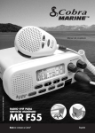
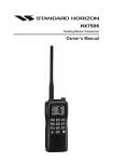
1
HX851 Floating Marine Transceiver with GPS Owner’s Manual HX851 Page 1 TABLE OF CONTENTS QUICK REFERENCE GUIDE ....................................................................................... 4 RADIO CARE ............................................................................................................... 6 RF EXPOSURE SAFETY STATEMENT .................................................................... 7 FCC NOTICE ................................................................................................................ 8 1 GENERAL INFORMATION .................................................................................. 10 2 ACCESSORIES ..................................................................................................... 10 2.1 PACKING LIST ........................................................................................... 10 2.2 OPTIONS .................................................................................................... 10 3 ABOUT THIS RADIO .......................................................................................... 11 3.1 ABOUT THE VHF MARINE BAND .......................................................... 11 3.2 EMERGENCY (CHANNEL 16 USE) ........................................................... 11 3.3 CALLING ANOTHER VESSEL (CHANNEL 16 OR 9) .............................. 12 3.4 OPERATING ON CHANNEL 13 .............................................................. 13 3.5 OPERATING ON CHANNEL 67 .............................................................. 13 3.6 VHF OPERATION ON WATER AND LAND .......................................... 13 4 GETTING STARTED ............................................................................................ 14 4.1 BATTERIES AND CHARGERS ................................................................ 14 4.2 CONNECTING A CHART PLOTTER TO THE CD-38 ......................... 18 5 CONTROLS AND CONNECTIONS .................................................................... 19 6 BASIC OPERATION ............................................................................................ 23 6.1 PROHIBITED COMMUNICATIONS .......................................................... 23 6.2 INITIAL SETUP .......................................................................................... 23 6.3 RECEPTION ............................................................................................... 23 6.4 TRANSMISSION ......................................................................................... 24 6.5 DISPLAY MODE SETUP ............................................................................ 25 6.6 USA, CANADA, AND INTERNATIONAL CHANNELS ............................. 26 6.7 SIMPLEX/DUPLEX CHANNEL USE ........................................................ 26 6.8 NOAA WEATHER CHANNELS ................................................................ 27 6.9 PRESET CHANNELS (0 ~ 9): INSTANT ACCESS .................................. 28 6.10 SCANNING ................................................................................................. 31 6.11 DUAL WATCH ............................................................................................ 33 6.12 STROBE LIGHT ......................................................................................... 34 7 DIGITAL SELECTIVE CALLING ........................................................................ 35 7.1 GENERAL ................................................................................................... 35 7.2 MARITIME MOBILE SERVICE IDENTITY (MMSI) ................................. 35 7.3 DSC DISTRESS ALERT ........................................................................... 37 7.4 ALL SHIPS CALL ...................................................................................... 41 7.5 INDIVIDUAL CALL ..................................................................................... 43 7.6 CALL WAITING DIRECTORY ................................................................... 48 7.7 GROUP CALL ............................................................................................ 50 7.8 POSITION REQUEST ............................................................................... 54 7.9 POSITION REPORT .................................................................................. 59 7.10 GEOGRAPHIC CALL .................................................................................. 62 7.11 DSC TRANSMISSION TEST .................................................................... 63 Page 2 HX851 TABLE OF CONTENTS 8 RADIO SETUP ..................................................................................................... 64 8.1 DISPLAY ...................................................................................................... 64 8.2 DIMMER ...................................................................................................... 65 8.3 CONTRAST ................................................................................................. 65 8.4 LAMP ........................................................................................................... 66 8.5 PRIORITY CHANNEL ................................................................................ 66 8.6 SCAN TYPE ............................................................................................... 67 8.7 SCAN MEMORY ........................................................................................ 67 8.8 SCAN RESUME ......................................................................................... 68 8.9 KEY BEEP .................................................................................................. 68 8.10 WEATHER ALERT ..................................................................................... 69 8.11 CHANNEL NAME ....................................................................................... 70 8.12 LED SETUP ............................................................................................... 71 9 DSC SETUP MENU ............................................................................................. 72 10 GPS SETUP ......................................................................................................... 73 10.1 UNIT POWER ............................................................................................ 73 10.2 POWER SAVE MODE .............................................................................. 74 10.3 COORDINATE SYSTEM ........................................................................... 75 10.4 PINNING ...................................................................................................... 75 10.5 TIME OFFSET ........................................................................................... 76 10.6 TIME DISPLAY ........................................................................................... 77 10.7 TIME FORMAT ........................................................................................... 77 10.8 SOG UNIT .................................................................................................. 78 10.9 POS DATA PRIORITY ............................................................................... 78 10.10 NMEA OUTPUT ......................................................................................... 79 10.11 ALTITUDE UNIT ......................................................................................... 79 11 COMPASS SETUP ............................................................................................... 80 12 WAYPOINTS .......................................................................................................... 81 12.1 MARKING A POSITION ............................................................................ 81 12.2 STORING WAYPOINTS ............................................................................ 82 12.3 EDITING A WAYPOINT ............................................................................. 83 12.4 DELETING A WAYPOINT ......................................................................... 83 12.5 SAVING A DSC POSITION CALL AS A WAYPOINT ........................... 84 12.6 NAVIGATING TO A SAVED WAYPOINT ................................................ 84 12.7 STOP NAVIGATING TO A WAYPOINT .................................................. 85 12.8 WAYPOINT SETUP ................................................................................... 85 13 MAINTENANCE .................................................................................................... 87 13.1 GENERAL ................................................................................................... 87 13.2 REPLACEMENT PARTS ........................................................................... 87 13.3 FACTORY SERVICE .................................................................................. 88 13.4 TROUBLESHOOTING CHART ................................................................. 88 14 CHANNEL ASSIGNMENTS ................................................................................. 89 15 WARRANTY .......................................................................................................... 96 16 INSTALLATION OF THE FBA-38 ....................................................................... 99 17 SPECIFICATIONS ............................................................................................... 100 17.1 GENERAL ................................................................................................. 100 17.2 TRANSMITTER ......................................................................................... 100 17.3 RECEIVER ................................................................................................ 101 17.4 GPS ........................................................................................................... 101 FCC AND CANADA RADIO LICENSE INFORMATION ...................................... 102 HX851 Page 3 QUICK REFERENCE GUIDE []/[] BUTTONS Selects the operating channel. Adjusts the audio volume level. Adjusts the squelch threshold level. Selects the item in the “DSC Call Menu” and “Setup Menu”. [DISTRESS] BUTTON Speak into the microphone in a normal voice level while pressing this switch. Note: for this button to operate a MMSI must be programmed. Lift the red cover, press the Distress button once, then press and hold until the radio alarms. [VOL(STROBE)] BUTTON [SQL] BUTTON Press this key first, then press the [ ] key to increase the audio level or press the [ ] key to reduce the audio level. Press and hold to turn on or off the LED light. Press this key first, then press the [] key to squelch or press the [] key to un-squelch the radio. TRANSMISSION SWITCH [H/L( )] BUTTON Press to toggle the transmit power between High (6W), M2 (5W), M1 (2.5W) and Low (1W). Press and hold to lock and unlock the keypad. Page 4 16/9 [16/9] BUTTON Press to recall channel 16. Press and hold to recall channel 9. [POWER] BUTTON MIC Press and hold to toggle the radio on or off. When transmitting, position your mouth about 1/2 to 1 inch (1.2 ~ 2.5 cm) away from the small mic hole. Sp e a k s l o w l y a n d clearly into the microphone. HX851 QUICK REFERENCE GUIDE [CALL(ENT)] BUTTON Press to access the “DSC MENU”. Press and hold to access the Radio and DSC setup menus. When “DSC Call Menu” or “Setup Menu” are selected, pressing this key saves a selection. [SCAN(DW)] BUTTON Press to start and stop the scanning of programmed channels. Press and hold to watch on CH16, CH70, and the current operating channel (Triple Watch). 16/9 [PRESET] BUTTON [CLR(WX)] BUTTON Press to recall the “Preset” channel. Press and hold to save the current channel into the Preset Memory. Press to cancel the menu selection. Press and hold to recall the lastused NOAA Weather Channel. HX851 Page 5 Congratulations on your purchase of the HX851! Whether this is your first portable marine VHF transceiver, or if you have other STANDARD HORIZON equipment, the STANDARD HORIZON organization is committed to ensuring your enjoyment of this high performance transceiver, which should provide you with many years of satisfying communications even in the harshest of environments. STANDARD HORIZON technical support personnel stands behind every product sold, and we invite you to contact us by phone (800) 767-2450. We appreciate your purchase of the HX851, and encourage you to read this manual thoroughly, so as to learn and fully understand the capabilities of the HX851. RADIO CARE Before using the radio: 1. It is recommended the battery be charged. Please see section “4.1.4 USING THE CD-38 CHARGER CRADLE” for details. 2. Insure the speaker microphone jack, antenna and battery are in place and firmly tightened. 3. Care must be taken if the radio was dropped and a close inspection may be needed to insure the radio case and gaskets are in adequate condition. NOTE This is to keep the rubber switches and speaker grill clean and in top operating condition after exposure to water: Clean the radio with fresh water after exposure to salt water by rinsing the radio under a sink faucet or by dunking the radio in a bucket of fresh water. After washing, use a soft cloth and thoroughly dry all parts of the radio. Page 6 HX851 RF EXPOSURE SAFETY STATEMENT SAFETY INFORMATION Your wireless handheld portable transceiver contains a low power transmitter. When the Push-to-Talk (PTT) button is pushed, the transceiver sends out radio frequency (RF) signals. In August 1996, the Federal Communications Commission adopted RF exposure guidelines with safety levels for hand-held wireless devices. This device is authorized to operate at a duty factor not to exceed 50 % (this corresponds to 50% transmission time and 50 % reception time). WARNING: To maintain compliance with the FCC’s RF exposure guidelines, this transmitter and its antenna must maintain a separation distance of at least 1 inch (2.5 centimeters) from your face. Speak in a normal voice, with the antenna pointed up and away from the face at the required separation distance. If you use a headset accessory for this radio, with the radio worn on your body, use only the Yaesu belt clip for this transceiver, and ensure that the antenna is at least 1 inch (2.5 centimeters) from your body when transmitting. Use only the supplied antenna. Unauthorized antennas, modifications, or attachments could damage the transmitter, and may violate FCC regulations. HX851 Page 7 FCC NOTICE Unauthorized changes or modifications to this equipment may void compliance with FCC Rules. Any change or modification must be approved in writing by STANDARD HORIZON, a Marine Division of YAESU USA. NOTICE This equipment has been tested and found to comply with the limits for a Class B digital device, pursuant to Part 15 of the FCC Rules. These limits are designed to provide reasonable protection against harmful interference in a residential installation. This equipment generates uses and can radiate radio frequency energy and, if not installed and used in accordance with the instructions, may cause harmful interference to radio communications. However, there is no guarantee that interference will not occur in a particular installation. If this equipment does cause harmful interference to radio or television reception, which can be determined by turning the equipment off and on, the user is encouraged to try to correct the interference by one or more of the following measures: Increase the separation between the equipment and receiver. Connect the equipment into an outlet on a circuit different from that to which the receiver is connected. Consult the dealer or an experienced marine electronics technician for help. Page 8 HX851 1 GENERAL INFORMATION The HX851 is a Submersible Floating 6-Watt portable two way marine transceiver with a 12 channel internal GPS. The transceiver has all allocated USA, International, or Canadian channels. It has emergency channel 16 which can be immediately selected from any channel by pressing the 16/9 key. NOAA (National Oceanic and Atmospheric Administration) Weather channels can also key. be accessed immediately by press and holding the The HX851 includes the following features: Memory Scanning, Priority Scanning, NOAA Weather Alert, Battery Saver, easy-to-read large LCD display, EEPROM memory back-up, Battery Life displayed on LCD, and a transmit Time-Out Timer (TOT). The HX851 transmitter provides a full 6 Watt of transmit power and is selectable to 5, 2.5, and 1 Watt to assist the user in ensuring maximum battery life. The HX851 has the capability of Digital selective Calling with Distress call including GPS position, All Ship Urgency and Safety, Individual, Group and Position Request and Position Report calls. In addition, the HX851 has navigation features which include Waypoint entering (store up to 200 waypoints), Navigation to a waypoint, Navigation to a DSC Position request, Luminescent Glow in the Dark gasket and a water enabled SOS strobe light. HX851 Page 9 2 ACCESSORIES 2.1 PACKING LIST When the package containing the transceiver is first opened, please check it for the following contents: HX851 Transceiver CAT460 Antenna FNB-121LI 7.4 V Li-ion Battery Pack CD-38 Charger Cradle for HX851 PA-48B 120VAC Wall Charger for CD-38 E-DC-19A DC Cable with 12 V Cigarette Lighter Plug for CD-38 FBA-38 Alkaline Battery Case Belt Clip Owner’s Manual 2.2 OPTIONS MH-73A4B MH-57A4B VC-24 VC-27 CN-3 CD-38 FNB-121LI FBA-38 E-DC-19A PA-48B/C/U E-DC-6 Speaker/Microphone Mini Speaker/Microphone VOX Headset Earpiece/Microphone Radio-to-Ship’s-Antenna Adapter Charger Cradle 7.4 V Li-Ion Battery Pack Alkaline Battery Case DC Cable with 12 V Cigarette Lighter Plug Wall Charger for the FNB121LI DC Cable; plug and wire only : “B” suffix is for use with 120 VAC (Type-A plug), “C” suffix is for use with 230 VAC (Type-C plug), and “U” suffix is for use with 230 VAC (Type-BF plug). Page 10 HX851 3 ABOUT THIS RADIO 3.1 ABOUT THE VHF MARINE BAND WARNING The radio frequencies used in the VHF marine band lie between 156 and 158 MHz with NOAA Weather stations available between 161 and 163 MHz. The marine VHF band provides communications over distances that are essentially “Line of sight” Actual transmission range depends much more on antenna type, gain and height than on the power output of the transmitter. The expected transmit distance a 25W Fixed Mount VHF radio can be greater than 15 miles, for a portable radio transmission the expected distance can be greater than 5 miles in “Line of sight”. The user of a Marine VHF radio is subject to severe fines if the radio is used on land. The reasoning for this is you may be near an inland waterway, or propagation anomalies may cause your transmission to be heard in a waterway. If this occurs, depending upon the marine VHF channel on which you are transmitting, you could interfere with a search and rescue case, or contribute to a collision between passing ships. For VHF Marine channel assignments refer to page 89 section 14. 3.2 EMERGENCY (CHANNEL 16 USE) Channel 16 is known as the Hail and Distress Channel. An emergency may be defined as a threat to life or property. In such instances, be sure the transceiver is on and set to CHANNEL 16. Then use the following procedure: 1. Press the PTT (Push-To-Talk) switch on the left side of the transceiver, and say “Mayday, Mayday, Mayday. This is _____, _____, _____” (your vessel’s name). 2. Then repeat once: “Mayday, _____” (your vessel’s name). 3. Now report your position in latitude/longitude, or by giving a true or magnetic bearing (state which) to a well-known landmark such as a navigation aid or geographic feature such as an island or harbor entry. 4. Explain the nature of your distress (sinking, collision, aground, fire, heart attack, life-threatening injury, etc.). 5. State the kind of assistance your desire (pumps, medical aid, etc.). 6. Report the number of persons aboard and condition of any injured. 7. Estimate the present seaworthiness and condition of your vessel. 8. Give your vessel’s description: length, design (power or sail), color and other distinguishing marks. The total transmission should not exceed one HX851 Page 11 minute. 9. End the message by saying “OVER”. Release the PTT switch and listen. 10. If there is no answer, repeat the above procedure. If there is still no response, try another channel. 3.3 CALLING ANOTHER VESSEL (CHANNEL 16 OR 9) Channel 16 may be used for initial contact (hailing) with another vessel. However, its most important use is for emergency messages. This channel must be monitored at all times except when actually using another channel. It is monitored by the U.S. and Canadian Coast Guards and by other vessels. Use of channel 16 for hailing must be limited to initial contact only. Calling should not exceed 30 seconds, but may be repeated 3 times at 2-minute intervals. In areas of heavy radio traffic, congestion on channel 16 resulting from its use as a hailing channel can be reduced significantly in U.S. waters by using Channel 9 as the initial contact (hailing) channel for non-emergency communications. Here, also, calling time should not exceed 30 seconds but may be repeated 3 times at 2-minute intervals. Prior to making contact with another vessel, refer to the channel charts in this manual, and select an appropriate channel for communications after initial contact. For example, Channels 68 and 69 of the U.S. VHF Charts are some of the channels available to non-commercial (recreational) boaters. Monitor your desired channel in advance to make sure you will not be interrupting other traffic, and then go back to either channel 16 or 9 for your initial contact. When the hailing channel (16 or 9) is clear, state the name of the other vessel you wish to call and then “this is” followed by the name of your vessel and your Station License (Call Sign). When the other vessel returns your call, immediately request another channel by saying “go to”, the number of the other channel, and “over”. Then switch to the new channel. When the new channel is not busy, call the other vessel. After a transmission, say “over”, and release the PTT (Push-To-Talk) switch. When all communication with the other vessel is completed, end the last transmission by stating your Call Sign and the word “out”. Note that it is not necessary to state your Call Sign with each transmission, only at the beginning and end of the contact. Remember to return to Channel 16 when not using another channel. Some radios automatically monitor Channel 16 even when set to other channels or when scanning. Page 12 HX851 3.4 OPERATING ON CHANNEL 13 Channel 13 is used at docks, bridges and for maneuvering in port. Messages on this channel must concern navigation only, such as meeting and passing in restricted waters. In emergencies and when approaching blind river bends, key will change the power output from High power is allowed. Pressing the Low Power (1 Watt) to Medium-1 (2.5 Watts), Medium-2 (5 Watts), or High (6 Watts) power. When you change from this channel then return to it, Low Power will be automatically selected. 3.5 OPERATING ON CHANNEL 67 When channel 67 is used for navigational bridge-to-bridge traffic between ships, High, Medium-2, or Medium-1 power may be used temporarily (in the USA band) by pressing the key. When you select this channel again, the transceiver will revert to low power. 3.6 VHF OPERATION ON WATER AND LAND This radio is capable of transmitting on Marine VHF channels. In the USA, the Federal Communications Commission (FCC) allows the use of VHF Marine band on water areas only. However the FCC does not allow the use of marine VHF channels when on land. If persons transmits on marine VHF channels on land and interferes with others communicating, the FCC could be notified, and search for the interference. Responsible parties found to be transmitting on the Marine VHF channels on land could be fined up to $10,000 for the first offense. HX851 Page 13 4 GETTING STARTED NOTE Before operating the HX851 for the first time, it is recommended that the battery be charged. Please see section “4.1.4 USING THE CD-38 CHARGER CRADLE” for details. 4.1 BATTERIES AND CHARGERS If the radio has never been used, or its charge is depleted, it may be charged by connecting the CD-38 Charger Cradle with the PA-48B battery charger, as shown in the illustration. If 12V DC power is available, the E-DC-19A DC Cable with 12 V Cigarette Lighter Plug or the optional E-DC-6 DC Cable may be used for charging the battery. The PA-48B, E-DC-19A and E-DC-6 will charge a completely discharged FNB-121LI battery pack in about 8 hours. The FNB-121LI is a high performance Li-ion battery providing high capacity in a compact package. CAUTION To avoid risk of explosion and injury, FNB-121LI battery pack should only be removed, charged or recharged in non-hazardous environments. 4.1.1 BATTERY SAFETY Battery packs for your transceiver contain Li-ion batteries. This type of battery stores a charge powerful enough to be dangerous if misused or abused, especially when removed from the transceiver. Please observe the following precautions: DO NOT SHORT BATTERY PACK TERMINALS: Shorting the terminals that power the transceiver can cause sparks, severe overheating, burns, and battery cell damage. If the short is of sufficient duration, it is possible to melt battery components. Do not place a loose battery pack on or near metal surfaces or objects such as paper clips, keys, tools, etc. When the battery pack is installed on the transceiver, the terminals that transfer current to the transceiver are not exposed. The terminals that are exposed on the battery pack when it is mounted on the transceiver are charging terminals only and do not constitute a hazard. DO NOT INCINERATE: Do not dispose of any battery in a fire or incinerator. The heat of fire may cause battery cells to explode and/or release dangerous gases. Page 14 HX851 Battery Maintenance For safe and proper battery use, please observe the following: Battery packs should be charged only in non-hazardous environments; Use only STANDARD HORIZON-approved batteries; Use only a STANDARD HORIZON, (a Marine Division of YAESU USA) approved charger. The use of any other charger may cause permanent damage to the battery. Follow charging instructions provided with the chargers. Keep the battery contacts clean. Battery Storage Store the batteries in a cool place to maximize storage life. Since batteries are subject to self-discharge, avoid high storage temperatures that cause large self-discharge rates. After extended storage, a full recharge is recommended. Battery Recycling DO NOT PLACE USED BATTERIES IN YOUR REGULAR TRASH! LI-ION BATTERIES MUST BE COLLECTED, RECYCLED OR DISPOSED OF IN AN ENVIRONMENTALLY SOUND MANNER. The incineration, land filling or mixing of Li-ion batteries with the municipal solid waste stream is PROHIBITED BY LAW in most areas. Return batteries to an approved Li-ion battery recycler. This may be where you purchased the battery. Contact your local waste management officials for other information regarding the environmentally sound collection, recycling and disposal of Li-ion batteries. HX851 Page 15 4.1.2 BATTERY INSTALLATION/REMOVAL 1. To install the battery pack, insert the battery pack into the bottom of the transceiver, then turn the Battery Pack Lock on the bottom of the transceiver to the “LOCK” position with a coin. 2. To remove the battery pack, turn the transceiver off, turn the Battery Pack Lock to the “OPEN” position with a coin, then slide out the battery from the transceiver. NOTE The battery lock must be set to “LOCK” position to ensure water integrity and from the battery coming loose. 4.1.3 BATTERY LIFE INFORMATION When the battery charge is almost depleted, a “ ” icon will appear on the display. When the “ ” icon appears, it is recommended that you charge the battery soon. NOTE When the FBA-38 Alkaline Battery Case is used, the battery icon does not display correctly. No Icon : Full Battery : Low Battery : Battery is very low : Prepare to charge the Battery Page 16 HX851 4.1.4 USING THE CD-38 CHARGER CRADLE 1. Turn the transceiver off. 2. Insert the DC plug from the PA-48B into the DC jack on the CD-38 side panel, then plug the PA-48B into the AC line outlet. 3. Insert the HX851 (with the battery pack) into the CD-38; the antenna should be at the left side when viewing the charger from the front. 4. If the HX851 is inserted correctly, the CD-38’s LED indicator will glow red. A fully-discharged pack will be charged completely in approximately 8 hours. 5. When charging is completed, the red LED indicator will change to green. PA-48B CD-38 CAUTION The CD-38 is NOT designed to be waterproof. Charge the radio in a dry location. NOTE The CD-38 is only designed for the charging of the HX851’s battery, and is not suitable for other purposes. The CD-38 may contribute noise to TV and radio reception in the immediate vicinity, so we do not recommend its use adjacent to such devices. HX851 Page 17 4.2 CONNECTING A CHART PLOTTER TO THE CD-38 The CD-38 contains three wires that are used to input or output NMEA 0183 information when the HX851 is inserted into the cradle. The HX851 outputs the following NMEA 0183 sentences at 4800 baud: GLL, GGA, GSA, GSV, RMC, DSC and DSE. The HX851 can receive and display information contained with the following NMEA 0183 sentences at 4800 baud from an external GPS or GPS Chart Plotter: GLL, GGA, and RMC. Below are the wire colors and description of the wires supplied on the CD-38. Wire Color/Description Brown - NMEA Input (+) Green - NMEA Input (–) Blue - NMEA Output (+) Connection Examples Connect to NMEA (+) output of GPS Connect to NMEA ground of GPS Connect to NMEA (+) input of GPS If you have further inquires, please feel free to contact Product Support at: Phone: (800) 767-2450 Email: [email protected] To connect a chart plotter, connect the wires between the CD-38 and the GPS and chart plotter. Insure that the wires are properly shielded from water. 16/9 Brown Connect to NMEA (+) output Green Connect to NMEA ground Blue Connect to NMEA (+) input NOTE When mounting the HX851 inside of a cabin where GPS reception is limited, the NMEA input (brown) wire may be connected to a GPS Chart Plotter to input position into the HX851. To change the HX851 from using the internal GPS antenna to an external GPS chart plotter with NMEA refer to section “10.9 POS DATA PRIORITY”. NOTE The Water Hazard LED must be turned off so the radio will output NMEA data to an external device (VHF Radio, PC, etc.). Refer to section “8.12 LED SETUP”. Page 18 HX851 5 CONTROLS AND CONNECTIONS NOTE This section defines each control of the transceiver. For detailed operating instructions, refer to section “6 BASIC OPERATION”. Refer to illustrations for the location of the following controls, switches, and connections. 16/9 NOTE When transmitting, position your mouth about 1/2 to 1 inch (1.2 ~ 2.5 cm) away from the small mic hole. Speak slowly and clearly into the microphone. ANT Jack (Top Panel) The supplied CAT460 flexible antenna is attached here. MIC/SP Jack (Top Panel) The jack accepts the optional MH-73A4B Speaker/Microphone, MH-57A4B Mini Speaker/Microphone, VC-24 VOX Headset, or VC-27 Earpiece/Microphone. When this jack is used, the internal speaker and microphone are disabled. PTT (Push-To-Talk) Switch (Left side) When pushed activates the transmitter. HX851 Page 19 DISTRESS Key (Right side) Used to send a DSC Distress Call. To send the distress call, refer to section “7.3.1 TRANSMITTING A DSC DISTRESS ALERT”. Keypad STROBE Key Press this key to activate the volume adjusting mode. Press the or key to adjust the receiver audio volume level. Secondary use: Press and hold this key to toggle the light/strobe function on and off. Key Press this key to activate the squelch adjusting mode. Press the or key to adjust the squelch threshold level. Press and hold this key for 3 seconds to open the squelch, allowing you to monitor the operating channel. Release the key to resume normal (quiet) monitoring. Key This key is used to change the operating channel, receiver volume level, and squelch threshold level. Press the key momentarily, the channel (or level) increases one step. Holding the key, the channel (or level) increases continuously. Key This key is used to change the operating channel, receiver volume level, and squelch threshold level. Press the key momentarily, the channel (or level) decreases one step. Holding the key, the channel (or level) decreases continuously. Key Press this key to toggle the transmitter output power between “High” (6 Watts), “M2” (5 Watts), “M1” (2.5 Watts), and “Low” (1 Watt) power. This key does not function on the “Transmission Inhibited” and “Low power only” channels. Secondary use: Hold down this key to lock the keypad (except the PTT, , , , and keys) so that they are not accidentally changed. The “ ” icon will appear at the bottom right corner on the display, to indicate that the functions are locked. Hold down this key until the “ ” icon disappears to unlock the radio. STROBE Page 20 HX851 Key Press this key to start scanning programmed memory channels. Secondary use: Press and hold this key to watch for a transmission on CH16, another selected channel, and CH70 until either signal is received (Triple Watch). KEY Press this key to access the DSC Call Menu. The “Individual Call”, “Group Call”, “All Ships Call”, “Position Request”, “Position Report”, “DSC Log”, and “DSC Test” functions can be accessed from the DSC Call Menu. Secondary use: Press and hold this key to access the “Radio Setup”, “DSC Setup” or “GPS Setup” menu. 16/9 Key Pressing this key immediately recalls channel 16 from any channel location. Holding down this key recalls channel 9. Pressing this key again reverts to the previous selected working channel. Key Press this key to cancel a menu selection and/or keypad entry. Secondary use: Press and hold this key to immediately recall the last-used NOAA Weather Channel from any channel location. Recalls the previouslyselected working channel when the key is pressed again. Advanced use: When the 16/9 key is held and the key is pressed, the radio will change the marine band between the USA, International, and Canadian channels. Key Press this key to recall the “Preset” channel. Secondary use: Press and hold this key to memorize the current channel as a “Preset” memory channel. When pressed a “ ” icon will be shown on the LCD display indicating the channel has been saved to preset memory. To delete the channel from preset memory, select the channel and press and hold this key until “ ” is removed from the display. (POWER) KEY Press and hold this key for two seconds to turn the radio on or off. HX851 Page 21 TX/BUSY Indicator This indicator glows green when a signal is being received and red when transmitting. When the Emergency feature is activated, this indicator blinks the internationally-recognized Morse Code “S.O.S” message. Microphone The internal microphone is located here. NOTE When transmitting, position your mouth about 1/2 to 1 inch (1.2 ~ 2.5 cm) away from the small mic hole. Speak slowly and clearly into the microphone. Speaker The internal speaker is located here. NMEA Terminals (Bottom side) Connect this NMEA input/output terminal to the GPS or Chart Plotter via the CD-38 Charger Cradle. Keep these terminals clean. Battery Pack Lock (Bottom side) Turn the Battery Pack Lock to the “OPEN” position for battery removal. BELT CLIP INSTALLATION / REMOVAL INSTALLATION Install the Belt Clip as shown below. REMOVAL The belt clip is designed to snap and lock into place. To remove the belt clip you may find it necessary to use a flat head screw driver to unlock the belt clip from the radio as shown in the image below. Page 22 HX851 6 BASIC OPERATION 6.1 PROHIBITED COMMUNICATIONS The FCC prohibits the following communications: False distress or emergency messages: Messages to “any boat” except in emergencies and radio tests; Messages to or from a vessel on land; Transmission while on land; Obscene, indecent, or profane language (potential fine of $10,000). 6.2 INITIAL SETUP 1. Install the battery pack on the transceiver (see section “4.1.2 BATTERY INSTALLATION/REMOVAL”). 2. Install the antenna onto the transceiver, hold the bottom end of the antenna, then screw it onto the mating connector on the transceiver until it is snug. Do not over-tighten. NOTE Water resistance of the transceiver is assured only when the battery pack is attached to the transceiver and MIC/SP cap is installed in the MIC/SP jack. 6.3 RECEPTION 1. Press and hold the key for two seconds to turn the transceiver on. 2. Press the key to activate the squelch adjusting mode. Press the key until the “ ” indicator appears on the display, then press the key again (or wait 3 seconds to exit from the squelch adjusting mode). 3. Press the key to activate the audio volume adjusting mode. Press the / key until the noise or audio from the speaker is at a comfortable level, then press the key again (or wait 3 seconds to exit from the volume adjusting mode). 4. Press the key to activate the squelch adjusting mode again. Press the key until the random noise disappears, then press the key again (or wait 3 seconds to exit from the squelch adjusting mode). This state is known as the “Squelch Threshold”. 5. Press the or key to select the desired channel. Refer to the channel chart on page 89 for available channels. 6. When a signal is received, adjust the volume (Press the key, followed by the / key) to desired listening level. The “ ” indicator will appear on the display indicating that the channel is being used. STROBE STROBE STROBE HX851 Page 23 NOTE When the HX851 receives and computes a fix using the internal GPS, a “ ” icon will appear on the upper right corner of the display. Position and time will appear on the lower left corner of the display. When the transceiver fails to receive a fix, the radio will show a warning in the lower left corner of the display. In this case, you may be in a poor location for satellite reception, such as indoor use; try moving to a less obstructed position. When the HX851 is first turned on, it may take several minutes to compute a fix of your position. This is normal, as the HX851 is downloading “almanac” information from the GPS satellites. 6.4 TRANSMISSION 1. Perform the “6.3 RECEPTION” instruction on the previous page. 2. Before transmitting, monitor the channel and make sure it is clear. THIS IS AN FCC REQUIREMENT! 3. For communications over short distances, press the key until “ ” is displayed on the display. This indicates Low power (approximately 1 watt). Note: Transmitting on 1 watt prolongs battery life. Low power (1 watt) should be selected whenever possible. 4. If using Low power is not effective, select M1 power (2.5 watts: “ ” icon appears), M2 power (5 watts: “ ” icon appears), or High power (6 watts: “ ” icon appears) by pressing the key. 5. When receiving a signal, wait until the incoming signal stops before transmitting. The transceiver cannot transmit and receive simultaneously. 6. Press the PTT (Push-To-Talk) switch to transmit. During transmission, the “ ” indicator will appear on the display and the TX/BUSY indicator will grow red. 7. Position your mouth about 1/2 to 1 inch (1.2 ~ 2.5 cm) away from the small mic hole. Speak slowly and clearly into the microphone. 8. When the transmission is finished, release the PTT switch. Page 24 HX851 6.4.1 TRANSMIT TIME - OUT TIMER (TOT) While the PTT switch is held down, transmission time is limited to 5 minutes. This prevents prolonged (unintentional) transmissions. About 10 seconds before automatic transmitter shutdown, a warning beep sounds from the speaker. The transceiver automatically switches to the receiving mode, even if the PTT switch is held down. Before transmitting again, the PTT switch must first be released, then pressed again after 10 seconds. This Time-Out-Timer (TOT) prevents a continuous transmission that would result from an accidentally stuck PTT switch. NOTE The PTT switch will not operate for 10 seconds after the transceiver automatically switches to the receiving mode by the TOT feature. 6.5 DISPLAY MODE SETUP The HX851 display can be setup to show Radio information with GPS icon, GPS Position, GPS Position with SOG and COG, and GPS status with the procedure below. Setup Menu 1. Press and hold the key until the “Setup Menu” appears. Radio Setup 2. Select “Radio Setup” with the / key, then press the key. Display 3. Select “Display Display” with the / key, then press the key. 4. Select the desired Display type with the / key. Radio Radio: Displays the “ ” icon only. Position Position: Displays your position and current time on the display. Navigation Navigation: Displays your position, SOG (Speed Over Ground: your current speed), COG (Course Over Ground: your current direction), and current time on the display. Compass Compass: Displays your SOG (Speed Over Ground: your current speed), COG (Course Over Ground: your current direction) by the Rose Compass. Waypoint Waypoint: Displays the distance and direction of the received vessel, and also the compass indicates the received vessel by dot (). GPS Status Status: Displays apparent reception of GPS satellites, including the bar-graph of signal strengths. 5. Press the key to store the selected setting, and return to radio operation mode. HX851 Page 25 NOTE When the “GPS Status” mode is selected in step “4” on the previous GPS Status page, the display will show the “GPS Status” page until a key is pressed. You may customize the various functions of the HX851 internal GPS unit for your operating requirements via the “GPS Setup” menu. Refer to section “10 GPS SETUP” for details. “RADIO” MODE “POSITION” MODE “NAVIGATION” MODE “WAYPOINT” MODE “GPS STATUS” MODE “COMPASS” MODE 6.6 USA, CANADIAN, AND INTERNATIONAL CHANNELS 1. To alternate from US, Canadian and International Marine Channels hold down the 16/9 key and press the key. The band will change from USA, to International, and to Canadian with each press. ” appears on the LCD for the USA band, “ ” appears for the 2. “ Canadian band, and “ ” appears for the International band. 3. Refer to the marine channel charts in section “14 CHANNEL ASSIGNMENTS” for allocated channels. “USA” BAND “CANADIAN” BAND “INTERNATIONAL” BAND 6.7 SIMPLEX/DUPLEX CHANNEL USE Refer to the VHF MARINE CHANNEL CHART (page 92) for instructions on use of simplex and duplex channels. NOTE All channels are factory-programmed in accordance with FCC (USA), Industry Canada and International regulations. The mode of operation cannot be altered from simplex to duplex or vice-versa. Simplex (ship to ship) or duplex (marine operator) mode is automatically activated, depending on the channel and whether the USA, International or Canadian operating band is selected. Page 26 HX851 6.8 NOAA WEATHER CHANNELS 1. To receive a NOAA (National Oceanic and Atmospheric Administration) weather broadcast, press and hold the key. The transceiver changes to the weather channel mode and recalls the last used NOAA weather channel. This mode consists of a preset memory bank containing the NOAA weather channels. or key to change to other weather channels. 2. Press the 3. To exit from the weather channel mode, press and hold the key. The transceiver will revert to the channel you were using prior to switching to the weather channel mode. 6.8.1 NOAA WEATHER ALERT In the event of extreme weather disturbances such as storms and hurricanes, NOAA sends a “weather alert” consisting of a 1050 Hz tone, followed by weather reports on the weather channels. When a “weather alert” is received on a weather channel, the transceiver emits a beep tone. Press the key to stop the beep tone and listen to the weather reports. NOTE By default the HX851 will alarm: a. when the radio is on a weather channel b. on the last selected Weather channel during scanning For additional settings, refer to section “8.10 WEATHER ALERT”. 6.8.2 NOAA WEATHER ALERT TESTING In the event of a major storm or other appreciable weather condition requiring vessels at sea (or other bodies of water) to be notified, the NOAA (National Oceanographic and Atmospheric Administration) broadcasts a 1050 Hz tone which the HX851 can detect and alert you of pending storm warnings (refer to section “6.8.1 NOAA WEATHER ALERT” for a discussion of how to use this feature). The 1050 Hz tone, when detected, will produce a loud beep in the speaker of the HX851, to signal that a Weather Alert Broadcast is being received. In order to test this system, NOAA broadcasts the 1050 Hz tone every Wednesday sometime between 11 AM and 1 PM local time. You may use this opportunity to test your HX851 periodically to confirm that the Weather Alert feature is working, or for training crew members on how to configure the HX851 to receive the NOAA Weather Alerts. HX851 Page 27 6.9 PRESET CHANNELS (0 ~ 9): INSTANT ACCESS 10 Preset Channels can be programmed for instant access. Each time the key is pressed the radio will step from one preset channel to another. If the key is pressed and no channels have been assigned, an alert beep will be emitted from the speaker. 6.9.1 PROGRAMMING 1. Press the / key to select a channel to be programmed. key until the preset chan2. Press and hold the nel number “ ” and a “ ” icon are displayed. key. The preset channel number 3. Release the “ ” will disappear from the display after a few second. 4. Repeat steps 2 and 3 to program the desired channels into the PRESET memory. 5. To delete a Preset Channel: press the key numerous times until the channel the preset channel you want to delete is shown on the display. Press key until “ ” icon is removed from the display. and hold the 6.9.2 OPERATION Pressing the key will toggle between Preset Chan0” through “9 9”. The Preset Channel number will disnels “0 appear after five seconds. To exit from the saved Preset Channel menu and return to the last selected “regular” channel, press the / key. 6.9.3 PRESET CHANNEL SCAN After channels have been stored into preset memory, the channels may be scanned by following the steps below: 1. To start scanning, press the 2. To stop the scan, press the Page 28 key. or key. HX851 NOTE Preset scan starts from the first to the last channel programmed into memory. When an incoming signal is detected on one of the channels during scan, the radio will pause on that channel, allowing you to listen to the incoming transmission. When the transmission stops the radio will automatically start Preset scan again. During Priority Preset scan the channels will rapidly change. 6.9.4 PRIORITY PRESET SCAN This feature enables the radio to scan preset channels while also keeping watch on a particularly important “Priority Channel”. Any channel may be programmed as a priority channel. To set the priority channel and enable Priority Scan Setup Menu 1. Press and hold the key until “Setup Menu” appears. Radio Setup 2. Press the key with “Radio Setup” selected. Priority CH Radio Setup 3. Select “Priority CH” in the “Radio Setup” menu with the / key, then press the key. 4. Press the / key to select a desired channel, then press the key. SCAN Type 5. Press the key to select “SCAN Type” and press the key. Priority Scan 6. Press the / key to select “Priority Scan”, then press the key. 7. Press the key numerous times until the setup mode is not shown. To start Preset Priority Channel scan: 1. Press the key to start, press again to stop. 2. The Priority Channel will be scanned in between each Preset channel. Example: Let us say marine channels “22A”, “68”, and “88A” are saved as preset channels. Priority scanning will proceed in the following sequence: [CH22A] [Priority Channel] [CH68] [Priority Channel] [CH88A] [Priority Channel] [CH22A] [Priority Channel] ..... 3. To stop the Preset Priority Scanning, press the or key. HX851 Page 29 NOTE When a transmission is detected on one of the preset channels, the radio will pause on that channel, and then momentarily change to the priority channel looking for an incoming signal. If the radio receives a transmission on the priority channel it will stay on the priority channel. When receiving on a non-priority channel, you will hear a break in the reception when the radio momentarily monitors the Priority Channel. When the transmission stops the radio will automatically start Priority Preset scan again. During Priority Preset scan the channels will rapidly change. Page 30 HX851 6.10 SCANNING The HX851 allows the user to select the scan type from “Memory Scan” or “Priority Scan”. The “Memory Scan” scans the preset channels and the user programmed channels. The “Priority Scan” scans the preset channels and the user programmed channels with the user selected priority channel. 6.10.1 SELECTING THE SCAN TYPE Setup Menu 1. Press and hold the key until the “Setup Menu” appears. Radio Setup / key, then press 2. Select “Radio Setup” with the the key. SCAN Type / key, then press 3. Select “SCAN Type” with the the key. Memory Scan Pri4. Select the desired Scan Type (“Memory Scan” or “Priority Scan Scan”) with the / key. 5. Press the key to store the selected setting. Radio Setup 6. Press the 16/9 key to exit the “Radio Setup” menu and return to radio operation mode. CH01A CH01A CH88A CH88A CH09 CH68A CH12 CH09 CH68A CH12 Priority Channel CH16 CH68A CH15 CH61A CH18 CH68A CH15 CH61A CH18 CH22A CH22A MEMORY SCAN PRIORITY SCAN 6.10.2 PROGRAMMING SCAN MEMORY Setup Menu 1. Press and hold the key until “Setup Menu” appears. Radio Setup 2. Press the key with “Radio Setup” selected. SCAN Memory Radio Setup 3. Select “SCAN Memory” in the “Radio Setup” menu with the / key, then press the key. 4. Press the / key to select a desired channel to be scanned, the press the key. “MEM” icon appears on the display, which indicates the channel has been selected to the scan channel. 5. Repeat step 4 for all the desired channels to be scanned. 6. To DELETE a channel from the list, select the channel then press the key. “MEM” icon disappears from the display. HX851 Page 31 7. When you have completed your selection, press the several times to return to radio operation. 16/9 key or press the 6.10.3 MEMORY SCANNING (M-SCAN) 1. Press the key to activate the squelch adjusting mode, then press the / key until the background noise disappears. 2. Press the key, the “ ” icon appears on the display. Scanning will proceed from the lowest to the highest Preset Channel and channels programmed into memory. 3. When an incoming signal is detected on one of the channels during scan, the radio will pause on that channel, allowing you to listen to the incoming transmission. The channel number will blink during reception. 4. When the transmission stops the radio will automatically start memory scan again. 5. To stop scanning, press the 16/9 or key. NOTE By default the HX851 will alarm when on a weather channel, and on the last selected Weather channel during scanning. For additional settings, refer to section “8.10 WEATHER ALERT”. 6.10.4 PRIORITY SCANNING (P-SCAN) The “Priority Scan” allows the radio to “Memory Scan” while also keeping watch on a particularly important “Priority Channel”. In the default setting, Channel 16 is set as the priority channel. You may change the priority channel to the desired channel from Channel 16 in the “Radio Setup” menu, refer to section “8.5 PRIORITY CHANNEL”. 1. Press the key to activate the squelch adjusting mode, then press the / key until the background noise disappears. 2. Press the key, the “ ” icon appears on the display. Scanning will proceed between the Preset Channel, channels programmed into memory and the priority channel. The priority channel will be scanned after each programmed channel. 3. To stop scanning, press the 16/9 or key. Page 32 HX851 NOTE When an incoming signal is detected on one of the Preset Channel or channels programmed into memory during Priority Scan, the radio will change to Dual Watch function (described in next chapter), allowing you to listen to the incoming transmission and monitoring the Priority Channel. When an incoming signal is detected on Priority Channel during Priority Scan, the radio will pause on that channel, allowing you to listen to the incoming transmission. 6.11 DUAL WATCH The Dual Watch feature allows the radio to watch the particularly important “Priority Channel”. By default the Priority channel is set to Channel 16. The priority channel can be changed, refer to section “6.10.4 PRIORITY SCANNING (P-SCAN)”. 1. Select the desired channel using the / key. 2. Press and hold the key until “ ” icon is shown on the display. Note: TW stands for Tri-Watch. It is shown to alert you that the radio is actually watching the priority channel, the working channel and CH70, the DSC channel. 3. When a transmission is received on the “Priority Channel”, the radio will stay on the Priority channel until the incoming signal disappears. 4. The Dual Watch feature will resume when the incoming signal disappears at the end of the transmission. 5. Press the key or key to stop the Dual Watch feature and return to normal operation. HX851 Page 33 6.12 STROBE LIGHT The STROBE feature utilizes the high-intensity strobe LED on the front of the HX851 as a visual distress beacon. The default setting of the Strobe is on continuously, however this may be changed so that the LED blinks the internationally-recognized Morse Code “S.O.S.” message (... --- ...) at a rate of 5 words per minute, flash rapidly (Blink1), or Flash slowly (Blink 2). NOTE To change Strobe Light operation, Refer to “8.12 LED SETUP”. 1. Hold down the key for 1 second, to active the LED. 2. The LED function is interrupted when a signal is received or if the squelch control is turned so audio is heard from the speaker. 3. To disable the LED function, hold down the key for 1 second again. STROBE STROBE Page 34 HX851 7 DIGITAL SELECTIVE CALLING 7.1 GENERAL WARNING This radio is designed to generate a digital maritime distress and safety call to facilitate search and rescue. To be effective as a safety device, this equipment must be used only within communication range of a shorebased VHF marine channel 70 distress and safety watch system. The range of signal may vary but under normal conditions should be approximately 5 nautical miles. Digital Selective Calling is a semi-automated method of establishing a radio call, it has been designated by the International Maritime Organization (IMO) as an international standard for establishing VHF, MF and HF radio calls. It has also been designated as part of the Global Maritime Distress and Safety System (GMDSS). It is planned that DSC will eventually replace aural watches on distress frequencies and will be used to announce routine and urgent maritime safety information broadcasts. This system allows mariners to instantly send a distress call with GPS position (when connected to the transceiver) to the US Coast Guard and other vessels within range of the transmission. DSC will also allow mariners to initiate or receive Distress, Urgency, Safety, Routine, Position Request, and Position Send, and Group calls to or from another vessel equipped with a DSC transceiver. 7.2 MARITIME MOBILE SERVICE IDENTITY (MMSI) 7.2.1 WHAT IS AN MMSI? An MMSI is a nine digit number used on Marine Transceivers capable of using Digital Selective Calling (DSC). This number is used like a telephone number to selectively call other vessels. THIS NUMBER MUST BE PROGRAMMED INTO THE RADIO TO OPERATE THE HX851 DSC FUNCTIONS. How can I obtain an MMSI assignment? In the USA, visit the following websites to register: http://www.boatus.com/mmsi/ or http://seatow.com/boating_safety/mmsi.asp In the Canada, visit http://www.ic.gc.ca/epic/site/smt-gst.nsf/en/sf01032e.html or http://www.usps.org/php/mmsi/rules.php HX851 Page 35 7.2.2 USER MMSI PROGRAMMING WARNING A user MMSI can be inputted only once (as per governmental regulation). Therefore please be careful not to input the incorrect MMSI number. If you need to change the MMSI after it has been programmed, the radio will have to be returned to Factory Service. Refer to the section “13.3 FACTORY SERVICE”. IMPORTANT NOTE VHF handhelds used in the United States should use the MMSI assigned to the ship to which the handheld is primarily associated, even if another radio on that ship uses the same MMSI. If you plan to use the handheld on other boats, you might want a separate MMSI number so that you can update the registration according to which boat it is currently on. 1. Press and hold down the key until the “Setup Setup Menu Menu” appears. DSC Setup 2. Press the key to select “DSC Setup” menu. 3. Press the key, then press the key to User MMSI select “User MMSI”, and press the key. / key to select the first num4. Press the ber of your MMSI, then press the key to step to the next number. 5. Repeat step 4 to set your MMSI (nine digits). 6. If a mistake was made entering, repeatedly press the key until the wrong number is selected, / key to correct entry. then press the 7. When finished programming the number, press and hold the key. 8. Enter your MMSI number again using steps 4, 5, and 6. 9. To save the MMSI into the radio, press and hold the key. 10. Press the key twice to return to radio operation. Page 36 HX851 7.3 DSC DISTRESS ALERT The HX851 is capable of transmitting and receiving DSC Distress messages to all DSC radios. The HX851 will also send the Latitude and Longitude of the vessel when the internal GPS has acquires a satellite fix. 7.3.1 TRANSMITTING A DSC DISTRESS ALERT NOTE To be able to transmit a DSC Distress Alert an MMSI number must be programmed, refer to section “7.2.2 USER MMSI PROGRAMMING”. In order for your ships location to be transmitted, the internal GPS unit must be activated, refer to “NOTE” on page 24. 1. Lift the red DISTRESS rubber cover on the right side of the transceiver and press the [DISTRESS] key. The DISTRESS ALERT “DISTRESS ALERT” menu will appear on the display. 2. Press and hold the [DISTRESS] key. The radios display will count down (3-2-1), and afterwards the HX851 will transmit the DSC Distress Alert on channel 70. The backlight of the display and keypad flashes while the radios display counts down. When the Distress signal is being sent, the TX/BUSY indicator will grow red. 3. The transceiver “shadow-watches” for a transmission between Channel 16 and Channel 70 until an acknowledgment signal is received. The display will be shown in the illustration on the right. 4. If no acknowledgment is received, the distress call is repeated in 4 minute intervals until an acknowledgment is received. 5. When a DSC Distress acknowledgment is received, a distress alarm sounds and channel 16 is automatically selected. The display shows the MMSI of the ship responding to your distress. RECEIVED ACK: acknowledgment signal is received. RECEIVED RLY: relay signal is received from another vessel or coast station. 6. To cancel the DSC distress alarm signal from the speaker, press any key. HX851 Page 37 Transmitting a DSC Distress Alert with Nature of Distress The HX851 is capable of transmitting a DSC Distress Alert with the following “Nature of Distress” categories: Undesignated, Fire, Flooding, Collision, Grounding, Capsizing, Sinking, Adrift, Abandoning, Piracy, and MOB. 1. Lift the red DISTRESS rubber cover on the right side of the transceiver and press the [DISTRESS] key. The DISTRESS ALERT “DISTRESS ALERT” menu will appear on the display. 2. Press the / key to select the desired “Nature of Distress” category. 3. When the HX851 internal GPS receiver has a fix, skip to step 4. When the HX851 internal GPS receiver is either disabled or is not receiving a fix, you may enter in your coordinates and send them manually as detailed below. a. Press the key twice. The display will be as shown in the illustration on the right. b. Enter your local time by the 24-hour system on the ]/ UTC time with the / / key. c. Enter the Latitude/Longitude of your vessel location with the / / / key. d. To store the data entered, press and hold the key. 4. Press and hold the [DISTRESS] key. The radios display will count down (3-2-1), and afterwards the HX851 will transmit the DSC Distress Alert on channel 70. The backlight of the display and keypad flashes while the radios display counts down. When the Distress signal is being sent, the TX/BUSY indicator will grow red. 5. The transceiver “shadow-watches” for a transmission between Channel 16 and Channel 70 until an acknowledgment signal is received. The display will be shown in the illustration on the right. 6. If no acknowledgment is received, the distress call is repeated in 4 minute intervals until an acknowledgment is received. 7. When a DSC Distress acknowledgment is received, a distress alarm sounds and channel 16 is automatically selected. The display shows the MMSI of the ship responding to your distress. RECEIVED ACK: acknowledgment signal is received. Page 38 HX851 RECEIVED RLY: Relay signal is received from another vessel or coast station. 8. To cancel the DSC distress alarm signal from the speaker, press any key. 7.3.2 CANCELING A DSC DISTRESS ALERT If a DSC Distress Alert was sent by error the HX851 allows you to send a message to other vessels to cancel the Distress Alert that was made in error. Press the key, then press the key. 7.3.3 RECEIVING A DSC DISTRESS ALERT 1. When a DSC Distress Alert is received, an emergency alarm sounds. Then channel 16 is automatically selected. 2. Press any key to stop the alarm. 3. Press the key several times to show information on the vessel in distress. 4. If you wish to display the position of the vessel in distress on the “WAYPOINT” screen, go to next step, otherwise press the key to return to radio operation. Waypoint Input 5. Press the key to enter the “Waypoint Input” menu, then enter the desired waypoint name (up to 11 characters), described previously (select the letter/number by pressing the / key and move the cursor by pressing the / key). 6. The ID is the MMSI from the vessel in distress. 7. When you are finished entering the waypoint name, press and hold the key several times to show the “WAYPOINT” screen. The display indicates the distance and direction of the vessel in distress, and the vessel in distress is shown on the compass display by a dot () icon. 8. To stop navigating to the location of the position request call: Setup Menu 1) Press and hold down the key until “Setup Menu” appears. Radio Setup” 2) Press the / key to select “Radio Setup”. Display 3) Press the key, then select “Display Display” with the / key. HX851 Page 39 Radio Position Navigation Com4) Press the key, and select “Radio Radio”, “Position Position”, “Navigation Navigation” or “Compass pass”, and press the key. NOTE You must continue monitoring channel 16 as a coast station may require assistance in the rescue attempt. Page 40 HX851 7.4 ALL SHIPS CALL The All Ships Call function allows contact to be established with other vessel stations without having their ID in the individual calling directory. Also, priority for the call can be designated as Urgency or Safety. URGENCY Call: This type of call is used when a vessel may not truly be in distress, but have a potential problem that may lead to a distress situation. This call is the same as saying PAN PAN PAN on channel 16. SAFETY Call: Used to transmit boating safety information to other vessels. This message usually contains information about an overdue boat, debris in the water, loss of a navigation aid or an important meteorological message. This call is the same as saying Securite, Securite, Securite. 7.4.1 SETTING UP THE ALL SHIPS RINGER The HX851 has the capability to turn off the All Ships ringer. 1. Press and hold the key until “Setup Menu” Setup Menu appears. DSC Setup 2. Press the key to select “DSC Setup” menu. DSC Beep 3. Press the key, then select “DSC Beep” with the / key. All Ships 4. Press the key, then select “All Ships” with the / key. 5. Press the key, then press the key to Off select “Off Off”. 6. Press the key to store the selected setting. Setup key twice to return to the “Setup 7. Press the Menu Menu”, then press the key again to return to radio operation. To return to enabling the ringer tone, repeat the above proOn cedure, press the key to select “On On” in step “5” above. HX851 Page 41 7.4.2 TRANSMITTING AN ALL SHIPS CALL DSC Call Menu 1. Press the key. The “DSC Menu” will appear. All Ships 2. Press the key to select “All Ships”. key. (To cancel, press the 3. Press the key.) 4. Press the / key to select the type of call Urgency Safety (“Urgency Urgency” or “Safety Safety”), then press the key. 5. Press the key again to transmit the selected type of All Ships DSC Call. 6. After the All Ships Call is transmitted, the transceiver will switch to Channel 16. 7. Listen to the channel to make sure it is not busy, then press the PTT switch and say “PAN PAN PAN” or “Securite, Securite, Securite” depending on the priority of the call. Then announce your call sign and announce the channel you wish to switch to for communications. 7.4.3 RECEIVING AN ALL SHIPS CALL 1. When an All Ships Call is received, an emergency alarm sounds. The radio will automatically change to Channel 16. The display shows the MMSI of the vessel transmitting the All Ships Call. 2. Press any key to stop the alarm. 3. Monitor channel 16 or traffic channel until the All Ship Call voice communication is completed. Page 42 HX851 7.5 INDIVIDUAL CALL This feature allows the HX851 to contact another vessel with a DSC VHF radio and automatically switch the receiving radio to a desired communications channel. This feature is similar to calling a vessel on Channel 16 and requesting to go to another channel (switching to the channel is private between the two stations). 7.5.1 SETTING UP THE INDIVIDUAL / POSITION CALL DIRECTORY The HX851 has a DSC directory that allows you to store a vessel or person’s name and the MMSI number associated with vessels to whom you wish to transmit Individual calls, Position Requests and Position Send transmissions. The HX851 can memorize up to 48 stations. To transmit an Individual call you must program this directory with information of the persons you wish to call, similar to a cellular phones telephone directory. key until “Setup Menu” 1. Press and hold the Setup Menu appears. DSC Setup 2. Press the key to select “DSC Setup” menu. Individual Direc3. Press the key, then select “Individual tory tory” with the / key. 4. Press the key. Add 5. Select “Add Add” with the / key, then press the key. 6. Press the / key to select the first letter of the name of the vessel or person you want to reference in the directory. 7. Press the key to store the first letter in the name and step to the next letter to the right. 8. Repeat step 6 and 7 until the name is complete. The name can consist of up to eleven characters, if you do not use all eleven characters press the key to move to the next space. This method can also be used to enter a blank space in the name. If a mistake was made entering in the name repeatedly press the key until the wrong character is selected, then press the / key to correct the entry. 9. After the eleventh letter or space has been entered, press and hold the key to advance to the MMSI (Maritime Mobile Service Identity Number) number entry. 10. Press the / key to scroll through numbers, 0-9. To enter the desired number and move one space to the right press the key. Repeat HX851 Page 43 11. 12. 13. 14. this procedure until all nine space of the MMSI number are entered. If a mistake was made entering in the MMSI number repeatedly pressing the key until the wrong num/ key to correct ber is selected, then press the the entry. To store the data entered, press and hold the key. To enter another individual address, repeat steps 5 through 12. Setup Menu Press the key twice to return to the “Setup Menu”, then press the key again to return to radio operation. 7.5.2 SETTING UP INDIVIDUAL REPLY Allows setting up the radio to automatically (default setting) or manually respond to a DSC Individual Call requesting you to switch to a working channel for voice communications. When “Manual” is selected the MMSI of the calling vessel is shown allowing you to see who is calling. This function is similar to caller id on a cellular phone. key until “Setup Menu” appears. 1. Press and hold the Setup Menu DSC Setup 2. Press the key to select “DSC Setup” menu. Individual Reply 3. Press the key, then select “Individual Reply” with the / key. 4. Press the key. Automatic 5. Press the / key to select “Automatic Automatic” or Manual “Manual Manual”. 6. Press the key to store the selected setting. 7. Press the key twice to return to radio operation. Page 44 HX851 7.5.3 SETTING UP INDIVIDUAL CALL RINGER When an Individual Call is received the radio will produce a ringing tone for 2 minutes. This selection allows the Individual Call ringer time to be changed. 1. Press and hold the key until “Setup Menu” Setup Menu appears. DSC Setup 2. Press the key to select “DSC Setup” menu. Individual Ringer key, then select “Individual Ringer” 3. Press the with the / key. 4. Press the key. / key to select ringing time of 5. Press the a Individual Call. 6. Press the key to store the selected setting. key twice to return to radio operation. 7. Press the The HX851 has the capability to turn off the Individual Call ringer. Setup Menu 1. Press and hold the key until “Setup Menu” appears. DSC Setup 2. Press the key to select “DSC Setup” menu. DSC Beep 3. Press the key, then select “DSC Beep” with the / key. 4. Press the key. Individual 5. Press the / key to select “Individual Individual”, then press the key. Off 6. Press the key to select “Off Off”. Setup Menu 7. Press the key twice to return to the “Setup Menu”, then press the key again to return to radio operation. To enable the ringer tone, repeat the above procedure, press the On select “On On” in step “6” above. HX851 key to Page 45 7.5.4 TRANSMITTING AN INDIVIDUAL CALL This feature allows the user to contact another vessel with a DSC radio. This feature is similar to calling a vessel on Channel 16 and requesting to go to another channel. Pre-Programmable Calling DSC Call Menu 1. Press the key. The “DSC Menu” will appear. Individual / key to select “Individual Individual”. (To 2. Press the cancel, press the key.) key. The transceiver will beep, and the 3. Press the Individual Directory “Individual Directory” will appear. 4. Press the / key to select the “Individual” you want to contact. key, then press the / key 5. Press the to select the operating channel you want to communicate on and press the key. 6. Press the key again to transmit the Individual DSC signal. 7. When an Individual Call acknowledgment is received, the HX851 automatically changes to the channel selected in step 5 and a ringing tone sounds. 8. Press the key to listen to the channel to make sure it is not busy, then key the microphone and call the other vessel you desire to communicate with. Manual Calling You may enter an MMSI number manually to contact another station without storing it in the Individual Directory. DSC Call Menu 1. Press the key. The “DSC Menu” will appear. Individual 2. Press the / key to select “Individual Individual”. (To cancel, press the key.) key. The transceiver will beep, and the 3. Press the Individual Directory “Individual Directory” will appear. Manual 4. Press the / key to select “Manual Manual”, then press the key. 5. Press the / key to scroll through numbers, 09. To enter the desired number and move one space to the right, press the key. Repeat this procedure until all nine spaces Page 46 HX851 6. 7. 8. 9. 10. 11. 12. of the MMSI number which you want to contact are entered. If a mistake was made entering in the MMSI number repeatedly press the key until the wrong number / key to correct the is selected, then press the entry. When finished entering the MMSI number, press and hold the key. The transceiver will beep, and the Select Intership CH “Select CH” menu will appear Manual Press the / key to select “Manual Manual”, then press the key. Press the / key to select the operating channel you want to communicate on and press the key. Press the key again to transmit the Individual DSC signal. When an Individual Call acknowledgment is received, the HX851 automatically changes to the channel selected in step 5 and a ringing tone sounds. Press the key to listen to the channel to make sure it is not busy, then key the microphone and call the other vessel you desire to communicate with. 7.5.5 RECEIVING AN INDIVIDUAL CALL When receiving an Individual Call, an acknowledgment transmission is sent back to the calling station to switch to a communication channel. The HX851 default setting is Automatic, but has a manual menu selection that allows you to see the vessel calling before sending an reply (refer to section “7.5.2 SETTING UP INDIVIDUAL REPLY”). This selection is useful if you want to see who is calling and requesting you to switch to a channel for communications, similar to caller ID on a cellular phone. 1. When an Individual Call is received, an Individual Call alarm sounds. The radio automatically (automatic mode selected) switches to the requested channel. The display shows the MMSI of the vessel calling. 2. Press any key to stop the alarm. 3. Press the PTT switch and talk to the calling ship. HX851 Page 47 7.6 CALL WAITING DIRECTORY The HX851 logs received Distress Calls and Individual Calls into the Call Waiting Directory for review at a later time. The DSC Call Waiting feature is similar to an answering machine where calls are recorded for review. When a call is logged while the radio is set on the DSC Standby function or when a DSC call is not replied to a “ ” icon will appear on the display. The HX851 can save the last 24 of the last received distress calls or last received 30 Individual Calls. 7.6.1 ENABLING THE CALL WAITING FEATURE Follow the steps below to enable or disable the Call Waiting feature. Setup Menu 1. Press and hold the key until “Setup Menu” appears. DSC Setup key to select “DSC Setup” menu. 2. Press the 3. Press the key, then with the / key Individual Ack select “Individual Ack”. key. 4. Press the Able to com5. Press the / key to select “Able ply Unable ply” or “Unable Unable”. key to store the selected setting. 6. Press the Setup Menu 7. Press the key twice to return to the “Setup Menu”, key once again to return to radio then press the operation. 7.6.2 REVIEWING RECEIVED CALLS LOGGED INTO THE CALL WAITING DIRECTORY DSC Call Menu 1. Press the key. The “DSC Menu” will appear. DSC Log 2. Press the / key to select “DSC Log” menu. 3. Press the key, then press the / key Distress Alert LOG to select the category (“Distress LOG” or DSC Call LOG “DSC LOG”) you want to review and/or call back. Note: When there is an unread received call, Distress Alert LOG DSC Call the category (“Distress LOG” or “DSC LOG LOG”) notation will blink. 4. Press the key, then press the / key to select the station (name or MMSI number) you want to review and/or call back. 5. Press the key, to review details for the selected station. 6. If you want to RELAY the DSC distress call to a specific ship, press the key, two times to MANUAL show the “MANUAL MANUAL” input display, then refer to setp 7. Page 48 HX851 Otherwise, press the key numerous time to exit. 7. Use the / keys to enter the first number of the MMSI, then press the key. 8. Repeat step 7 until all numbers are selected then key. press and 9. Press and hold the key to relay the Distress call to the vessel or press the to exit. 7.6.3 DELETING THE DSC LOG DSC Call Menu 1. Press the key. The “DSC Menu” will appear. DSC Log 2. Press the / key to select “DSC Log” menu. 3. Press the key, then press the / key to Log Delete select “Log Delete”. key, then press the / key 4. Press the Distress Alert LOG to select the category (“Distress LOG” or DSC Call LOG “DSC LOG”) to be deleted. 5. Press the key, then press the / key to select the station (name or MMIS number) to be deleted. 6. Press and hold the key until the station (name or MMSI number) is removed from the display. 7. Press the 16/9 key to return to radio operation. HX851 Page 49 7.7 GROUP CALL This feature allows the user to contact a group of specific vessels (example members of a yacht club) using DSC radios with Group call function to automatically switch to a desired channel for voice communications. This function is very useful for yacht clubs and vessels traveling together that want to collectively make announcements on a predetermined channel. The HX851 can memorize up to 8 group address. 7.7.1 SETUP A GROUP CALL For this function to operate the same Group MMSI must be programmed into all the DSC VHF radios within the group of vessels that will be using this feature. To understand about Group MMSI programming, first a Ship MMSI has to be understood. Ship MMSI: The first three digits called a MID (Mobile Identity Group) of a Ship MMSI denote the country the ship registered for a MMSI. The last 6 digits are specific to the Ships ID. Ship MMSI Example: If your MMSI is “366123456”, “366” is MID which denote the country and “123456” is the specific ship ID assigned to your vessel. Group MMSI: Group MMSI numbers are not assigned by the FCC or other organizations licensed to assign ship MMSI numbers. The first digit of a Group MMSI is always set to “0” by International rules. All Standard Horizon radios are preset so when programming a Group MMSI the first digit is set to “0”. The USCG recommends programming the MID of a ships MMSI into the Second, Third and Fourth digits of the Group MMSI as it denotes the area the ship is located in. The last 5 digits are decided upon by persons in the Group. This is an important step as all radios in the Group must contain the same Group MMSI so they can be contacted by each other. There is a chance that another group of vessels may program in the same Group MMSI. If this happens, simply change one or more of the last 5 digits of the Group MMSI. 1. Press and hold the key until “Setup Menu” Setup Menu appears. DSC Setup 2. Press the key to select “DSC Setup” menu. Group Directory 3. Press the key, then select “Group Directory” with the / key. 4. Press the key. Add 5. Select “Add Add” with the / key, then press the key. Page 50 HX851 6. Press the / key to scroll through the first letter of the name of the group you want to reference in the directory. 7. Press the key to store the first letter in the name. 8. Repeat step 6 and 7 until the name is complete. The name can consist of up to eleven characters, if you do not use all eleven characters press key to move to the next space. This the method can also be used to enter a blank space in the name. If a mistake was made entering in the name repeatedly press the key until the wrong character is selected, then press the / key to correct the entry. 9. After the eleventh letter or space has been entered, press and hold the key to advance to the GROUP MMSI number entry. 10. Press the / key to scroll through numbers, 09. To enter the desired number and move one space to the right press the key. Repeat this procedure until all nine space of the MMSI number are entered. 11. If a mistake was made entering in the MMSI number repeatedly press the key until the wrong number is selected, then press the / key to correct the entry. 12. To store the data entered, press and hold the key. 13. To enter another Group Address, repeat steps 5 through 12. Setup Menu 14. Press the key twice to return to the “Setup Menu”, then press the key again to return to radio operation. 7.7.2 SETTING UP THE GROUP CALL RINGER The HX851 has the capability to turn off the Group Call ringer. 1. Press and hold the key until “Setup Menu” Setup Menu appears. DSC Setup 2. Press the key to select “DSC Setup” menu. DSC Beep 3. Press the key, then select “DSC Beep” with the / key. 4. Press the key. Group 5. Press the / key to select “Group Group”, then press the key. Off 6. Press the key to select “Off Off”. Setup Menu 7. Press the key twice to return to the “Setup Menu”, then press the HX851 Page 51 key again to return to radio operation. To enable the ringer tone, repeat the above procedure, press the key to select “On” in step “6” above. 7.7.3 TRANSMITTING A GROUP CALL Pre-Programmable Calling DSC Call Menu 1. Press the key. The “DSC Menu” will appear. Group / key to select “Group Group”. (To 2. Press the cancel, press the key.) key. The transceiver will beep, 3. Press the Select Call Station and the “Select Station” directory will appear. Group 4. Press the / key to select “Group Group” you want to contact. key, then press the / key 5. Press the to select the operating channel you want to communicate on and press the key. 6. Press the key again to transmit the Group Call signal. 7. When the Group Call signal is sent, the display will be as shown in the illustration at the right. 8. After the GROUP CALL is transmitted, all the radios in the group will switch to the designated channel. 9. Listen to the channel to make sure it is not busy, then press the PTT switch and call the other vessels you desire to communicate with. Manual Calling You may enter a Group MMSI number manually to contact without Setting up a Group call number. DSC Call Menu 1. Press the key. The “DSC Menu” will appear. Group 2. Press the / key to select “Group Group”. (To cancel, press the key.) 3. Press the key. The transceiver will beep, and the Select Call Station “Select Station” directory will appear. Manual 4. Press the / key to select “Manual Manual”, then press the Page 52 key. HX851 5. Press the / key to scroll through numbers, 0-9. To enter the desired number and move one space to the right press the key. Repeat this procedure until all nine space of the MMSI number which you want to contact are entered. If a mistake was made entering in the MMSI numkey until the wrong ber repeatedly press the number is selected, then press the / key to correct the entry. 6. When finished entering the MMSI number, press and hold the key. The transceiver will beep, Select CH and the “Select CH” menu will appear 7. Press the / key to select the operating channel you want to communicate on and press the key. 8. Press the key again to transmit the Group Call signal. 9. When the Group Call signal is sent, the display will be as shown in the illustration at the right. 10. After the Group Call is transmitted, all the radios in the group will switch to the designated channel. 11. Listen to the channel to make sure it is not busy, then press the PTT switch and call the other vessels you desire to communicate with. 7.7.4 RECEIVING A GROUP CALL 1. When a Group Call is received, the HX851 will produce a ringing alarm sound and the display shows the Group name or Group MMSI. 2. Press any key to stop the alarm. 3. Press the key to switch the radio to the requested channel. 4. Monitor the channel for the person calling the Group for a message. 5. If you want to respond, monitor the channel to make sure it is clear, then press the PTT switch and talk to the calling ship(s). NOTE After a Group Call is received, the time the call was made and the ships MMSI or vessels name will appear on the display. HX851 Page 53 7.8 POSITION REQUEST Advancements in DSC have made it possible to poll the location of another vessel and show the position of that vessel on the display of the HX851. Standard Horizon has taken this feature one step. After receiving a position from another vessel, the HX851 can navigate to the location of the polled vessel. This is a great feature for a person on a small craft wanting to get back to the main ship or to navigate to a location of your buddy in a kayak. If any Standard Horizon GPS chart plotter is connected to the HX851 through the CD-38, the polled position of the vessel is shown on the display of the GPS chart plotter making it easy to navigate to the location of the polled vessel. This is a great feature for anyone wanting to know the position of another vessel. For example your buddy that is catching fish, or finding the location of a person you are cruising with. NOTE The other vessel must have an operating GPS receiver connected to its DSC transceiver and must not have its transceiver set to deny position requests. (Refer the section “7.5 INDIVIDUAL CALL” to enter information into the Individual Directory). 7.8.1 SETTING UP POSITION REPLY The HX851 can be set up to “automatically” or “manually” send your position to another vessel. This selection is important if you are concerned about someone polling the position of your vessel that you may not want to. In the “Manual” mode you will see the MMSI or persons name shown on the display allowing you to choose to send your position to the requesting vessel. 1. Press and hold the key until “Setup Menu” Setup Menu appears. DSC Setup 2. Press the key to select “DSC Setup” menu. Position Reply 3. Press the key, then select “Position Reply” with the / key. 4. Press the key. Automatic 5. Press the / key to select “Automatic Automatic” or Manual Automatic “Manual Manual”. In “Automatic Automatic” mode, after a DSC POS Request is received, the radio will automatically transmit Manual your vessels position. In “Manual Manual” mode, the display of the HX851 will show who is requesting the position. 6. Press the key to store the selected setting. 7. Press the key twice to return to radio operation. Page 54 HX851 7.8.2 SETTING UP THE POSITION REQUEST RINGER The HX851 has the capability to turn off the Position Request ringer. 1. Press and hold the key until “Setup Menu” Setup Menu appears. DSC Setup 2. Press the key to select “DSC Setup” menu. DSC Beep 3. Press the key, then select “DSC Beep” with / key. the 4. Press the key. Position Re5. Press the / key to select “Position quest key. quest”, then press the Off 6. Press the key to select “Off Off”. Setup 7. Press the key twice to return to the “Setup Menu key again to return to Menu”, then press the radio operation. To enable the ringer tone, repeat the above procedure, On press the key to select “On On” in step “6” above. 7.8.3 TRANSMITTING A POSITION REQUEST TO ANOTHER VESSEL Pre-Programmable Request DSC Call Menu 1. Press the key. The “DSC Menu” will appear in the display. Pos Re2. Press the / key to select the “Pos quest quest”. 3. Press key. The names shown have been previously saved in the Individual directory. 4. Press the / key to select a name, then press the key. 5. Press the key again to transmit the Position Request DSC call. 6. When the HX851 receives the position from the polled vessel, a ringing alarm will sound, and the display shows the position of the vessel and also transferred to a GPS Chart plotter if connected. 7. Press any key to stop the alarm. 8. If you wish to display the position of the polled vessel on the “WAYPOINT” screen, go to next step, otherwise press the key to return to radio operation. Waypoint Input 9. Press the key to enter the “Waypoint Input” menu. 10. Press and hold the key several times until the display changes to the HX851 Page 55 “WAYPOINT” Screen. The display indicates the distance and direction of the polled vessel, and also the compass indicates the polled vessel as a dot (). 11. To stop navigating to the location of the position request call: Setup Menu key until “Setup Menu” 1) Press and hold down the appears. Radio Setup” 2) Press the / key to select “Radio Setup”. Display 3) Press the key, then select “Display Display” with the / key. Radio Position Navigation Com4) Press the key, and select “Radio Radio”, “Position Position”, “Navigation Navigation” or “Compass pass” with the / key, and press the key. NOTE If the HX851 does not receive position data from the polled vessel, the NO POSITION DATA display will show “NO DATA”. Manual Request You may enter an MMSI number manually to contact without Setting up the Individual / Position Call Directory. DSC Call Menu 1. Press the key. The “DSC Menu” will appear in the display. Pos Request 2. Press the / key to select the “Pos Request”. 3. Press key. Manual 4. Press the / key to select “Manual Manual”, then press the key. 5. Press the / key to scroll through numbers, 09. To enter the desired number and move one space to the right press the key. Repeat this procedure until all nine spaces of the MMSI number which you want to contact are entered. If a mistake was made entering in the MMSI number repeatedly press the key until the wrong number is selected, then press the / key to correct the entry. 6. When finished entering the MMSI number, press and hold the key. 7. Press the key to transmit the position request DSC call. 8. When the HX851 receives the position from the polled vessel, a ringing alarm will sound, and the display shows the position of the vessel and also transferred to the GPS Chart plotter if connected to the Page 56 HX851 9. 10. 11. 12. 13. 14. CD-38, refer to section “4.2 CONNECTING A CHART PLOTTER TO THE CD-38”. Press any key to stop the alarm. If you wish to display the position of the polled vessel on the “WAYPOINT” screen, go to next step, otherkey to return to radio operation. wise press the Waypoint Input Press the key to enter the “Waypoint Input” menu. Then enter the desired waypoint name (up to 11 characters), described previously (select the letter/number by pressing the / key and move the cursor by pressing the / key). The ID is the MMSI from the polled vessel. When you are finished entering the waypoint name, press and hold the key several times until the “WAYPOINT” screen appears. The display indicates the distance and direction of the polled vessel, and also the compass indicates the polled vessel as a dot (). To stop navigating to the location of the position request call: Setup Menu 1) Press and hold down the key until “Setup Menu” appears. Radio Setup” 2) Press the / key to select “Radio Setup”. Display 3) Press the key, then select “Display Display” with the / key. Radio Position 4) Press the key, and select “Radio Radio”, “Position Position”, Navigation Compass Compass” with the “Navigation Navigation”or “Compass / key, and press the key. HX851 Page 57 7.8.4 RECEIVING A POSITION REQUEST When a Position Request Call is received from another vessel a ringing alarm will sound. Operation and transceiver function differs depending on “Position Reply” menu in the “DSC Setup” menu setting. Refer to section “7.8.1 SETTING UP POSITION REPLY”. Automatically reply: 1. When a Position Request Call is received, a calling alarm sounds 5 times. Then requested position coordinates are transmitted automatically to the vessel requesting your vessels position. 2. To exit from Position Request display, press the key. Manually reply: 1. When a Position Request Call is received from another vessel, the display will be as shown in the illustration at the right and a ringing alarm will sound. 2. Press any key to stop the alarm. 3. To send your vessels position to the requesting vessel, press the Or to exit from position request display, press the key. Page 58 key. HX851 7.9 POSITION REPORT The feature is similar to Position Request, however instead of requesting a position of another vessel this function allows you to send your position to another vessel. NOTE To transmit a Position Send Call, you must setup the HX851 DSC Individual / Position Call Directory with the name of the vessel(s) or person and the MMSI of the DSC radio you wish to send your position to. To setup this directory refer to section “7.5.1 SETTING UP THE INDIVIDUAL / POSITION CALL DIRECTORY”. 7.9.1 SETTING UP A POSITION REPORT RINGER The HX851 has the capability to turn off the Position Report ringer. Setup Menu 1. Press and hold the key until “Setup Menu” appears. DSC Setup 2. Press the key to select “DSC Setup” menu. DSC Beep 3. Press the key, then select “DSC Beep” with the / key. Position Report 4. Press the key, then select “Position Report” with the / key. 5. Press the key, then press the key to Off select “Off Off”. 6. Press the key to store the selected setting. Setup 7. Press the key twice to return to the “Setup Menu Menu”, then press the key again to return to radio operation. To return to enabling the ringer tone, repeat the above proOn cedure, press the key to select “On On” in step “5” above. 7.9.2 TRANSMITTING A DSC POSITION REPORT CALL Pre-Programmable Calling DSC Call Menu 1. Press the key. The “DSC Menu” will appear in the display. Pos Re2. Press the / key to select the “Pos port port”. 3. Press key. 4. Press the / key to select a name in the directory, then press the key. 5. Press the key again to send your position to the selected vessel. HX851 Page 59 6. Press the key to return to radio operation. Manual Calling You may enter an MMSI number manually to contact another vessel without setting up the Individual / Position Call Directory. DSC Call Menu 1. Press the key. The “DSC Menu” will appear in the display. Pos Re2. Press the / key to select the “Pos port port”. 3. Press key. Manual 4. Press the / key to select “Manual Manual”, then press the key. 5. Press the / key to scroll through numbers, 0-9. To enter the desired number and move one space to the right press the key. 6. Repeat this procedure until all nine spaces of the MMSI number which you want to contact are entered. If a mistake was made entering in the MMSI number repeatedly press the key until the wrong number is selected, then press the / key to correct the entry. 7. When finished entering the MMSI number, press and hold the key. 8. Press the key again to send your position to the selected vessel. 9. Press the key to return to radio operation. Page 60 HX851 7.9.3 RECEIVING A DSC POSITION REPORT CALL When another vessel transmits their vessels location to the HX851 the following will happen: 1. When a Position Report Call is received, a calling alarm sounds 5 times and NMEA DSC and DSE sentences are outputted on the CD-38 charging cradle wires. 2. The display shows the position from the vessel sending it’s position. 3. If you wish to display the position of the received vessel on the “WAYPOINT” screen, go to next the step, otherwise press the key to return to radio operation. Waypoint Input 4. Press the key to enter the “Waypoint Input” menu, then enter the desired waypoint name (up to 11 characters), described previously (select the letter/number by pressing the / key and move the cursor by pressing the / key). 5. The ID is the MMSI from the received vessel. 6. When you are finished entering the waypoint name, press and hold the key several times until the “WAYPOINT” display is shown. The display indicates the distance and direction of the received vessel, and also the compass indicates the received vessel as a dot (). 7. To stop navigating to the location of the position request call: Setup Menu 1) Press and hold down the key until “Setup Menu” appears. Radio Setup” 2) Press the / key to select “Radio Setup”. Display 3) Press the key, then select “Display Display” with the / key. Radio Position Navigation 4) Press the key, and select “Radio Radio”, “Position Position”, or “Navigation Navigation” with the / key, and press the key. HX851 Page 61 7.10 GEOGRAPHIC CALL The HX851 can receive Geographic Calls from another station. 1. When a Geographic Call is received, a ringing sound will be produced and the display shows the MMSI” (or name) of the station transmitting the Geographic Call. 2. Press any key to stop the alarm. key to switch the radio to the requested channel. 3. Press the 4. Press the PTT on the mic and talk to the calling station. 7.10.1 SETTING UP THE POSITION GEOGRAPHIC RINGER The HX851 has the capability to turn off the Geographic ringer. Setup Menu 1. Press and hold the key until “Setup Menu” appears. DSC Setup 2. Press the key to select “DSC Setup” menu. DSC Beep 3. Press the key, then select “DSC Beep” with the / key. 4. Press the key. Geographic 5. Press the / key to select “Geographic Geographic”, then press the key. Off 6. Press the key to select “Off Off”. Setup 7. Press the key twice to return to the “Setup Menu Menu”, then press the key again to return to radio operation. To enable the ringer tone, repeat the above procedure, On press the key to select “On On” in step “6” above. Page 62 HX851 7.11 DSC TRANSMISSION TEST Use the following procedure to ensure the DSC feature is functioning with another DSC radio. NOTE The radio will not transmit a DSC test call until a MMSI is programmed. Refer to section “7.2 MARITIME MOBILE SERVICE IDENTITY (MMSI)”. DSC Call Menu key. The “DSC Menu” will ap1. Press the pear in the display. DSC Test 2. Press the / keys to select the “DSC Test”, then press the key. 3. Choose a or b below: a. Select MMSI from Individual directory: Select the station (name or MMSI number) using the / keys that the DSC test signal will be transmitted to, then press the key. Go to step 4. b. Manually enter MMSI of know vessel or station: Manual Select “Manual Manual” using the / keys, then press the key and enter the MMSI number (nine digits) whom you want to send the test signal. To do this, press the / keys to scroll through numbers “0-9,” then press the key to move the entry location to the right. If a mistake was made entering in the MMSI number, repeatedly pressing the key until the wrong number is selected, then press the / keys to correct the entry. When finished entering the MMSI number, press and hold the key. 4. Press the key again to transmit the Test signal. 5. If the vessel you called does not transmit an Wait acknowledgement message the HX851 will show “Wait for acknowledge acknowledge”. 6. When the ship you called does transmit an acknowledgement call, the radio will ring. 7. Press the key to stop the ringing, and press again to exit to normal radio mode. HX851 Page 63 8 RADIO SETUP The HX851’s “Radio Setup” mode allows a number of the HX851 operating Radio Setup parameters to be custom-configured for your operating requirements. 8.1 DISPLAY Allows setting up the HX851 display mode. The default setting is “Position”. Setup Menu 1. Press and hold the key until “Setup Menu” appears. Display Radio 2. Press the key, then select “Display Display” in the “Radio Setup Setup” menu with the / key. 3. Press the key. 4. Press the / key to select the desired mode. Radio Radio: Displays the “ ” icon only. Position Position: Displays your position and current time on the display. Navigation Navigation: Displays your position, SOG (Speed Over Ground: your current speed), COG (Course Over Ground: your current direction), and current time on the display. Compass Compass: Displays your SOG (Speed Over Ground: your current speed), COG (Course Over Ground: your current direction) by the Rose Compass. Waypoint Waypoint: Displays the distance and direction of the received vessel, and also the compass indicates the received vessel as a dot (). GPS Status Status: Displays apparent reception of GPS satellites, including the bar-graph of signal strengths. 5. Press the key to store the selected display. NOTE When the “GPS Status” mode is selected in step “4” above, the display GPS Status will show the “GPS Status” page until any key is pressed. “RADIO” MODE Page 64 “POSITION” MODE “NAVIGATION” MODE “WAYPOINT” MODE “GPS STATUS” MODE “COMPASS” MODE HX851 8.2 DIMMER Allows setting up the display/keypad backlight intensity or to turn it off. The default setting is “High”. 1. Press and hold the key until “Setup Menu” appears. Setup Menu Dimmer Radio key, then select “Dimmer Dimmer” in the “Radio 2. Press the Setup Setup” menu with the / key. 3. Press the key. / key to select the desired level. 4. Press the 1/2 2/3 3/4 4/5 5/6 6/High High The dimmer level can be set to “1 High” or Off Off “Off Off”. When “Off Off” is selected, the lamp is extinguished. 5. Press the key to store the selected level. 6. To exit this menu and return to radio operation mode press the 16/9 key or press the key several times. 8.3 CONTRAST The contrast may be changed for best viewing in sunlight, dusk or night allowing for best readability. The default setting is “9”. 1. Press and hold the key until “Setup Menu” appears. Setup Menu Contrast Radio 2. Press the key, then select “Contrast Contrast” in the “Radio Setup Setup” menu with the / key. 3. Press the key. 4. Press the / key to select the desired level. 0” to “20 20 The contrast level can be set from “0 20”. 5. Press the key to store the selected level. 6. To exit this menu and return to radio operation mode press the 16/9 key or press the key several times. HX851 Page 65 8.4 LAMP This menu selection is used to setup the illumination time of the display and keypad. The default setting is “5 Seconds”. Setup Menu 1. Press and hold the key until “Setup Menu” appears. Lamp Radio key, then select “Lamp Lamp” in the “Radio 2. Press the Setup Setup” menu with the / key. 3. Press the key. / key to select the desired time. 4. Press the Continuous Continuous: Illuminates the display/keypad continuously. 1/2 2/3 3/4 4/5 5/6 6/8 8/10 10 12 15 20 25 30 Seconds 10/12 12/15 15/20 20/25 25/30 Seconds: Illuminates the display/keypad for the selected time when press any key (except the PTT switch). Off Off: Disables the display/keypad lamp illumination. key to store the selected setting. 5. Press the 6. To exit this menu and return to radio operation mode press the press the key several times. 16/9 key or 8.5 PRIORITY CHANNEL Allows selection of the priority channel when priority scan is enabled. The default setting is “Channel 16”. Setup Menu 1. Press and hold the key until “Setup Menu” appears. Priority CH Ra2. Press the key, then select “Priority CH” in the “Radio Setup Setup” menu with the / key. 3. Press the key. 4. Press the / key to select the desired channel to be a priority. 5. Press the key to store the selected setting. 6. To exit this menu and return to radio operation mode press the 16/9 key or press the key several times. Page 66 HX851 8.6 SCAN TYPE This selection is used to select the scan mode between “Memory Scan” and “Priority Scan.” The default setting is “Priority SCAN”. 1. Press and hold the key until “Setup Menu” appears. Setup Menu SCAN Type Rakey, then select “SCAN Type” in the “Ra2. Press the dio Setup Setup” menu with the / key. 3. Press the key. Priority SCAN / key to select “Priority SCAN” or 4. Press the Memory SCAN “Memory SCAN”. 5. Press the key to store the selected setting. 6. To exit this menu and return to radio operation mode key several times. press the 16/9 key or press the 8.7 SCAN MEMORY To be able to scan channels the radio must be programmed. This section allows channels to be stored in scan memory. Setup Menu 1. Press and hold the key until “Setup Menu” appears. SCAN Memory 2. Press the key, then select “SCAN Memory” in the Radio Setup “Radio Setup” menu with the / key. 3. Press the key. 4. Press the / key to select a desired channel to be scanned, the press the key. “MEM” icon appears on the display, which indicates the channel has been selected to the scan channel. 5. Repeat step 4 for all the desired channels to be scanned. 6. To DELETE a channel from the list, select the channel then press the key. “MEM” icon disappears from the display. 7. When you have completed your selection, press the 16/9 key or press the several times to return to radio operation. HX851 Page 67 8.8 SCAN RESUME This selection is used to select the time which the HX851 waits after a transmission ends before scanning is started. The default setting is “2sec”. Setup Menu 1. Press and hold the key until “Setup Menu” appears. SCAN Resume key, then select “SCAN Resume” in the 2. Press the Radio Setup “Radio Setup” menu with the / key. 3. Press the key. / key to select the desired resume 4. Press the 1/2 2/3 3/4 4/5 5 sec time. The resume time can be set to “1 sec” or Off Off “Off Off”. In the “Off Off” selection, the scanner will resume after the other station stops transmitting (carrier drops). 5. Press the key to store the selected setting. 6. To exit this menu and return to radio operation mode press the 16/9 key or press the key several times. 8.9 KEY BEEP This selection controls the loudness of the key beep or turns it off. The default setting is “Level 5”. 1. Press and hold the key until “Setup Menu” appears. Setup Menu Key Beep Radio 2. Press the key, then select “Key Beep” in the “Radio Setup Setup” menu with the / key. 3. Press the key. 4. Press the / key to select the desired beep Level 1 Level 2 level. The beep level can be set to “Level 1”, “Level 2”, Level 3 Level 4 Level 5 Level 6 High Off “Level 3”, “Level 4”, “Level 5”, “Level 6”, “High High”, or “Off Off”. key to store the selected setting. 5. Press the 6. To exit this menu and return to radio operation mode press the 16/9 key or press the key several times. Page 68 HX851 8.10 WEATHER ALERT This selection allows the NOAA Weather Alert to be setup. The default setting is “ON SCAN and WX CH”. Setup Menu 1. Press and hold the key until “Setup Menu” appears. Weather Alert key, then select “Weather Alert” in the 2. Press the Radio Setup “Radio Setup” menu with the / key. 3. Press the key. / key to select the desired Weather 4. Press the Alert mode. ON WX CH CH: Emits a loud beep when the Weather Alert is received while receiving the Weather channel. ON SCAN SCAN: This menu selection, automatically scans the last selected weather channel and produces and alert. ON SCAN and WX CH CH: This menu selection, produces an alert during scanning when NOAA broadcasts an alert on the last selected weather channel and when monitoring a Weather channel. Off Off: Disable the Weather Alert function. 5. Press the key to store the selected setting. 6. To exit this menu and return to radio operation mode press the 16/9 key or press the key several times. HX851 Page 69 8.11 CHANNEL NAME This selection allows you to customize the name of a channel from the default name. Example: CH69 PLEASURE to HOOKUP Setup Menu 1. Press and hold the key until “Setup Menu” appears. CH Name Radio 2. Press the key, then select “CH Name” in the “Radio Setup Setup” menu with the / key. ] key. 3. Press the 4. Press the / key to select the channel to be 69 USA named (In this case, select to “69 USA”) and press the key. 5. Press the / key to scroll through the alphabet and 0 - 9. Enter the first letter of channel name. 6. Press the key to enter the desired letter and move the cursor one space to the right. 7. Repeat the procedure until the name is complete. The name can consist of up to 11 characters. If you do not use all 11 characters, press the key to move to the next space. This method can also be used to enter a blank space in the name. To clear the previous letter, press the key. 8. If a mistake was made entering repeatedly press the 16/9 key until the wrong character is selected, then press the / key to correct the entry. 9. Press and hold down the key to enter the name. 10. If you want to enter the name of another channel, repeat steps 4 through 9. 11. To exit this menu and return to radio operation mode press the press the key several times. Page 70 16/9 key or HX851 8.12 LED SETUP Allows setting up the TX/BUSY LED mode. The default setting is “Continuous”. 1. Press and hold the key until “Setup Menu” appears. Setup Menu LED Setup Radio key, then select “LED Setup” in the “Radio 2. Press the Setup Setup” menu with the / key. 3. Press the key. / key to select the LED to be 4. Press the changed and press the key. Transmit Transmit: LED is illuminated when PTT button is pressed. Default is On. Receive Receive: LED is illuminated when a signal is being received. Default is On. Emergency Emergency: Controls the LED, when the key is pressed. Default is Continuous. Water Hazard LED LED: Default is On. On Off 5. Press the / key to select “On On” or “Off Off” for the Continuous SOS Transmit LED, Receive LED and Water Hazard LED, or “Continuous Continuous”, “SOS SOS”, Blink1 Blink2 “Blink1 Blink1”, or “Blink2 Blink2” for the Emergency LED. Continuous Continuous: The LED glows continuously in white when the Emergency function is engaged SOS SOS: The LED flashes according to the “S.O.S” Morse Code (. . . - - - . . .) when the Emergency function is engaged. This is the default setting. Blink1 Blink1: The LED flashes rapidly when the Emergency function is engaged. Blink2 Blink2: The LED flashes slowly when the Emergency function is engaged. 6. Press the key to store the selected setting. 7. To exit this menu and return to radio operation mode press the 16/9 key or press the key several times. STROBE WATER STROBE NOTE When the HX851 is immersed in water the SOS strobe light will start blinking. This allows you to be able to see the radio that may have fallen overboard at night or when worn on a life vest aid in rescuing a person in the water. HX851 Page 71 9 DSC SETUP MENU The HX851’s DSC Setup mode allows a number of the HX851 DSC parameters to be custom-configured for your operating requirement. INDIVIDUAL DIRECTORY - Refer to section 7.5.1 INDIVIDUAL REPLY - Refer to section 7.5.2 INDIVIDUAL ACK - Refer to section 7.6.1 INDIVIDUAL RINGER - Refer to section 7.5.3 GROUP DIRECTORY - Refer to section 7.7.1 POSITION REPLY - Refer to section 7.8.1 DSC BEEP - Individual - Refer to section 7.5.3 - Group - Refer to section 7.7.2 - All Ships - Refer to section 7.4.1 - Position Request - Refer to section 7.8.2 - Position Report - Refer to section 7.9.1 - Geographic - Refer to section 7.10.1 DSC Scan When the radio is shipped from the factory it is programmed so CH70 (the DSC channel) is scanned at all times. This menu selection allows you to disable the DSC SCAN. However, turning off DSC SCAN will disable the radio from receiving DSC calls, (Individual Call, All Ships Call, Distress Call and Position Requests. If you want to use any of the functions the selection should be left ON. Setup 1. Press and hold the key until “Setup Menu Menu” appears. DSC Setup 2. Press the key to select “DSC Setup” and key. press the DSC Scan 3. Press the key to select “DSC Scan” and press the key. Off 4. Press the or key to select “Off Off” and press the key. 5. Press the 16/9 key to exit. USER MMSI - Refer to section 7.2.2 Page 72 HX851 10 GPS SETUP GPS Setup The HX851’s “GPS Setup” mode allows a number of the HX851 internal GPS unit’s parameters to be custom-configured for your operating requirements. 10.1 UNIT POWER This selection allows the internal GPS unit to be turned on or off to conserve battery power. The default setting is “On”. 1. Press and hold the key until “Setup Menu” Setup Menu appears. GPS Setup key to select “GPS Setup” menu. 2. Press the Unit Power 3. Press the key, then select “Unit Power” in GPS Setup / key. the “GPS Setup” menu with the 4. Press the key. On Off 5. Press the / key to select “On On” or “Off Off”. key to store the selected level. 6. Press the 7. To exit this menu and return to radio operation mode press the 16/9 key or press the key several times. HX851 Page 73 10.2 POWER SAVE MODE This menu item selects the Battery Save Mode for the internal GPS unit. The default setting for the Power Save Mode is “Level 1”. 1. Press and hold the key until “Setup Menu” Setup Menu appears. GPS Setup key to select “GPS Setup” menu. 2. Press the Power Save Mode 3. Press the key, then select “Power Mode” GPS Setup / key. in the “GPS Setup” menu with the 4. Press the key. 5. Press the / key to select the desired level. Off Off: GPS Signals are always being received. Level 1 1: Activates the GPS receiver for 0.4 seconds every 5 seconds. Level 2 2: Activates the GPS receiver for 50 seconds every 1 minute. Level 3 3: Activates the GPS receiver for 50 seconds every 3 minutes. Level 4 4: Activates the GPS receiver for 50 seconds every 5 minutes. 6. Press the key to store the selected level. 7. To exit this menu and return to radio operation mode press the 16/9 key or press the key several times. NOTE When Navigation or the GPS Status page is selected in the Radio Setup menu (refer to section “8.1 DISPLAY”), the GPS receiver will be automatically set to Level 1. Page 74 HX851 10.3 COORDINATE SYSTEM This menu item selects the Coordinate System to be shown on the HX851 display. The default setting is “ddd mm.mmm”. 1. Press and hold the key until “Setup Menu” Setup Menu appears. GPS Setup key to select “GPS Setup” menu. 2. Press the Coordinate Sys3. Press the key, then select “Coordinate tem GPS Setup / key. tem” in the “GPS Setup” menu with the 4. Press the key. 5. Press the / key to select the desired Coordinate System. The Coordinate System can ddd mm ss ddd mm.mm ddd be select to “ddd ss”, “ddd mm.mm”, or “ddd mm.mmm mm.mmm”. key to store the selected system. 6. Press the 7. To exit this menu and return to radio operation mode press the 16/9 key or press the key several times. 10.4 PINNING This selection selects whether the updating of your current position enables or disables when your vessel stops. The default setting is “On”. 1. Press and hold the key until “Setup Menu” Setup Menu appears. GPS Setup 2. Press the key to select “GPS Setup” menu. Pinning 3. Press the key, then select “Pinning Pinning” in the GPS Setup / key. “GPS Setup” menu with the 4. Press the key. On Off 5. Press the / key to select “On On” or “Off Off”. On On: When pinning is turned “on”, the HX851 will not update its position unless the vessel travels over 10Ft. Off Off: When the vessel is underway or stopped, the HX851 continuously updates its position (unless transmitting). This improves accuracy of the position fix. 6. Press the key to store the selected setting. 7. To exit this menu and return to radio operation mode press the press the key several times. HX851 16/9 key or Page 75 10.5 TIME OFFSET The HX851 uses the time received from the GPS satellites. The time received is in UTC. This selection is used to enter an offset between your local time and UTC time. 1. Press and hold the key until “Setup Menu” Setup Menu appears. GPS Setup 2. Press the key to select “GPS Setup” menu. Time Offset key, then select “Time Offset” in 3. Press the GPS Setup the “GPS Setup” menu with the / key. 4. Press the key. / key to select time offset 5. Press the from UTC. See illustration below to find your off00:00 set time from UTC. If “00:00 00:00” is assigned, the time is the same as UTC (Universal Time Coordinated or GMT Greenwich Mean Time). 6. Press the key to store the time offset. 7. To exit this menu and return to radio operation mode key several times. press the 16/9 key or press the OFFSET TIME TABLE Page 76 HX851 10.6 TIME DISPLAY Allows the time shown on the display to be shown in local (with offset inputted in section “9.4 TIME OFFSET”) or UTC time. The default setting is “UTC”. 1. Press and hold the key until “Setup Menu” Setup Menu appears. GPS Setup key to select “GPS Setup” menu. 2. Press the Time Display 3. Press the key, then select “Time Display” in GPS Setup / key. the “GPS Setup” menu with the 4. Press the key. UTC Lo5. Press the / key to select “UTC UTC” or “Local cal”. key to store the selected setting. 6. Press the 7. To exit this menu and return to radio operation mode press the 16/9 key or press the key several times. 10.7 TIME FORMAT Allows the time shown on the display to be shown in 12 hours or 24 hours time formats. The default setting is “12 hours”. 1. Press and hold the key until “Setup Menu” Setup Menu appears. GPS Setup 2. Press the key to select “GPS Setup” menu. Time Format 3. Press the key, then select “Time Format” in GPS Setup / key. the “GPS Setup” menu with the 4. Press the key. 24H 12H 5. Press the / key to select “24H 24H” or “12H 12H”. key to store the selected setting. 6. Press the 7. To exit this menu and return to radio operation mode press the 16/9 key or press the key several times. HX851 Page 77 10.8 SOG UNIT Allows the SOG shown on the NAV display to be shown in Kts (knot), MPH (mile/hour) or KPH (kilo-meter/hour). The default setting is “Kts: Knots”. 1. Press and hold the key until “Setup Menu” Setup Menu appears. GPS Setup key to select “GPS Setup” menu. 2. Press the SOG Unit 3. Press the key, then select “SOG Unit” in the GPS Setup / key. “GPS Setup” menu with the 4. Press the key. 5. Press the / key to select the desired unit. key to store the selected setting. 6. Press the 7. To exit this menu and return to radio operation mode press the 16/9 key or press the key several times. 10.9 POS DATA PRIORITY This menu item allows the HX851 to: a. use the internal GPS to compute and display position information (default setting) b. use the NMEA output of an external GPS Chart Plotter to input position information into the HX851 by connecting to the CD-38 charging cradle. Refer to page 18 for connections. This is a useful feature when the HX851 is located in an area where GPS reception is limited and this selection increases battery life of the HX851 between charges. 1. Press and hold the key until “Setup Menu” Setup Menu appears. GPS Setup 2. Press the key to select “GPS Setup” menu. POS DATA Prior3. Press the key, then select “POS ity GPS Setup / key. ity” in the “GPS Setup” menu with the 4. Press the key. Internal GPS 5. Press the / key to select “Internal GPS” External II/O O port or “External port”. 6. Press the key to store the selected setting. 7. To exit this menu and return to radio operation mode press the 16/9 key or press the key several times. Page 78 HX851 NOTE If NMEA 0183 from an External GPS Chart plotter is selected and the HX851 is moved outside, the Pos Data Priority must be changed to Internal GPS so the HX851 can receive a GPS fix. 10.10 NMEA OUTPUT This menu item is used to setup the NMEA output sentences of the HX851. By default, all the NMEA sentences are turned off. 1. Press and hold the key until “Setup Menu” Setup Menu appears. GPS Setup 2. Press the key to select “GPS Setup” menu. NMEA Output 3. Press the key, then select “NMEA Output” in GPS Setup the “GPS Setup” menu with the / key. key. 4. Press the 5. Press the / key to select the desired GLL GGA sentence. Available sentences are “GLL GLL”, “GGA GGA”, GSA GSV RMC “GSA GSA”, “GSV GSV”, and “RMC RMC”. 6. Press the key, then press the / key On Off to select “On On” or “Off Off”. 7. Press the key to store the selected setting. 8. To exit this menu and return to radio operation mode press the 16/9 key or press the key several times. 10.11 ALTITUDE UNIT Allows selection of the units of measure of the altitude. The default setting is “ft”. Setup Menu 1. Press and hold the key until “Setup Menu” appears. GPS Setup 2. Press the key to select “GPS Setup” menu. Altitude Unit 3. Press the key, then select “Altitude Unit” in GPS Setup the “GPS Setup” menu with the / key. 4. Press the key. m” or “ft ft 5. Press the / key to select “m ft”. 6. Press the key to store the selected setting. 7. To exit this menu and return to radio operation mode press the 16/9 key or press the key several times. HX851 Page 79 11 COMPASS SETUP This function allows you to select the Compass display to be orientated in Course Up or North Up. 1. Press and hold the key until “Setup Menu” Setup Menu appears. Compass Setup 2. Press the key to select “Compass Setup” menu. Direction 3. Press the key to display the “Direction Direction”. 4. Press the key again. North Up 5. Press the / key to select to select “North Up” Course Up or “Course Up”. 6. Press the key to store the selected setting. 7. To exit this menu and return to radio operation mode press the 16/9 key or press the key several times. Page 80 HX851 12 WAYPOINTS The HX851 is capable of storing up to 200 waypoints and navigating to them using the compass page. In addition DSC distress calls with position or a position received from another DSC radio using DSC polling can be navigated to. 12.1 MARKING A POSITION This function allows the radio to mark the current position of the vessel. The procedure is described below: Setup key until “Setup 1. Press and hold down the Menu Menu” appears. Waypoint Setup 2. Press the key to select “Waypoint Setup” menu. 4. Press the key. Waypoint Directory 5. Select “Waypoint Directory” with the / key, press the key. Mark Position 6. Select “Mark Position” with the / key, press the key. 7. Press the / key to select the first letter of the Waypoint Name you want to reference in the directory. 8. Press the key to store the first letter and to move to the second letter in the name. 9. Repeat step 7 and 8 until the name is shown. Press the key to skip a letter if needed. 10. Press and hold the key three times to save the Waypoint Diwaypoint into memory and return to the “Waypoint rectory rectory” menu. 11. Press the 16/9 key or press the key several times to return to radio operation. HX851 Page 81 12.2 STORING WAYPOINTS Setup 1. Press and hold down the key until “Setup Menu Menu” appears. Waypoint Setup 2. Press the key to select “Waypoint Setup” menu. Waypoint Directory key, then select “Waypoint Directory” with 3. Press the the / key. 4. Press the key. Add 5. Select “Add Add” with the / key, press the key. 6. Press the / key to select the first letter of the Waypoint Name you want to reference in the directory. 7. Press the key to store the first letter and to move to the second letter in the name. 8. Repeat step 6 and 7 until the name is shown. Press the key to skip a letter if needed. 9. Press the / key to skip the ID: entry and to the first digit of the latitude. 10. Enter the coordinates of the waypoint POSITION, by pressing the / key to select the first digit in the Latitude. 11. Press the key to store the first number and to move to the second number in the position. 12. Repeat step 10 and 11 until the latitude is shown include N or S in the last digit. 13. Press the key until the first digit of the Longitude is blinking. 14. Press the / key to select the first digit in the Longitude. 15. Press the key to store the first number and to move to the second number in the position. 16. Repeat step 14 and 15 until the Latitude is shown include E or W in the last digit. 17. If a mistake was made entering in the MMSI number repeat pressing the key until the wrong number is selected, then press the / key to correct the entry. 18. After all information is entered, press and hold the key to store the waypoint into memory. Page 82 HX851 12.3 EDITING A WAYPOINT This function allows a previously entered waypoint to be edited. 1. Press and hold down the key until “Setup Setup Menu Menu” appears. Waypoint Setup 2. Press the key to select “Waypoint Setup” menu. Waypoint Directory 3. Press the key, then select “Waypoint Directory” with / key. the 4. Press the key. Edit 5. Select “Edit Edit” with the / key, then press key. the 6. Show the waypoint Input display. 7. Press the key repeatedly until the number or letter is selected that is to be changed. / key to change the letter or 8. Press the number. 9. Repeat step 7 and 8 until the waypoint is updated. 10. Press and hold the key to store the edited waypoint into memory. 12.4 DELETING A WAYPOINT 1. Press and hold down the key until “Setup Setup Menu Menu” appears. Waypoint Setup 2. Press the key to select “Waypoint Setup” menu. Waypoint Directory 3. Press the key, then select “Waypoint Directory” with the / key. 4. Press the key Delete 5. Select “Delete Delete” with the / key, then press the key. 6. Press the / key to select the waypoint to be deleted. 7. Press and hold the key until the radio beeps and the waypoint directory is removed from the display. HX851 Page 83 12.5 SAVING A DSC POSITION CALL AS A WAYPOINT When a position is received from another DSC radio the HX851 allows the position to be saved as a waypoint. 1. After a position has been received, press the key. 2. The first digit in the WPT Name will be flashing, Press / key to the first letter of the name you the want to input. 3. Press the key, then press the / key to select the second letter in the name. 4. Repeat step 3 until the name is shown. 5. Press and hold the key until the radio beeps. 6. To stop navigating to waypoint: Setup Menu 1) Press and hold down the key until “Setup Menu” appears. Radio Setup” / key to select “Radio Setup”. 2) Press the Display 3) Press the key, then select “Display Display” with the / key. Radio Position Navigation Comkey, and select “Radio Radio”, “Position Position”, “Navigation Navigation” or “Com4) Press the pass Waypoint pass” other than “Waypoint Waypoint”, and press the key. 12.6 NAVIGATING TO A SAVED WAYPOINT 1. Press and hold down the key until “Setup Setup Menu Menu” appears. Radio Setup 2. Press the / key to select “Radio Setup”. Display 3. Press the key, then select “Display Display” with the / key. Waypoint 4. Press the key, and select “Waypoint Waypoint” with the / key. 5. Press the key. 6. Select the waypoint name and press the key to show the waypoint data display. 7. Press the key to start navigating the waypoint and show the Waypoint Nav display. Page 84 HX851 12.7 STOP NAVIGATING TO A WAYPOINT To stop navigating to a waypoint, the radio must be switched to Normal Mode with the following procedure. 1. Press and hold down the key until “Setup Setup Menu Menu” appears. Radio Setup” / key to select “Radio Setup”. 2. Press the Display 3. Press the key, then select “Display Display” with the / key. Radio Position 4. Press the key, and select “Radio Radio”, “Position Position”, Navigation Compass Waypoint “Navigation Navigation” or “Compass Compass” other than “Waypoint Waypoint”, and press the key. 12.8 WAYPOINT SETUP 12.8.1 DISTANCE UNIT Allows Waypoint display to be shown in “Nautical Mile”, “Statue Mile”or “KiloMeter” for distance. 1. Press and hold down the key until “Setup Setup Menu Menu” appears. Waypoint 2. Press the / key to select “Waypoint Setup” Setup”. Distance Unit 3. Press the key, then select “Distance Unit” with the / key. 4. Press the key. 5. Press the / key to select desired unit. Available selections are NM (Nautical Mile), SM (Mile) or KM (Kilo-Meter) for distance. 6. Press the key to store the selected setting. 7. To exit this menu and return to radio operation mode press the 16/9 key or press the key several times. HX851 Page 85 12.8.2 DISPLAY RANGE This menu item allows setting of the range rings on the display. The default setting is “Auto”. 1. Press and hold down the key until “Setup Setup Menu Menu” appears. Waypoint 2. Press the / key to select “Waypoint Setup” Setup”. Display Range key, then select “Display Range” with the 3. Press the / key. key. 4. Press the 5. Press the / key to select desired Range. Available selections are Auto (Auto change), 2, 4, 8, 10, 15, 20, 30, 40 or 50. 6. Press the key to store the selected setting. 7. To exit this menu and return to radio operation mode press the 16/9 key or press the key several times. Page 86 HX851 13 MAINTENANCE 13.1 GENERAL The inherent quality of the solid-state components in STANDARD HORIZON radios will provide many years of continuous use. Take the following precautions to prevent damage to the radio. To prevent corrosion of electrical contacts and keep the water resistance, keep the microphone connected or the jack covered at all times. Never key the transmitter unless an antenna or suitable dummy load is connected to the antenna receptacle. Use only STANDARD HORIZON-approved accessories and replacement parts. In the unlikely event of serious problems, please contact your Dealer or our repair facility. Address and phone numbers for this facility, as well as warranty information, are contained in section “15 WARRANTY.” 13.2 REPLACEMENT PARTS Occasionally an owner needs a replacement part. These can be ordered from our Parts Department by writing or calling: Marine Division of YAESU U.S.A. 6125 Phyllis Drive, Cypress, California 90630, U.S.A. Telephone (800) 767-2450 Commonly requested parts, and their part numbers are listed below. CD-38 Charger Cradle: CB4505002 CAT460 Antenna: AY139X001 Belt Clip (CLIP-19): CP9173001 DISTRESS Cover Cap: RA0995600 MIC/SP Plastic Cap: RA1087000 MIC/SP Cap O-Ring: RA046760A MIC/SP Rubber: RA1030500 HX851 Page 87 13.3 FACTORY SERVICE In the unlikely event that the radio fails to perform or needs servicing, please contact the following: Standard Horizon Attention Marine Repair Department 6125 Phyllis Drive, Cypress, California 90630, U.S.A. Telephone (800) 366-4566 An “RA” Return Authorization number is not necessary to send a product in for service. Include a brief note describing the problem along with your name, return address, phone number, and proof of purchase. 13.4 TROUBLESHOOTING CHART SYMPTOM The key does not start the scan. PROBABLE CAUSE REMEDY No channels memorized. Enter desired channels into the transceiver’s memory. Refer to section “6.10.2 PROGRAMMING SCAN MEMORY”. Squelch is not adjusted. Press the key and press the key until the “ ” icon disappears. Further adjustment of the squelch control may eliminate incoming signals. The USA/INTL/CAN modes do not function. Proper operation not followed. HOLD down the the key. Press and holding the switch does not eliminate background noise. Low battery. Charge battery. Refer to section 4 of this manual. Audio volume level is too low. Press the key and press the key several times. Cannot change any function. Key Lock is “on”. Turn the Key Lock to “off”. Refer to section 5, key. Key Lock does not function. Proper operation not followed. Hold down the onds. Cannot receive a DSC call. Squelch is open. Press the key and press the key until the “ ” icon disappears. DSC SCAN is “off”. Turn the DSC SCAN to “on” in the DSC Setup menu. Cannot transmit a DSC Call. MMSI number is not programmed. Program the MMSI number. Refer to section “7.2.2 USER MMSl PROGRAMMING”. Can not fix the GPS satellites. Internal GPS receiver is “off”. Internal GPS receiver is “on”. Refer to section 9.1 of this manual. Poor location for GPS satellite reception. Move to a less obstructed position. Indicator does not light when charging a battery. Defective battery FNB-121LI. Contact Standard Horizon dealer. What is the “ Receive a DSC call. Refer to section 7.6 CALL WAITING DIRECTORY. Page 88 ” icon. 16/9 key and press STROBE key for 2 sec- HX851 14 CHANNEL ASSIGNMENTS Tables on the following columns list the VHF Marine Channel assignments for U.S.A. and International use. Below are listed some data about the charts. 1. VTS. Where indicated, these channels are part of the U.S. Coast Guard’s Vessel Traffic System. 2. Alpha channel numbers, that is, channel numbers followed by the letter A (such as Channel 07A) are simplex channels on the U.S.A. or Canadian channel assignments whose counterparts in the International assignments are duplex channels. International channels do not use “alpha” numbers. If you call the Coast Guard on Channel 16, they will sometimes ask you to “go to channel 22 Alpha.” This is a channel assigned to U.S.A, and Canadian Coast Guards for handling distress and other calls. If your radio is set for International operation you will go to Channel 22 instead of 22A, and will not be able to communicate with the Coast Guard. To use Channel 22A, your radio must be set for USA or Canada operation, usually by a U/ I/C (USA/International/Canada) control or combination of controls. Channel 22 (without an “A”) is an International duplex channel for port operations. Some radios indicate an “A” adjacent to the alpha channels on the display; on others “alpha” is not indicated but the proper channel is selected based on the U/I/C setting. 3. Bridge-to-Bridge channels (for example, Channel 13) are for use by bridge operators on inter-coastal waterways and rivers. It is also used by marine vessels in the vicinity of these bridges for navigation and for communicating with the bridge operators. Note that a limit of 1 Watt is specified for these channels. 4. The S/D column on the chart indicates either S (simplex) or D (duplex). Simplex means transmitting and receiving on the same frequency. Only one party at a time can talk, unlike a telephone. Be sure to say “over” and release your microphone push-to-talk switch at the end of each transmission. Duplex operation involves the use of one frequency for transmitting and a separate frequency for receiving. On channels specified as duplex on the charts, correct mode of operation is established automatically by your radio when you select a channel; you cannot change the mode. And you still must release the push-to-talk switch after each transmission in order to listen to the radio. 5. Channels normally used by recreational boaters are those that include the term “non-commercial” in the Channel Use column of the chart. Some of these are shared with other users and some are used only in certain geographic regions. HX851 Page 89 6. Marine vessels equipped with VHF radios are required to monitor Channel 16. 7. 156.050 MHz and 156.175 MHz are available for port operations and commercial communications purposes when used only within the U.S. Coast Guard designated Vessel Traffic Services (VTS) area of New Orleans, on the lower Mississippi River from the various pass entrances in the Gulf of Mexico to Devil’s Swamp Light at River Mile 242.4 above head of passes near Baton Rouge. 8. 156.250 MHz is available for port operations communications use only within the U.S. Coast Guard designated VTS radio protection areas of New Orleans and Houston described in Sec. 80.383. 156.250 MHz is available for intership port operations communications used only within the area of Los Angeles and Long Beach harbors, within a 25- nautical mile radius of Point Fermin, California. 9. 156.550 MHz, 156.600 MHz and 156.700 MHz are available in the U.S. Coast Guard designated port areas only for VTS communications and in the Great Lakes available primarily for communications relating to the movement of ships in sectors designated by the St. Lawrence Seaway Development Corporation or the U.S. Coast Guard. The use of these frequencies outside VTS and ship movement sector protected areas is permitted provided they cause no interference to VTS and ship movement communications in their respective designated sectors. 10. Use of 156.875 MHz is limited to communications with pilots regarding the movement and docking of ships. Normal output power must not exceed 1 watt. 5: 156.375 MHz and 156.650 MHz are available primarily for intership navigational communications. These frequencies are available between coast and ship on a secondary basis when used on or in the vicinity of locks or drawbridges. Normal output power must not exceed 1 watt. Maximum output power must not exceed 10 watts for coast stations or 25 watts for ship stations. 11. On the Great Lakes, in addition to bridge-to-bridge communications, 156.650 MHz is available for vessel control purposes in established vessel traffic systems. 156.650 MHz is not available for use in the Mississippi River from South Pass Lighted Whistle Buoy “2” and Southwest Pass entrance Mid-channel Lighted Whistle Buoy to mile 242.4 above Head of Passes near Baton Rouge. Additionally it is not available for use in the Mississippi River-Gulf Outlet, the Mississippi River-Gulf Outlet Canal, and the Inner Harbor Navigational Canal, except to aid the transition from these areas. Page 90 HX851 12. Use of 156.375 MHz is available for navigational communications only in the Mississippi River from South Pass Lighted Whistle Buoy “2” and Southwest Pass entrance Mid channel Lighted Whistle Buoy to mile 242.4 above head of Passes near Baton Rouge, and in addition over the full length of the Mississippi River-Gulf Outlet Canal from entrance to its junction with the Inner Harbor Navigation Canal, and over the full length of the Inner Harbor Navigation Canal from its junction with the Mississippi River to its entry to Lake Pontchartrain at the New Seabrook vehicular bridge. 13. Within 120 km (75 miles) of the United States/Canada border, in the area of the Puget Sound and the Strait of Juan de Fuca and its approaches, 157.425 MHz is half of the duplex pair designated as Channel 88. In this area, Channel 88 is available to ship stations for communications with public coast stations only. More than 120 km (75 miles) from the United States/Canada border in the area of the Puget Sound and the Strait of Juan de Fuca, its approaches, the Great Lakes, and the St. Lawrence Seaway, 157.425 MHz is available for intership and commercial communications. Outside Puget Sound area and its approaches and the Great Lakes, 157.425 MHz is also available for communications between commercial fishing vessels and associated aircraft while engaged in commercial fishing activities. 14. When the frequency 156.850 MHz is authorized, it may be used additionally for search and rescue training exercises conducted by state or local governments. 15. The frequency 156.850 MHz is additionally available to coast stations on the Great Lakes for transmission of scheduled Coded Marine Weather Forecasts (MAFOR), Great Lakes Weather Broadcast (LAWEB) and scheduled Notices to Mariners or Bulletins. F3C and J3C emissions are permitted. Coast Stations on the Great Lakes must cease weather broadcasts which cause interference to stations operating on 156.800 MHz until the interference problem is resolved. 16. The frequency 157.100 MHz is authorized for search and rescue training exercises by state or local government in conjunction with U.S. Coast Guard stations. Prior U.S. Coast Guard approval is required. Use must cease immediately on U.S. Coast Guard request. 17. The duplex pair for channel 20 (157.000/161.600 MHz) may be used for ship to coast station communications. 18. Available for assignment to coast stations, the use of which is in accord with an agreed program, for the broadcast of information to ship stations concerning the enviro. HX851 Page 91 CH 01 01A 02 03 03A 04 U C X X X X X 04A X 05 05A 06 07 X X X X 07A 08 09 X X X X X X 10 11 12 13 14 15 15 16 17 18 18A 19 19A 19A 20 X X X X X X X X X X X 20A 21 21A 22 22A 23 23A 24 25 26 27 28 X X X X X X X X X X X X X X X X X X X X X X X Page 92 X X X X X VHF MARINE CHANNEL CHART I S/D TX RX CHANNEL USE X D 156.050 160.650 Public Correspondence (Marine Operator) S 156.050 Port Operation and Commercial. VTS in selected areas X D 156.100 160.700 Public Correspondence (Marine Operator) X D 156.150 160.750 Public Correspondence (Marine Operator) S 156.150 U.S Goverment Only, Coast Guard X D 156.200 160.800 Public Correspondence (Marine Operator), Port operation, ship movement S 156.200 Pacific coast: Coast Guard, East Coast: Commercial fishing X D 156.250 160.850 Public Correspondence (Marine Operator), Port operation, ship movement S 156.250 Port operation. VTS in Seattle X S 156.300 Inter-ship Sefety X D 156.350 160.950 Public Correspondence (Marine Operator), Port operation, ship movement S 156.350 Commercial X S 156.400 Commercial (Inter-ship only) X S 156.450 Boater Calling channel, Commercial & Non-commercial (Recreational) X S 156.500 Commercial X S 156.550 Commercial. VTS in selected areas. X S 156.600 Port operation. VTS in selected areas. X S 156.650 Inter-ship Navigation Safety (Bridge-to-bridge) X S 156.700 Port operation. VTS in selected areas. S --156.750 Environmental (Receive only) X S 156.750 Commercial, non-commercial, ship movement (1 W) X S 156.800 International Distress, Safety and Calling X S 156.850 State Controlled (1 W) X D 156.900 161.500 Port operation, ship movement S 156.900 Commercial X D 156.950 161.550 Port operation, ship movement S 156.950 US: Commercial S 156.950 Coast Guard X D 157.000 161.600 Canadian Coast Guard Only, International: port operations and shipment S 157.000 Port operation X D 157.050 161.650 Port operation, ship movement S 157.050 U.S. Government Only, Canadian Coast Guard X D 157.100 161.700 Port operation, ship movement S 157.100 US and Canadian Coast Guard Liaison and Maritime Safety Information Broadcasts announced on channel 16 X D 157.150 161.750 Public Correspondence (Marine Operator) S 157.150 U.S. Government Only X D 157.200 161.800 Public Correspondence (Marine Operator) X D 157.250 161.850 Public Correspondence (Marine Operator) X D 157.300 161.900 Public Correspondence (Marine Operator) X D 157.350 161.950 Public Correspondence (Marine Operator) X D 157.400 162.000 Public Correspondence (Marine Operator) HX851 CH 60 61 U C X 61A X X 62 62A X 63 63A X 64 64A X X X X 65A 66 X X 66A 67 X X X X 68 69 X X X X 70 X X 71 X X 72 73 X X X X 74 X X 75 76 77 77 78 X X X X X X 78A 79 79A X X X X 65 HX851 VHF MARINE CHANNEL CHART I S/D TX RX CHANNEL USE X D 156.025 160.625 Public Correspondence (Marine Operator) X D 156.075 160.675 Public Correspondence (Marine Operator), Port operation, ship movement S 156.075 Public Coast: Coast Guard; East Coast: commercial fishing only X D 156.125 160.725 Public Correspondence (Marine Operator), Port operation, ship movement S 156.125 Public Coast: Coast Guard; East Coast: commercial fishing only X D 156.175 160.775 Public Correspondence (Marine Operator), Port operation, ship movement S 156.175 Port Operation and Commercial. VTS in selected areas. X D 156.225 160.825 Public Correspondence (Marine Operator), Port operation, ship movement S 156.225 Public Correspondence (Marine Operator), Port operation, ship movement X D 156.275 160.875 Public Correspondence (Marine Operator), Port operation, ship movement S 156.275 Port Opeations X D 156.325 160.925 Public Correspondence (Marine Operator), Port operation, ship movement S 156.325 Port Operations X S 156.375 US: Commercial. Used for Bridge-to-bridge com muni-cations in lower Mississippi River. Inter-ship only, Canada: Commercial fishing, S&R X S 156.425 Non-commercial (Recreational) X S 156.475 US: Non-commercial (Recreational), Canada: Commercial fishing only, International: Inter-ship, Port opertions and Ship movement X S 156.525 Digital selective calling (voice communications not allowed) X S 156.575 US, Canada: Non-commercial (Recreational), International: Port opertions and Ship movement X S 156.625 Non-commercial (Inter-ship only) X S 156.675 US: Port Operations, Canada: Commercial fish ing only, International: Inter-ship, Port opertions and Ship movement X S 156.725 US: Port Operations, Canada: Commercial fishing only, International: Inter-ship, Port opertions and Ship movement X S 156.775 Port Operations (Inter-ship only) (1W) X S 156.825 Port Operations (Inter-ship only) (1W) S 156.875 Port Operations (Inter-ship only) (1W) X S 156.875 Port Operations (Inter-ship only) X D 156.925 161.525 Public Correspondence (Marine Operator), Port operation, ship-movement S 156.925 Non-commercial (Recreational) X D 156.975 161.575 Port operation and Ship movement S 156.975 Commercial Page 93 CH 80 80A 81 81A 81A 82 82A 83 83 83A 84 85 86 87 87A 88 88A WX01 WX02 WX03 WX04 WX05 WX06 WX07 WX08 WX09 WX10 NOTE: VHF MARINE CHANNEL CHART I S/D TX RX CHANNEL USE X D 157.025 161.625 Port operation, ship movement X X S 157.025 Commercial X D 157.075 161.675 Port operation, ship movement X S 157.075 U.S. Government Only Environmental protection operations. X S 157.075 Canadian Coast Guard Only X D 157.125 161.725 Public Correspondence (Marine Operator), Port operation, ship movement X X S 157.125 U.S. Government Only, Canadian Coast Guard Only X D 157.175 161.775 Canadian Coast Guard Only X D 157.175 161.775 Public Correspondence (Marine Operator) X X S 157.175 U.S. Government Only, Canadian Coast Guard Only X X X D 157.225 161.825 Public Correspondence (Marine Operator) X X X D 157.275 161.875 Public Correspondence (Marine Operator) X X X D 157.325 161.925 Public Correspondence (Marine Operator) X X S 157.375 Port operation, ship movement X S 157.375 Public Correspondence (Marine Operator) X X S 157.425 Port operation, ship movement X S 157.425 Commercial, Inter-ship Only X X X D --162.550 Weather (receive only) X X X D --162.400 Weather (receive only) X X X D --162.475 Weather (receive only) X X X D --162.425 Weather (receive only) X X X D --162.450 Weather (receive only) X X X D --162.500 Weather (receive only) X X X D --162.525 Weather (receive only) X X X D --161.650 Weather (receive only) X X X D --161.775 Weather (receive only) X X X D --163.275 Weather (receive only) Simplex channels, 3A, 21A, 23A, 61A, 64A, 81A, 82A and 83A CANNOT be lawfully used by the general public in U.S.A. waters. U Page 94 C HX851 MEMO HX851 Page 95 15 WARRANTY Marine Products Limited Warranty PLEASE NOTE The following “Limited Warranty” is for valid for products that have been purchased in the United States and Canada. For limited Warranty details outside the United States, contact the dealer in your country. STANDARD HORIZON (a division of YAESU U.S.A.) warrants, to the original purchaser only, each new Marine Communications Product (“Product”) manufactured and/or supplied by STANDARD HORIZON against defects in materials and workmanship under normal use and service for a period of time from the date of purchase as follows: Fixed Mount and Portable Transceivers 1 year - if purchased before 01/01/91 3 years - if purchased between 01/01/91 and 01/01/94 3 years Waterproof - if purchased after 01/01/94 Loud hailers 1 year - if purchased before 01/01/91 3 years - if purchased after 01/01/91 Associated Chargers 1 year - if purchased before 01/01/91 3 years - if purchased after 01/01/91 Associated Batteries - 1 year. Note: Batteries will be deemed deflective only if storage capacity drops below 80% of rated capacity or if leakage develops. Associated Accessories - 1 year. Includes: Microphones/Handsets, External Speakers, Antennas, Carrying Accessories, Power Supplies, and Signaling Boards. To receive warranty service, the purchaser must deliver the Product, transportation and insurance prepaid, to STANDARD HORIZON (a division of YAESU U.S.A.). Include proof of purchase indicating model. serial number, and date of purchase. STANDARD HORIZON will return the Product to the purchaser freight prepaid. Products purchased prior to January 1, 1991 will bear the STANDARD HORIZON warranty terms in effect prior to that date. In the event of a defect, malfunction or failure of the Product during the warranty period, STANDARD HORIZON’s liability for any breach of contract or any breach of express or implied warranties in connection with the sale of Products shall be limited solely to repair or replacement, at its option, of the Product or part(s) therein which, upon examination by STANDARD HORIZON, Page 96 HX851 appear to be defective or not up to factory specifications. STANDARD HORIZON may, at its option, repair or replace parts or subassemblies with new or reconditioned parts and subassemblies. Parts thus repaired or replaced are warranted for the balance of the original applicable warranty. STANDARD HORIZON will not warrant installation, maintenance or service of the Products. In all instances, STANDARD HORIZON’s liability for damages shall not exceed the purchase price of the defective Product. This warranty only extends to Products sold within the 50 States of the United States of America and the District of Columbia. STANDARD HORIZON will pay all labor to repair the product and replacement parts charges incurred in providing the warranty service except where purchaser abuse or other qualifying exceptions exist. The purchaser must pay any transportation expenses incurred in returning the Product to STANDARD HORIZON for service. This limited warranty does not extend to any Product which has been subjected to misuse, neglect, accident, incorrect wiring by anyone other than STANDARD HORIZON, improper installation, or subjected to use in violation of instructions furnished by STANDARD HORIZON, nor does this warranty extend to Products on which the serial number has been removed, defaced, or changed. STANDARD HORIZON cannot be responsible in any way for ancillary equipment not furnished by STANDARD HORIZON which is attached to or used in connection with STANDARD HORIZON’s Products, or for the operation of the Product with any ancillary equipment, and all such equipment is expressly excluded from this warranty. STANDARD HORIZON disclaims liability for range, coverage, or operation of the Product and ancillary equipment as a whole under this warranty. STANDARD HORIZON reserves the right to make changes or improvements in Products, during subsequent production, without incurring the obligation to install such changes or improvements on previously manufactured Products. The implied warranties which the law imposes on the sale of this Product are expressly LIMITED, in duration, to the time period specified above. STANDARD HORIZON shall not be liable under any circumstances for consequential damages resulting from the use and operation of this Product, or from the breach of this LIMITED WARRANTY, any implied warranties, or any contract with STANDARD HORIZON. IN CONNECTION WITH THE SALE OF ITS PRODUCTS, STANDARD HORIZON MAKES NO WARRANTIES, EXPRESS OR IMPLIED AS TO THE MERCHANTABILITY OR FITNESS FOR A PARTICULAR PURPOSE OR OTHERWISE, EXCEPT AS EXPRESSLY SET FORTH HEREIN. Some states do not allow the exclusion or limitation of incidental or conseHX851 Page 97 quential damages, or limitation on how long an implied warranty lasts, so the above limitations or exclusions may not apply. This warranty gives specific legal rights, and there may be other rights which may vary from state to state. ONLY PRODUCTS SOLD ON OR AFTER JANUARY 1, 1991 ARE COVERED UNDER THE TERMS OF THIS LIMITED WARRANTY. ON-LINE WARRANTY REGISTRATION THANK YOU for purchasing a Standard Horizon products! We are confident your new radio will serve your needs for many years! Please visit www.standardhorizon.com to register the HX851 Marine VHF. It should be noted that visiting the Web site from time to time may be beneficial to you, as new products are released they will appear on the STANDARD HORIZON Web site. Also a statement regarding product support should be added to the manual. Product Support Inquiries If you have any questions or comments regarding the use of the HX851, you can visit the STANDARD HORIZON Web site to send an E-Mail or contact the Product Support team at (800) 767-2450 ext 6300 M-F 8:005:00PST. In addition to the warranty, STANDARD HORIZON includes a lifetime “flat rate” and “customer loyalty” programs to provide service after the warranty period has expired. If you wish to obtain the flat rate price for out-of-warranty repair, you must include the information on the Owner’s Record with the unit when you return it to your Dealer or to STANDARD HORIZON. Lifetime Flat Rate Service Program: For the original Owner only, for the lifetime of the unit, STANDARD HORIZON will repair the unit to original specifications. Note: The flat rate amount is payable by the Owner only if STANDARD HORIZON or the STANDARD HORIZON Dealer determines that a repair is needed. After the repair, a 90-day warranty will be in effect from the date of return of the unit to the Owner. This service program is not available for equipment which has failed as a result of neglect, accident, breakage, misuse, improper installation or modification, or water damage (depending on the product). Page 98 HX851 16 INSTALLATION OF THE FBA-38 The FBA-38 is a battery case that holds five “AAA” size Alkaline batteries and is used with the HX851 transceiver. The Alkaline batteries can be used for receiving and transmission in an emergency, and battery life will be shortened dramatically. When the Alkaline batteries are used, we recommend to reduce the Transmit Output Power to “LOW” to conserve battery life. 1. Slide the five “AAA” size Alkaline batteries into the FBA-38 with the Nega– ) side of the batteries touching the spring connections inside the tive (– FBA-38. 2. Insert the FBA-38 into the battery rest on the bottom of the transceiver, and then turn the Battery Pack Lock to the “LOCK” position with a coin. NOTE When the FBA-38 Alkaline Battery Case is used, the HX851 is not able to transmit using 6 W power output. HX851 Page 99 17 SPECIFICATIONS Performance specifications are nominal, unless otherwise indicated, and are subject to change without notice. Measured in accordance with TIA/EIA-603. 17.1 GENERAL Frequency Range: Channel Spacing: Frequency Stability: Emission Type: Antenna Impedance: Supply Voltage: Current Consumption: Operating Temperature: DSC Individual Directory: DSC Group Directory: DSC Format: NMEA Input: NMEA Output: Case Size (W x H x D): Weight: TX: 156.025 MHz - 157.425 MHz RX: 156.050 MHz - 163.275MHz 25 kHz ±10 ppm (–4 °F to +140 °F [–20 °C to +60 °C]) 16K0G3E for Voice, 16K0G2B for DSC 50 7.4V DC, Negative Ground (Battery Terminal) 330 mA (Receive) 100 mA (Standby, GPS On) 60 mA (Standby, GPS Off) 1.6 A / 1.6 A / 1.0 A / 0.7 A (TX: 6W / 5 W / 2.5W / 1W) –4 °F to +140 °F (–20 °C to +60 °C) 48 Memories 8 Memories RTCM SC-101 GLL, GGA, and RMC DSC, DSE, GLL, GGA, GSA, GSV, and RMC 2.46” x 5.57” x 1.77” (62.5 x 141.5 x 45 mm) (w/o knob & antenna) 11.8 oz (335 g) w/ FNB-121LI, belt clip & antenna 17.2 TRANSMITTER RF Power Output: Modulation Type: Maximum Deviation: Spurious Emission: Microphone Impedance: Page 100 6 W / 5 W / 2.5 W / 1 W (@7.4 V) Variable Reactance ±5 kHz –75 dBc typical 2 k HX851 17.3 RECEIVER Double-Conversion Superheterodyne 1st: 47.25 MHz 2nd: 450 kHz Sensitivity: 0.25 μV for 12 dB SINAD Adjacent Channel Selectivity: 70 dB typical Intermodulation: 70 dB typical Hum & Noise Ratio: 40 dB Selectivity: 12 kHz / 25 kHz (–6 dB / –60 dB) AF Output (Internal SP): 700 mW @16 for 10 % THD (@7.4 V) Circuit Type: Intermediate Frequencies: 17.4 GPS Receiver Channels: Sensitivity: Time to First Fix: Geodetic Datum: HX851 12 channels Less than –130 dBm 1 min typical (@Cold Start) 40 sec typical (@Warm Start) WGS84 Page 101 FCC AND CANADA RADIO LICENSE INFORMATION Standard Horizon radios comply with the Federal Communication Commission (FCC) and Industry-Canada requirements that regulate the Maritime Radio Service. MARITIME STATION LICENSE An FCC ship station license is no longer required for any vessel traveling in U.S. waters which uses a VHF marine radio, RADAR or EPIRB, and which is not required to carry radio equipment. However, any vessel required to carry a marine radio on an international voyage, carrying a HF single side band radiotelephone or marine satellite terminal. FCC license forms, including applications for ship (605) and land station licenses can be downloaded via the Internet at www.fcc.gov/Forms/Form605/605.html. To obtain a form from the FCC, call (888) 225-5322. MARINE RADIO CALL SIGN Currently the FCC does not require recreational boaters to have a Ship Radio Station License. The USCG recommends the boats registration number and the state to be used. CANADIAN SHIP STATION LICENSING You may need a license when traveling in Canada. If you do need a license contact their nearest field office or regional office or write: Industry Canada Radio Regulatory Branch Attn: DOSP 300 Slater Street Ottawa, Ontario Canada, KIA 0C8 FCC/INDUSTRY CANADA INFORMATION The following data pertaining to the transceiver is necessary to fill out the license application. FCC Type Accepted: ............................................................................. Part 80 Output Power with FNB-121LI: .............. 1.0/2.5/5.0/6.0 W (Low/M1/M2/High) Emission: ........................................................................ 16K0G3E, 16K0G2B Frequency Range: ..................................................... 156.025 to 163.275MHz FCC Type Number: .................................................................... K6630313X30 Industry Canada Type Approval: ............................................ 511B-30313X30 Page 102 HX851 This device complies with part 15 of the FCC rules. Operation is subject to the condition that this device does not cause harmful interference. Part 15.21: Changes or modifications to this device not expressly approved by Yaesu Musen could void the User’s authorization to operate this device. HX851 Page 103 Copyright 2013 YAESU MUSEN CO., LTD. All rights reserved. YAESU USA 6125 Phyllis Drive, Cypress, California 90630 E M 0 3 Page 104 1 N 1 7 3 1312N-0M No portion of this manual may be reproduced without the permission of YAESU MUSEN CO., LTD. Printed in Japan HX851