1
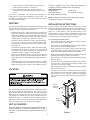
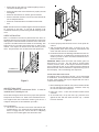
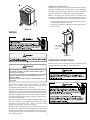
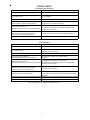
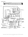
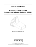
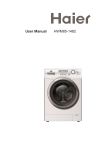
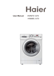
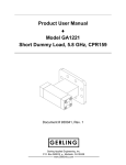
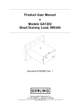
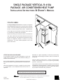
SINGLE PACKAGE VERTICAL R-410A
PACKAGE AIR CONDITIONER/HEAT PUMP
INSTALLATION INSTRUCTIONS & OWNER’S MANUAL
VTC/VTH SERIES
The Single Package Vertical Unit is a compact, through the
wall packaged HVAC system that can be ducted to individual
rooms. It’s slim 20” wide design uses minimal floor space and
installs in a closet having an exterior wall. Conditioned air
from a single unit can be ducted to multiple rooms. Each unit
is controlled by a standard wall thermostat.
These instructions give information relative to the SPVU unit
only. Refer to Wall Sleeve and Grille installation instructions
for those components. The manufacturer assumes no responsibility for equipment installed in violation of any code
requirements. For other related equipment refer to the
proper instructions.
ATTENTION INSTALLING PERSONNEL
As a professional installer you have an obligation to know the
product better than the customer. This includes all safety precautions and related items.
Prior to actual installation, thoroughly familiarize yourself with
this Instruction Manual. Pay special attention to all safety warnings.
Often during installation or repair it is possible to place yourself
in a position which is more hazardous than when the unit is in
operation.
Remember, it is your responsibility to install the product safely
and to know it well enough to be able to instruct a customer in
its safe use.
Safety is a matter of common sense...a matter of thinking before
acting. Most dealers have a list of specific good safety
practices...follow them.
The precautions listed in this Installation Manual are intended as
supplemental to existing practices. However, if there is a direct
conflict between existing practices and the content of this manual,
the precautions listed here take precedence.
This manual must be left with the owner of the equipment.
®
IO-381
March 2010
is a registered trademark of Maytag Corporation or its related companies and is used under
license to Goodman Company, L.P., Houston, TX. All rights reserved.
© 2010 Goodman Company, L.P.
IMPORTANT NOTE TO THE SERVICER
Contents
Note to Owner ........................................................ 2
Read this manual and familiarize yourself with the specific items
which must be adhered to before attempting to service this unit.
The precautions listed in this Installation Manual are intended as
supplemental to existing practices. However, if there is a direct
conflict between existing practices and the content of this
manual, the precautions listed here take precedence.
Note to Servicer ...................................................... 2
Features ................................................................ 3
Location ................................................................ 3
Unit Accessories ....................................................... 3
NOTE: HW Units: State of Massachusetts
Installation Instructions ............................................. 3
248CMR code of the State of Massachusetts requires
Wiring .................................................................. 5
a pump timer (60 seconds on every 6 hours). Contact
Operating Instructions ............................................... 5
your representative for a wiring diagram.
System Checks ........................................................ 6
Maintenance and Cleaning .......................................... 7
RECOGNIZE THIS SYMBOL
Obtaining Service ..................................................... 7
AS A SAFETY PRECAUTION.
Wiring Diagram ........................................................ 8
IMPORTANT NOTE TO THE OWNER
This manual is to be used by qualified, professionally trained
HVAC technicians only. Goodman does not assume any responsibility for property damage or personal injury for improper
service procedures or services performed by an unqualified
person.
IMPORTANT NOTES:
Your warranty certificate is also supplied with the unit.
Read the warranty carefully and note what is covered.
Keep the warranty certificate in a safe place, so you can
find it, if necessary.
Before using this manual, check the serial plate for
proper model identification.
TRANSPORTATION DAMAGE
THE INSTALLATION AND SERVICING OF THIS EQUIPMENT
The SPVU is shipped in one package, completely assembled.
Material in this shipment has been inspected at the factory and
released to the transportation agency in good condition. When
received, a visual inspection of all cartons should be made
immediately. Any evidence of rough handling or apparent
damage should be noted on the delivery receipt and the material
inspected in the presence of the carrier’s representative. If
damage is found a claim should be filed against the carrier
immediately.
MUST BE PERFORMED BY QUALIFIED, EXPERIENCED TECHNICIANS ONLY.
Due to policy of continual product improvement, the
right is reserved to change specifications and design
without notice.
In the event of damage, the consignee should:
1. Make notation on delivery receipt of any visible damage to
shipment or container.
2. Notify carrier promptly and request an inspection.
3. In case of concealed damage, carrier must be notified as
soon as possible—preferably within 5 days.
4. File the claim with the following supporting documents
within the 6 month statute of limitations.
a. Original Bill of Lading, certified copy, or indemnity
bond.
b. Original paid freight bill or indemnity in lieu thereof.
2
c. Original invoice or certified copy thereof, showing
trade and other discounts or reductions.
The unit is shipped in one carton. Optional accessories to
complete a particular installation are the following:
d. Copy of the inspection report issued by carrier’s
representative at the time damage is reported to the
carrier
Optional Accessories
Louvered Grille
Freeze Sensor
Non-Louvered Grille
Access Return Air Grille
60° Room Temperature Limiter
The carrier is responsible for making prompt inspection of
damage and for a thorough investigation of each claim. The
distributor or manufacturer will not accept claims from dealers
for transportation damage.
NOTE: Consult sales literature for the appropriate voltage
and amperage selections, if applicable.
FEATURES
INSTALLATION INSTRUCTIONS
This unit has many features which are different than those found
on conventional units. The servicer must be familiar with these
features in order to properly service the unit.
To ensure that the unit operates safely and efficiently, it must
be installed, operated and maintained according to these installation and operating instructions and all local codes and ordinances or, in their absence, with the latest edition of the
National Electric Code. The proper installation of this unit is
described in the following sections. Following the steps in the
order presented should ensure proper installation.
• Random restart delay - These units employ a random reset
timer which delays unit operation up to 3 minutes following
initial power application. Electronic thermostats may also
employ internal reset timers which may further delay any
changes which are made to the operation of the unit.
Pre-installation Considerations
• Automatic 3-minute compressor lockout - After the compressor cycles off, it will not restart for three minutes. Additional delays may be experienced if using an electronic digital thermostat.
• Ensure that properly sized duct work is in place to mate to
the supply connection on the SPVU.
• Remove the two clips holding the unit to the shipping pallet
and remove unit from the shipping pallet.
• Low ambient compressor lockout - When the outdoor ambient temperature is below 40 degrees F, the low ambient
compressor lockout switch will keep the compressor from
energizing in either cooling or heat pump mode.
• Before setting unit into closet, remove upper side access
panels and inspect the evaporator blower to ensure that the
wheel turns freely without rubbing on the housing.
• Direct drive, multi-speed blower - The proper speeds have
been preset at the factory for heating and cooling. Refer to
wiring diagram for recommended blower speeds for specific
models.
• Remove the styrofoam shipping block supporting the blower
assembly and replace the upper access panels.
• Condensate Drain - This unit comes with factory installed
drain tubing installed on the bottom of the unit. This tubing
drains from a trap at the bottom of the condenser section.
• Check all electrical connections and ensure the condenser
fan turns freely. Note nameplate voltage, amperage and
fuse size for proper power supply.
• Remove front access panel and remove packing and quick
disconnect plug.
• If ducted return air is required, bend out the intake air flanges
90° away from the unit.
LOCATION
• A outdoor air vent panel is located on the lower left side
unit. Remove one screw and rotate the plate to expose the
desired amount of vent opening. Tighten the remaining
screw. Place the removed screw in the open screw hole on
the unit.
Ducted
Return Air
Flanges
Provisions should be made to allow access to the indoor side of
the unit for installation and inspection. The closet or access
panel opening must be centered with the exterior wall opening
and at least 24” wide by 84” tall. Three (3) inches of unobstructed space is required on all sides of the SPVU to allow for
adequate air flow. At least 27 inches of unobstructed space
should be provided in front of the access door to permit removal
of the unit should repair and inspection be required.
Outdoor
Air Vent
UNIT ACCESSORIES
This unit is designed for through-the-wall installation in new or
existing buildings. To complete the installation of this unit, a
wall sleeve, an architectural grille, thermostat and a filter are
required.
Figure 1
3
• Ensure that the wall sleeve is installed squarely and is secure before installing the unit.
• Ensure the sleeve seal on the wall sleeve is properly secured
and aligned.
• Ensure the architectural or outdoor grille is installed.
• Ensure a minimum clearance of three (3) inches around the
unit for adequate airflow.
• Ensure the condensate drain is unobstructed and leakfree.
NOTE: The wall sleeve has a 3/4 NPT nipple located in the bottom
for connection to the drain. A trap may be required in the
condensate drain line to prevent sewer gas from escaping into the
room.
SLEEVE INSTALLATION
Refer to installation instructions packed with wall sleeve to
assemble and mount it in the wall. Ensure that the construction
debris guard is removed and that the bottom of the wall sleeve
is pitched 1/2 bubble toward the outside of the building. This
angle forces any rain water that might enter to drain to the
outside. Also inspect the bottom of the wall sleeve pan and
drain. They should be clear of obstruction and operational.
Figure 3
2. Connect properly sized electrical service to the quick disconnect.
3. Seal any openings that may exist. If the unit is not completely sealed, water and/or outside air could infiltrate the
closet and cause the unit to malfunction.
4. Install ductwork onto unit discharge and ensure that the connection is leak free. A flexible boot connection may be desirable to provide for more convenient installation and removal from the unit.
IMPORTANT NOTE: Check the indoor and outdoor grilles for
obstructions to air flow. The unit must be located where
curtains, furniture, trees, or other objects cannot block the air
flow to and from the unit. If air is obstructed and/or deflected
back into the unit, the air conditioner’s compressor may cycle on
and off rapidly. This could damage the compressor.
1/2 Bubble Tilt
INTAKE AIR FILTER INSTALLATION
An intake air filter is required for this unit. Do not use pleated
or media filters. Do not operate the unit without one. An intake
air filter, filter bracket and clip are shipped with the unit to
complete this installation.
Figure 2
1. Before installing the intake air filter, insert the filter bracket
into the slots below the evaporator. Install the filter clip
into the slots above the evaporator.
ARCHITECTURAL GRILLE
This model requires an Architectural Grille. It must be
installed before installing the unit.
2. Place a 20” x 24” x 1” filter into the filter bracket and tilt
outwards.
The architectural grille directs air flow for proper unit operation
3. At the same time, tilt up the filter clip, place the filter
against the unit and then lower the filter clip. It should
hook over the filter.
and protects the outdoor coil. Refer to the Installation Instructions supplied with the architectural outdoor grille kit for a
complete description of the installation procedure.
Unit Installation
1. Lift the unit onto the base of the sleeve and slide the unit
forward until it is 1/2” away from the top inside edge of the
sleeve to engage the seal. Ensure the unit is completely
seated on all four sides against the wall sleeve seals.
4
THERMOSTAT INSTALLATION
Install a factory approved or equivalent thermostat according to
directions furnished with the thermostat. The thermostat
should be located on an inside wall where it cannot be affected
by drafts, sunlight or any other heat producing appliances.
NOTE: Heat Pump units operate with the reversing valve
energized in the HEATING mode. The thermostat must be wired
or configured accordingly or the unit will not operate properly.
1. Connect thermostat wires to the thermostat following the
wiring diagram attached to the unit.
2. Connect low voltage thermostat wires from remote thermostat to the unit.
Figure 4
WIRING
Low Voltage
Thermostat
Wires
Figure 5
OPERATING INSTRUCTIONS
Operation of the unit is automatic and will provide heating and
cooling depending on the setting of the thermostat.
WARNING
THIS AIR CONDITIONER IS NOT MEANT TO PROVIDE UNATTENDED COOLING OR
LIFE SUPPORT FOR PERSONS OR ANIMALS WHO ARE UNABLE TO REACT TO
THE FAILURE OF THIS PRODUCT.
THE FAILURE OF AN UNATTENDED AIR CONDITIONER MAY RESULT IN EXTREME
HEAT IN THE CONDITIONED SPACE CAUSING OVERHEATING OR DEATH OF
PERSONS OR ANIMALS.
PRECAUTIONS MUST BE TAKEN TO WARN OFF OR GUARD AGAINST SUCH AN
OCCURRENCE.
All wiring must comply with local and national code requirements. Any alteration of the internal wiring will void UL
certification and manufacturer’s warranty.
Nameplate data indicates the operating voltage, phase, ampacity,
maximum over current protection and minimum voltage. Units
must never be installed or operated where voltage exceeds the
nameplate voltage by more than 10%. Failure of the compressor
as a result of operation with improper voltage voids the compressor replacement warranty.
The unit comes with a factory-supplied quick disconnect, however, the contractor is responsible for providing over current
protection on the branch circuit. Refer to the unit wiring
diagram for single point electrical connection.
These units are provided with a Class 2 transformer for 24 volt
control circuits. Should any add-on equipment also have a Class
2 transformer furnished, care must be taken to prevent interconnecting outputs of the two transformers by using a thermostat
with isolating contacts.
5
SYSTEM CHECKS
COOLING/ELECTRIC HEAT UNITS
POINT CHECK
ACTION
Set thermostat system switch to OFF position
None. Unit does not come on.
Set fan switch to ON
Indoor blower operate after random reset timer
cycle is complete.
Set fan switch to AUTO
Indoor blower de-energizes.
Set system switch to COOL and
lower thermostat set point to coldest setting.
The compressor, outdoor fan and indoor blower
energizes after a 3-minute startup delay.
The compressor and outdoor fan de-energizes.
Set thermostat set point to a
The indoor blower remains operational for an additional 45
temperature warmer than current room temperature
seconds, then de-energizes.
Move system switch to HEAT.
Raise thermostat set point to a temperature
warmer than current room temperature.
The indoor blower and electric heating elements energize.
Return system switch to OFF position.
Unit de-energizes. System check is complete.
HEAT PUMP UNITS
POINT CHECK
ACTION
Set thermostat system switch to OFF position
None. Unit does not come on.
Set fan switch to ON
Indoor blower operate after random
reset timer cycle is complete.
Set fan switch to AUTO
Indoor blower de-energizes.
Set system switch to COOL and
lower thermostat set point to coldest setting.
The compressor, outdoor fan and indoor blower
energizes.
The compressor and outdoor fan de-energizes.
Set thermostat set point to a
The indoor blower remains operational for an additional 45
temperature warmer than current room temperature
seconds, then de-energizes.
Move system switch to HEAT.
Raise thermostat set point to a temperature
warmer than current room temperature.
The compressor, reversing valve, outdoor fan
and indoor blower energizes.
Raise set point to more than 2 degrees.
Electric heaters energize. Determine by attaching
an amp meter to the electric supply and reading the increased
amperage.
Lower set point to less than room temperature.
Unit de-energizes
Return system switch to OFF position.
Unit de-energizes. System check is complete.
If any of these checks fail, contact an authorized servicer.
6
MAINTENANCE AND CLEANING
Intake Air Filter
The intake air filter is disposable. It should be changed
monthly during the heating and cooling seasons or more
frequently if unusual conditions are encountered. To replace
the filter, check with your local dealer.
To remove the filter:
1. Turn the unit OFF.
2. Lift up the filter clip with one hand and tilt out the filter
with the other.
Reverse this procedure to reinstall the filter.
Compressor
The compressor is hermetically sealed, permanently lubricated and requires no additional oiling. If vibration noise is
a problem, loosen the compressor mounting nuts until
vibration stops. Be sure nuts still secure the compressor to
the mounting plate.
Periodic Maintenance
Clean the outdoor coil of foreign material such as lint, dust,
leaves or other obstructions as necessary.
Check drain line and removing obstructions as necessary.
If servicing or major repairs are required, the complete unit can
be removed as follows:
OBTAINING SERVICE
1. Disconnect the electrical power circuit supplying the unit.
In the event this unit requires repair or servicing beyond what is
covered in this manual, contact an authorized service organization.
2. Remove Quick Disconnect and low voltage thermostat connection.
3. Remove rear access panel.
To obtain an authorized servicer, contact your sales representative or agency.
4. Remove supply duct from top of unit.
5. Slide unit out of sleeve and closet.
Reverse this procedure to reinstall the unit.
7
WIRING DIAGRAM
WARNING
HIGH VOLTAGE!
DISCONNECT ALL POWER BEFORE SERVICING OR INSTALLING THIS
UNIT. MULTIPLE POWER SOURCES MAY BE PRESENT. FAILURE TO
DO SO MAY CAUSE PROPERTY DAMAGE, PERSONAL INJURY OR DEATH.
YEL
YEL
EVAP.
MOTOR
COND.
MOTOR
COMPRESSOR
BRN
HEATER 1
RED
YEL
YEL
BLK
BLK
BRN
BLK
CAP OFF ANY
UNUSED SPEED TAPS
BLK
RED
BLUE
BLK
H C F
L1
BLK
YEL
YEL
L1
COMP
HTR2
COND
EVAP
LO
EVAP
HI
L1
L2
YEL
L2
GRD
L1
208-240V-1PH-60HZ
POWER SUPPLY
HTR1
L2
A FACTORY SUPPLIED JUMPER IS
PLACED BETWEEN FD AND RC AND
MUST BE REMOVED WHEN INSTALLING
THE FRONT DESK SWITCH.
L1
DISCONNECT
BLK
COM R G
Y W2
FD RC RS
INDOOR
RED
RED
OUTDOOR COIL
(NC)
COOLING
LOCKOUT
OUTDOOR
DEFROST
BRN
BRN
REVERSING
VALVE
SOLENOID
GRN
BRN
VIOLET
GRN WHT
BLU
RED
ORG
INDOOR COIL
(NO)
BRN
FACTORY WIRING
FIELD WIRING
C
R G
Y W2 B
NOTE: "C" LEAD MAY BE
REQUIRED FOR ELECTRONIC
THERMOSTATS
24V CLASS 2 WIRING
LOW TEMP
LOCKOUT (NO)
R G Y W2 *
*REVERSING VALVE MUST BE
ENERGIZED IN THE HEATING MODE.
CONNECT PER THERMOSTAT INSTRUCTIONS.
24V HEAT PUMP THERMOSTAT
(R.V. ENERGIZED ON CALL
FOR HEAT)
FRONT DESK
SWITCH (OPTIONAL)
(FIELD INSTALLED)
AMBIENT ROOM
SENSOR (OPTIONAL)
(FIELD INSTALLED)
(NO)
VTH12
Wiring is subject to change. Always refer to the wiring diagram on the unit for the most up-to-date wiring.
8