1
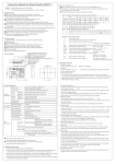
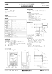
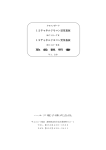
No.QT32-11002
MNC-100E
[Compact type one axis controller]
【User’s manual】
Changing history of user’s manual
Changes
Date of change
Description of change
Changed by
Attention on Safety
Please read this user’s manual carefully before using this device.
Warning
Please keep the followings and use safely to avoid a
fatal accident.
● Do not use or leave it unattended after
disassembling or damaging this unit.
The above might
cause an electrical
shock or an accident.
We will not be
responsible for repair
if the unit is
disassembled by the
customer.
● Avoid having metals and other foreign
objects enter into the device.
The above might
cause fire, electric
shock or accidents.
● Do not touch the unit with wet hand.
The above might
cause electric shock
or accidents.
Attention on safety
Please read this user’s manual carefully before using this unit.
Please keep the followings and use safely to avoid an
Attention accident.
●
Do not use or store the unit near by
corrosive gas, watery or chemical
place.
●
薬品
It may cause fire,
electric shock or
accident.
Do not use or store this unit in a
place of direct rays of the sun.
It may cause an
accident.
● Confirm the input voltage and wiring
before power on.
Wrong wiring or
input voltage may
cause fire or
accident.
● Earth
Earth (D class
earth) or connect
with protective
earth in case of
the product
having protective
earth terminal to
avoid electric
shock.
Attention on usage
Please read this user’s manual before using this device.
Attention
Please keep the following and use safely to avoid an
accident.
● Do not use or store this device in a
dusty place.
This device is not
constructed
dustproof.
Operating in dusty
place causes the
accident.
● Do not give the device a big shock.
This is a precision
device and it should
not be dropped or
given a big shock. It
causes the accident.
● Do not use or store it in a place where
the temperature might rise too high or
too low.
The operating
temperature is
0°~40°C and the
storage
temperature is
0°~60°C.
Avoid extreme temperature changes.
● Do not use or store it in a place where
the humidity might rise too high or too
low.
The operating
humidity should be
within 30% - 80%. The
storage humidity
should be within 20% 90%.
● Avoid condensation of dews.
Bringing the device
into a place of high
humidity or a place
where temperature
changes suddenly will
cause condensation of
dews.
● Take measures against noises.
Noises will cause malfunctions and
accidents.
Use the power supply
which is not connected
to a noise generating
device.
● Use shielded wires for
wiring. Make them
as short as possible.
Use the twisted pair
wires for the clock
outputs.
● In case of AC type
products, separate
power cable (AC) from
signal line (DC) more
than 20cm.
● Earth if the
products have earth
terminal.
20cm以上
AC
信号
1. FOREWORD........................................................................................................................1
1-1. CHECKING CONTENTS OF PACKAGE..................................................................................1
1-2. SETTING OF LCD DISPLAYABLE LANGUAGE......................................................................1
2. SPECIFICATION ................................................................................................................2
3. CONNECTOR PIN ASSIGNMENT.....................................................................................3
3-1 I/O CONNECTOR ...............................................................................................................3
3-2 CONNECTOR FOR DRIVER..................................................................................................4
3-3 POWER CONNECTOR .........................................................................................................4
4. DIMENSIONS .....................................................................................................................6
5. FUNCTION .........................................................................................................................7
6. OPERATION MODE ...........................................................................................................9
7. HOW TO OPERATE ..........................................................................................................10
7-1. HOME SEARCHING.........................................................................................................10
7-2. CURRENT POSITION CLEAR ............................................................................................10
7-3. SCANNING ....................................................................................................................11
7-4. INDEX MOVING ..............................................................................................................12
7-5. POSITION DATA MOVING ................................................................................................13
7-6. POSITION DATA STORING ...............................................................................................14
7-7. POSITION DATA EDITING ................................................................................................15
7-8. SPEED SETTING .............................................................................................................16
7-9. SYSTEM SETTING...........................................................................................................17
7-9.-1 System setting (System setting) .................................................................... 17
7-9-2. System (Data clear)........................................................................................ 19
7-11. REMOTE ......................................................................................................................21
7-11-1. D0, D1, D2 and D3 setting signal ................................................................ 22
7-11-2. P_ST ............................................................................................................. 22
7-11-3. S_ST ............................................................................................................. 24
7-11-4. H_ST............................................................................................................. 24
7-11-5 P_CLR ........................................................................................................... 24
8. WIRING DIAGRAM ..........................................................................................................25
9. INPUT OUTPUT SIGNAL CIRCUIT DIAGRAM .............................................................26
10. HOME SEARCH PATTERN............................................................................................27
11. ERROR DISPLAY LIST...................................................................................................28
12. OPTIONAL METAL PLATE DIMENSION.....................................................................29
13. OPTIONAL CABLE.........................................................................................................31
1. Foreword
Thank you using our MNC-100E, Compact type one axis controller, this time.
Please read this manual thoroughly in prior to using this unit and operate this unit
correctly.
1-1. Checking contents of package
MNC-100 includes the following items. Please check that all of them are included in
the package. We are carefully packaging the products but please contact us or our
agencies if some accessories are missing or damaged.
・Main unit,
MNC-100
・Fixture,
MNC-100-F
・Connecting tool,
233-332
・Housing (for CN2)
x 1 set. See Page 4.
・Housing (for CN3)
x 1 set. See Page 4
・User’s manual
x1
MNC-100J
MNC-100E
x1
x 1 set (2 pieces)
x 1 (WAGO brand)
Japanese display type
English display type
1-2. Setting of LCD displayable language
LCD displayable language of MNC-100 is set as English display type at factory default.
When you require to change into Japanese display type, please power DC+24V on
pushing ENT and ▲ buttons of MNC-100 main body at same time. MNC-100 displays
to select displayable language setting. Please select displayable language(Japanese or
English) by pushing ▲ ▼ buttons.
Then please push ENT button.
When MNC-100 enters into displayable language setting, the LCD displays as follows.
(In case of English selecting)
(In case of Japanese selecting)
Select Language
Select Language
エイコ゛ : English
ニホンコ゛: Japanese
1
2. Specification
The specification of MNC-100 is shown below.
Items
Control system
Number of axes
controlled
Control Motor
Program capacity
Description
Microprocessor control system (Z80 compatible)
One axis
Stepping motor
15 positions
Position
(Position storing at Serial EEP-ROM, writing
data
times 105)
Acceleration
deceleration system
Trapezoidal or triangle
Command system
Key input, Remote start signal (Sequential start / Specific
position start)
Moving distance
command system
Absolute and incremental by specification
Remote function
Panel control
Start speed and
maximum speed
Acceleration
deceleration speed
Setting range of Moving
distance
Setting range of
a moving command
Driver I/F
Mechanical sensor I/F
Home search, Scanning, Position data moving, Emergency
stop, Current position clear
Home search, Current position clear, Scanning, Index moving,
Position data moving, Position data editing, Position data
storing, Speed setting.
1 to 65,535 Hz.
1 to 1,900 Hz./msec.
Available moving range setting (0 to ± 8000000)
0 to ±8000000
Input
Output for clock (Open collector)
1 clock / 2 clocks
Both ends over-run, Home
Photo coupler isolated
5mA internal power source (+24V) used
8 points
External start signal (H_ST, S_ST, P_ST)
Emergency stop signal (EMER)
Specific position signal (D0 to D3)
Photo coupler isolated
Open collector output, 13mA, Less than
3 points
dielectric strength 35V
Error output(ERR), Ready output(RDY),
moving output(MOVE)
LCD showing, 16 characters x 2 lines
Systems setting, Data clear
DC+24V±10%, Less than 0.15A
Operating
Temperat 0 to 45 "C
30 - 80%
Humidity
ure
Storing
0 to 60 "C
20 - 90%
101(W) x 98(D) x 40.6(H)mm (excluding protuberance)
500g
Exclusive I/O
Output
Display
Parameter function
Input power
Environment
(without condensation)
Dimension
Weight
2
3. Connector pin assignment
3-1 I/O connector
Item
Connector
Type
Manufacturer
WAGO
233-416
16
Ref.
1
COM
COM
ERR
MOVE
RDY
REV
FOR
HOME/P_CLR
D3
D2
D1
D0
EMER
P_ST
S_ST
H_ST
Pin
No.
16
15
14
13
12
11
10
9
8
7
6
5
4
3
2
1
Signal
name
H_ST
S_ST
P_ST
EMER
D0
D1
D2
D3
HOME /
P_CLR
FOR
REV
RDY
MOVE
ERR
COM
COM
Description
Starting of Home search
Starting of Scanning
Starting of Position data moving
Emergency Stop, Remark 1
When scanning, data 0 and data 1
Data 0
specify the moving direction.
Data 1
When position data moving, data 0
Data 2
to data 3 specify position number.
Data 3
Input /
Output
Circuit
Input
Circuit
diagram
2, P.26
Output
Circuit
diagram
3, P.26
Home / Current position clear
Forward overrun
Reverse overrun
Ready output
Moving output
Error output
Input / output common
Input / output common
Remark 1: Please use with the status of normal close (B connection), when normal
operating.
Please connect with COM terminal if it is not used. If this unit is not
the status of normal close, “Emergency Stop” is displayed and this unit
does not work.
3
3-2 Connector for driver
Item
Post
Housing
Contact
Type
S6B-XH-A-1
XHP-6
SXH-001P-P0.6
Manufacturer
J.S.T. Mfg Co.,Ltd.
- do - do -
1
Ref.
Accessory
〃
6
CCW CW/CCW+
CCW CW/CCWCW PULSE+
CW PULSEHOME+
HOME-
Pin
No.
1
2
3
Signal name
HOMEHOME+
CW PULSE-
4
CW PULSE +
5
CCW CW/CCW-
6
CCW CW/CCW+
Remark 2:
Description
Home position, Remark 2.
Input /
Output
Circuit
Input
Circuit diagram 2,
P. 26
CW clock output
Clock output in case of 1
clock setting.
Output
CCW clock output
Direction output in case of 1
clock setting.
Circuit diagram 1,
P. 26
HOME- and HOME+ are used only in the combination of our motor
cylinder and driver. In case of universal usage, please use HOME of I/O
connector.
3-3 Power connector
Connector, S4B-XH-A-1, JST
Item
Post
Housing
Contact
Type
S4B-XH-A-1
XHP-4
SXH-001P-P0.6
Manufacturer
J.S.T. Mfg Co.,Ltd.
- do - do -
1
4
+24V
+24V
0V
0V
4
Ref.
Accessory
-do-
Pin No.
1
2
3
4
Signal Name
0V
0V
+24V
+24V
Description
Input 0V
- do Input +24V
- do -
5
H_ST
S_ST
P_ST
EMER
D0
D1
D2
D3
HOME/P_CLR
FOR
REV
RDY
MOVE
ERR
COM
COM
4. Dimensions
40.6
2
MNC -100
98
CCW CW/CCW+
CCW CW/CCWCW PULSE+
CW PULSEHOME+
HOME-
LCD Br ightness adjustw indow
PO
WER ERROR MOVE
MODE
ENT
MYCOM ,INC . MADE
+12V~24V
+12V~24V
0V
0V
IN JAPAN
15
8
77
98
Frame Ground
F ix ing screw (M3)
101
5
5
1
100
14.68
4-M3
(F ix ing p lace of opt ion)
4-1 Accessories for fixing
MNC-100-F
87
58
2
14.5
4
30
5
4
10
2-R2
77 ±0 .1
5
6
2- φ4.0
φ6.5(90゜f lush)
5. Function
After power on, MNC-100E displays “REMOTE” and becomes the status of remote
operation available.
Pushing “MODE” key enters panel operation mode.
Eight kinds of modes, “HOME SEARCH?” -> ”CLEAR CUR. POS.?” -> ”SCAN
DRIVE” -> ”INDEX DRIVE?” -> ”POSITION DRIVE?” -> ”POSITION SAVE?” ->
”POSITION EDIT?” -> ”SPEED SET?” -> ”SYSTEM SET?”, are displayed
sequentially by each pushing “MODE” key or ▼ key.
Pushing “ENT” key at the
required mode can decide the mode. To exit the mode, please push “MODE” key.
Pushing “MODE” key for more than one second returns to “REMOTE” mode.
Outline of each function is explained as follows;
HOME SEARCH
This returns to Home position.
RESET ZERO. POS.
This clears current position to zero.
SCAN DRIVE
This
drives
for
the
specified
direction
with
acceleration and maximum speed during pushing
▲ or ▼ key of front panel.
INDEX DRIVE
Each pushing ▲ or ▼ key of front panel drives
each specified moving distance.
POSITION DRIVE
This moves to the place of position data number
which
is
stored
at
“POSITION
SAVE
and
“POSITION EDIT”.
POSITION SAVE
This stores the current position as teaching
function. The numbers of storing position is 1 to 15,
total 15 points.
POSITION EDIT
In this mode, position data editing, speed number
setting, skip function setting and editing are
available.
SPEED SET
In this mode, speed settings for three modes (Home
search, Scanning and Index) and speed Nos. 1 to 10,
total 13 various, are available.
start
speed,
maximum
Speed setting sets
speed,
acceleration
deceleration speed.
SYSTEM SET
In this mode, system setting (Home position, Limit
sensor logic, Clock type, Forward direction and
7
Selection of home clear function) and deleting and
initializing data are available.
REMOTE
In this mode, Home searching, Scanning, Position
data moving and Emergency stop are controllable
by external input/output signal.
Please push “MODE” key for more than one second
when entering into remote operation mode from
panel operation mode.
8
6. Operation mode
REMOTE
HOME SEARCH?
RESET ZERO?
SCAN DRIVE?
INDEX DRIVE?
POSITION DRIVE?
POSITION SAVE?
POSITION EDIT?
SPEED SET?
SYSTEM SET?
For deta i ls , 7-11
For deta i ls , 7-1
For deta i ls , 7-2
For deta i ls , 7-3
For deta i ls , 7-4
For deta i ls , 7-5
For deta i ls , 7-6
For deta i ls , 7-7
For deta i ls , 7-8
For deta i ls , 7-9
9
7. How to operate
4 keys on front panel operates in each menu and each moving mode. 4 keys in each
menu almost assign “ENT” key: “Decision”, “MODE” key: “Cancel”, ▲ or ▼ key:
“Select” or “Move”. Depending on items to set, there is different assignment to operate.
7-1. Home searching
HOME SEARCH?
ENT
Home search
ENT
(Home search f in ish)Home search
Home searching
“HOME SEARCH?”
When executing Home searching, Push “ENT” key
to enter the mode.
“Home search”
Push “ENT” key to start home searching.
“Home searching”
This is display during home searching
The moving speed of home searching refers the setting of “H”(Home searching) in
“SPEED SET”. Refer “Speed setting”(p.16)
7-2. Current position clear
RESET ZERO?
ENT
Reset ZERO
Sure ? Yes
(Current pos it ion c lear)
”RESET ZERO?”
ENT
When “ENT” Key is pushed, it goes to current position clear
mode.
"Reset ZERO"
This clears current position to Zero and set as imaginary
home.
10
7-3. Scanning
▼
(Scann ing)
Scan drive
0
(F in ish of scan dr ive) MODE
ENT
▼
ENT
MODE
Scan drive
0
Low
▼
(Start ing speed)
▼
SCAN DRIVE?
“SCAN DRIVE?”
Push “ENT” key to enter scanning mode.
“Scan drive”
Pushing ▲ or ▼ key starts scanning.
The figures show the pulse numbers of current position.
“Scan drive Low”
Pushing ▲ or ▼ key starts scanning with start speed.
“Low” display is switched by each “ENT” key pushing.
The moving speed of scanning refers the setting of “S”(Scanning) of “SPEED SET”.
Refer “Speed setting”(p.16)
Pushing “ENT” key during stop switches moving with start speed or moving with
accel/decel. In case of moving with start speed, “Low” is displayed.
About key control of ▲ and ▼ key
▲ key:
plus direction
▼ key:
minus direction
If it is pushed for less than 1 set., it is jog movement.
11
7-4. Index moving
Index
I:0000000Pulse
ENT
MODE
(Indexmov ing f in ish)
▼ ENT
MODE
(Sett ing of Indexmov ing)
ENT shou ld be pushed formore than one sec .
Index drive
0
▼
(Feed ing)
▼
ENT
▼
INDEX DRIVE?
“INDEX DRIVE ?”
Push “ENT” key to enter indexing mode.
“Index”
The moving distance is set by keys of “MODE”,▲, ▼ and
“ENT” key.
If “ENT” key is pushed for more than 1 sec., the moving
distance is decided.
“Index drive”
Pushing ▲ or ▼ key starts index moving
The figures show the current position. Pushing “ENT” key
returns to the setting mode of moving distance to change the
moving distance.
The moving speed refers the setting by “I”(Index moving) of “SPEED SET”. (Ref. Speed
setting, P16)
When it enters into index moving mode at first time, or “ENT” key is pushed during
stopping status, the moving distance setting window is displayed. (Ref. Value setting
key operation, P20)
12
7-5. Position data moving
ENT
▼
Pos.Num.Select
:
P 0 ±0000000, 0 (Se lect pos it ion number)
▼
POSITION DRIVE?
ENT
(Mov ing f in ish) Position driving
0
“POSITON DRIVE ?”
Push “ENT” key to enter position data moving mode.
“Pos. Num. Select”
▲ and ▼ keys select position number and “ENT” key
decides the position. Pushing “ENT” key moves to the
selected number.
“Position driving”
The current position is displaying during moving.
The moving speed refers the speed of speed number which was set when data storing.
Refer "Position data storing“(p.14) and “Position data editing”(p.15)
When “Absolute” is set in “Coordinate” of “System set”, it moves to absolute position
from zero. If “Incremental” is set, it is incremental setting and each movement clears
current position.
Position number selected display
DISPLAY -> "P 0: 0000000, 0 "
Display
Description
P(I) 0 Position data number
P stands for position setting and I
stands for index setting.
: No / Yes display of skip. (No : / Yes *)
0000000 Position data (Pulse numbers)
0 Speed setting number
* Description of display of position number selected
13
7-6. Position data storing
ENT
▼
Pos.Num.Select
P 0: ±0000000, 0 (Pos it ion number se lect)
▼
POSITION SAVE?
ENT
▼
Speed Num.Select
:
:
0 (Max 00000) (Speed number se lect)
▼
ENT
▼
Move Mode
Point setting (Pos it ion / Index se lect)
▼
▼
(Yes/No se lect)
▼
ENT
Position save
(Sav ing vo id ) Save ? :Yes
N ENT
Y ENT
(Sav ing f in i sh )
“POSITION SAVE ?”
Push “ENT” key to enter position data storing mode.
“Pos. Num. Select”
Select position number.
“Speed Num. Select”
Select speed number.
“Move Mode”
Select how to specify. When incremental coordinate is
selected,
this
is
not
displayed.
Refer
"System
setting"(p. 17).
“Save ?”
Select YES or NO.
When “Yes “ is decided, the current position and selected speed number are stored at
selected speed number.
If “Incremental” is set at “Coordinate select” in “System setting”, the current position is
cleared to Zero after storing and finish. Refer "System setting"(p. 17)
*Please refer P. 13, “Description of display of position number selected” display for the
detail of “Position number select”.
14
7-7. Position data editing
Pos.Num.Select
P 0: ±0000000, 0
ENT
Position edit
P 0: ±0000000
▼
(Pos it ion number se lect)
▼ ENT
MODE
(Pos it ion data ed it)
▼
ENT
▼
POSITION EDIT?
ENT is pushed one second ormore .
▼
Speed Num.Select
0: (Max:00000) (Speed number se lect)
▼
ENT
Position edit
(Ed i t ion vo id ) Save ? :Yes
N ENT
▼
(Pos it ion/Mov ing d istance se lect ion)
▼
(Yes/No Se lect ion)
▼
ENT
Move Mode
Point setting
▼
(No/Yes se lect ion)
▼
Position edit
Pos.Skip ?No
▼
ENT
Y ENT
(Ed i t ion f in i sh )
“POSITION EDIT ?”
Push “ENT” key to enter position data editing mode.
“Pos. Num. Select”
Select position number to edit.
“Position edit”
Edit the numbers of position.
“Speed Num. Select”
Select speed number.
“Pos. Skip ?”
Select No or Yes to skip or not to skip.
“Move Mode”
Select how to select.
“Save ?”
Decide Yes or No.
*Refer P. 13, “Description of display of position number selected” about display for the
detail of “POSITION EDIT” display.
*Refer P. 20, Value setting key operation for the detail of “Position edit”, key control
during position data editing.
*Skip function
Skip function relates remote control, Position date sequential execution. Refer P. 21,
Remote
The “No” or “Yes” setting of skip function is confirmable by symbol of “:” of “P 0: ±
0000000,0” display.
Invalid skip function(No) = “:”.
Valid skip function(Yes)= “*”
15
7-8. Speed setting
▼
Speed set select
0: (Max:00000) (Speed sett ing se lect ion)
ENT
Start speed
00000Hz
▼ ENT
MODE
(Speed sett ing)
▼
ENT
▼
SPEED SET?
ENT is pushed for one second ormore .
▼ ENT
MODE
(Speed sett ing)
▼
Maximum speed
00000Hz
ENT is pushed for one second ormore .
▼ ENT
MODE
(Speed sett ing)
▼
Ramp
ENT is pushed formore than 1 0
sec0
. 00Hz/mSec
“SPEED SET ?”
Push “ENT” key to enter speed setting mode.
“Speed set select”
Select speed number and “ENT” key decides the speed
setting.
“Start speed”
Set the start speed.
“Maximum speed”
Set the maximum speed.
“Ramp”
Set slow-down and slow-up speed.
Speed setting and speed number (1 to 10) of each mode of H(Home search),
S(Scanning) and I(Indexing) can be set by same procedure of the above.
The selected contents of speed setting are changed in order of start speed->maximum
speed->slow-up slow-down speed.
Refer P. 20, Value setting key operation for detail of value setting key control of
“Start speed”, “Maximum speed” and “Ramp”.
16
7-9. System setting
7-9.-1 System setting (System setting)
ENT
▼
System setting Y ENT System set
System?
:No
Home logic :NMOP (NO / NC se lect)
ENT
▼(No / Ye s Se le c t )
▼
System set
Limit logic:NMOP (NO / NC se lect)
▼
SYSTEM SET?
▼
▼
ENT
▼
System set
Clock type :1CLK (1 c lock / 2 c lock se lect)
▼
▼
(Va l id / Inva l id se lect)
▼
ENT
Software limit
Enable
▼
(CW / CCW se lect)
▼
ENT
System set
Direction :CW
ENT
▼ ENT
MODE
Software limit
Forward +0000000 (Uppe r mov ing l im i t se t t ing )
▼
ENT is pushed for one second ormore
▼ ENT
Software limit
MODE
Reverse -0000000 (Lowe r mov ing l im i t se t t ing )
▼
ENT is pushed for one second ormore
( Inva l id Save )
▼
(Yen / No se lect)
▼
ENT
System set
Seve ? :Yes
N ENT
▼
(Abso lu te / Incrementa l se lect)
▼
ENT
Coordinate
Absolute
▼
(Va l id /Inva l id se lect)
▼
Position clear
Enable
Y ENT
(Save f in i sh )
“SYSTEM SET ?”
Push “ENT” key to enter system setting mode.
“System ?”
Select Yes for system setting.
“Home logic”
Select NMOP or NMCL to set logic setting of home sensor.
“Limit logic”
Select NMOP or NMCL to set logic setting of limit sensor.
“Clock type”
Select 1CLK or 2CLK to set clock type.
“Direction”
Select CW or CCW to set forward direction.
“Software Limit”
This selects valid or invalid of moving limit setting. When
“Invalid” is selected, the following “Forward” and “Reverse”
setting are not displayed.
“Forward”
Set the numbers of pulses of the upper maximum moving limit
for forward direction.
“Reverse”
Set the numbers of pulses of the lower maximum moving limit
for reverse direction.
17
“Position Clear”
Select valid or invalid setting of position clear control at
stopping.
“Coordinate”
Select “Absolute” or “Incremental”.
“Save ?”
Select Yes or No to store. When No is selected at “Save ?”, the
changed data becomes invalid and previous setting remains.
Refer P. 20, Value setting key operation for detail of value setting key control of
“Forward” and “Reverse”.
18
7-9-2. System (Data clear)
ENT
▼
System setting
:No (No/Yes Se lect)
System?
▼
SYSTEM SET?
N ENT
System setting Y ENT
Data clear? :No
▼(No/Yes Se lect)
▼
:No (No/Yes Se lect)
▼
Y ENT
(C lear f in ish)
Data clear
Pos. Data?
Y ENT
(C lear f in ish)
▼
Data clear
Speed data? :No (No/Yes Se lect)
Y ENT
(C lear f in ish)
▼
Data clear
System data?:No (No/Yes Se lect)
Y ENT
(C lear f in ish)
Data clear
ALL data? :No
▼
N ENT
▼
N ENT
▼
▼
(No/Yes Se lect)
▼
N ENT
N ENT
“SYSTEM SET ?”
Push “ENT” key to enter data clear mode.
“SYSTEM ?”
Select No for data clear.
“Data clear ?”
Select Yes for data clear.
“Pos. Data ?”
Clear the stored position data.
“Speed data ?”
Clear the stored speed data.
“System data ?”
Clear to the initial system setting.
“All data ?”
clear above all items.
If Yes is selected at any stage, the display returns to “System ?” after the contents of
its stage is cleared.
If speed setting data and system setting are cleared, the initial setting is retrieved.
19
7-10 Value setting key operation
Key operation for value edition, for example position data editing and speed setting, is
as follows.
“ENT” key and “MODE” key move cursor to left and right to change the place. ▲ and
▼ keys increase or decrease the value on the place targeted by cursor.
The combination of 4 keys on panel edits the value. Pushing “ENT” key for more than 1
second decides the edited value and pushing “MODE” key for more than one second
cancels.
Continuing to push ▲ and ▼ keys repeats automatically.
De s c r ip t ion o f va lue se t t ing key ope ra t ion
MODE
A f igure up
Push ing 1 sec . ormore ex its
Va lue p lus
ENT
A f igure down
Push ing 1 sec . ormore enters .
Va luem inus
*Description of value setting key operation
20
7-11. Remote
External start signals (P_ST, S_ST, H_ST, P_CLR) can control position data moving,
scanning, home searching and current position clearing.
Setting signals of D0 to D3 specify the position data and the direction of scanning.
The rising timing of HOME/P_CLR signal can clear current position to zero only
when both the status of this controller is stop and the position clear function of
system setting is valid.
This function is useful for such moving to fixed direction
with fixed distance by fixed distance continuously. (Ref. System setting, P17).
When “Coordinate” in “System set” sets “Absolute”, this unit moves as absolute
position specification. At this time, the moving distance is accumulated by P_ST, and
S_ST signal input. Any of “Home search”, “Moving to Zero position” and
“Incremental” let current position zero. (Ref. System setting, P17).
When “Coordinate” in “System set” sets “Incremental”, this unit moves as
incremental position specification. The moving distance by signal input of P_ST and
S_ST does not accumulate and is cleared to zero just before each operation
starts.(Ref. System setting, P.17)
Timing chart of external signal
H_ST ,S_ST ,P_ST ,P_CLR
ON
t1
Un it (ms .)
t2
D0~D3
t3
READY
t4
ON
t5
MOVE(BUSY)
t1
0 ormore
t2
5 ormore
t3
1 or less
t4
0 ormore
t5
1 or less
ON
P_ST, S_ST, H_ST, and P_CLR signals are valid when READY signal outputs.
During movement, READY signal goes OFF and MOVE signal outputs.
MOVE signal output does not go ON while P_CLR is operating.
21
7-11-1. D0, D1, D2 and D3 setting signal
These are required setting signals for specifying position data number and direction
of scanning.
(0=OFF, 1=ON)
Number
setting
Sequential
start
1
2
3
4
5
6
7
8
9
10
11
12
13
14
15
D3
D2
D1
D0
0
0
0
0
0
0
0
0
0
0
0
1
1
1
1
1
1
1
1
0
0
0
1
1
1
1
0
0
0
0
1
1
1
1
0
1
1
0
0
1
1
0
0
1
1
0
0
1
1
1
0
1
0
1
0
1
0
1
0
1
0
1
0
1
FOR
REV
FOR(S)
REV(S)
D3
---------
D2
0
0
1
1
D1
0
1
0
1
D0
1
0
1
0
Table 2. Scanning direction setting
Table 1. Number setting
7-11-2. P_ST
This is the external start signal for position data moving.
P_ST signal should be inputted after setting signals of D0 to D3.
There are two various starting methods for position data moving. One is sequential
start and another is position setting start.
Sequential start:
Specify D0 to D3. (Ref. Table 1.)
This starts sequentially the position data which is specified at Skip Number by
position data editing. (Ref. “Position data editing”, P. 15)
Ex.)
Skip, No
Skip, Yes
Position data number
1, 2, 3, 7, 8, 9, 15
4, 5, 6, 10, 11, 12, 13, 14
In case of above setting, sequentially started position data numbers
are as follows:
1->2->3->7->8->9->15->1->…
Position setting start
Position data numbers (1 to 15) are specified by D0 to D3
22
(Ref. table 1)
This can move to the specified position. In this case, this
controller starts without relation to No or Yes of skip
setting which is specified by position data editing.
23
7-11-3. S_ST
This is an external start signal for scanning.
This moves to the direction specified by D0 and D1 (Refer Table 2) from the place
where S_ST signal goes ON. Then controller stops with deceleration at the place
where S_ST signal goes OFF.
If D2 sets ON, it moves with staring speed without slowdown / slowup.
7-11-4. H_ST
This is an external signal for home search.
Home search is started by the rising edge of H_ST signal without relation to D0 to
D3 settings.
7-11-5 P_CLR
This is a current position clear signal.
The rising edge of P_CLR signal clears the current position to zero without relation
to D0 to D3 setting.
This signal is valid only when both this controller is stopping status and the
position clear function is set valid by system setting. In case that the position clear
function is set invalid by system setting, there is no control. (Ref. System setting,
P.17)
24
8. Wiring diagram
Contro l ler
+5V
Dr iver
+CW PULSE
-CW PULSE
+CCW CW/CCW
ーCCW CW/CCW
M icro sw itches etc .
+24V
HOME
0V
COM
* Use twisted pair shield wire for the connection cable.
Opt ica l sensor etc .
HOME
+
ー
COM
+24V
0V
0V
+24V
Ex te rna l powe r supp ly
(24V)
Note: Connect with flame ground by all means. Refer 4. External dimension of P. 6
25
9. Input output signal circuit diagram
+24V
+5V
1K Ω
1SS181
+CW PULSE
+CCW CW/CCW
-CW PULSE
-CCW CW/CCW
0V
Circuit diagram 1
+24V
1K Ω
3Q66Q
1SS184 4 .7K Ω
0V
H_ST,S_ST,P_ST
D0~D3
HOME/P_CLR
FOR,REV,EMER
COM
Circuit diagram 2
+24V
+24V
10K
MOVE,RADY,ERROR
1SS181
RN1401
COM
3Q66Q
0V
Circuit diagram 3
26
10. Home search pattern
R everse
overrun
Forw ard
O verrun
H om e
M ax.speed
Start speed
1. Home search
normal position
from
Start
R everse m oving
Forw ard m oving
S tart speed
2. Home search from
Near home ON position
R everse m oving
Forw ard m oving
S tart
Start speed
3. Home search from the
position between Near
home and Overrun
R everse m oving
Forw ard m oving
4. Home search from
Overrun position
R everse m oving
Forw ard m oving
0.5sec wait
Start
S tart speed
Fig. of home search pattern
27
S tart
11. Error display list
LCD display
"Emergency stop"
Reason and Solution
The status of emergency stop signal is ON.
Please release the emergency stop signal. After release,
reset is activated and recovered.
"ForwardLimit Err"
"ReverseLimit Err"
Overrun limit is unusual
The moving intends to exceed the position of limit sensor
during moving.
Please push “MODE” key or please power off the controller
to release the error and move it reverse direction against
limit.
* ”Limit logic” setting of “System set” is wrong.
Please correct the logic setting.
* The wiring of overrun sensor is troubled.
Please confirm the wiring and correct.
"MNC-100Fatal Err"
This is unexpected error.
Please contact us.
28
12. Optional metal plate dimension
87
58
14.5
10
4
2
10
77 ±0 .1
32
17
32
5
4
2- φ4.0
φ6.5(90゜Counters ink)
5
5
R2 .
16 .5
16 .5
R2 .
5
7
35
5
5
Z shape metal plate (MNC-100-Z)
7
4-C2
120
100
4- φ4 .0
φ6 .5(90゜counters ink)
105
5
77 ±0 .1
5
18
2-C2
L shape metal plate (MNC-100-L)
29
14.6
100+0-0 .3
6.6
72.8
4- φ4
5
33
5
5
87
5
46.5
77 ±0 .2
DINレール
(Metal bracket plate for DIN rail), Figure of setting (MNC-100-D)
Note) DIN rail is not included.
30
13. Optional cable
Cable for driver
1
2
3
4
5
6
Hous ing(XHP-6)
-
-
-
-
CW PULSE- BLU
CW PULSE+ ORG
CCW CW/CCW- GRN
CCW CW/CCW+ BRN
Cable for driver 1.5m
Cable for driver 3.0m
Model number
MNC-100-CD-1.5
MNC-100-CD-3.0
Cable for DC24V
Hous ing(XHP-4)
1 0V
BLK
2 -
-
3 -
-
RED
4 +24V
Cable for DC24V 1.5m
Cable for DC24V 3.0m
Model number
MNC-100-C24-1.5
MNC-100-C24-3.0
31
Please understand that we may make modifications to our products without notification in order to
improve the capabilities and external appearance of our products.
For more information
Head
office
12, S. Shimobano, Saga hirosawa, Ukyo, Kyoto,
Japan 616-8303
TEL:
075(882)3601
FAX
075(882)6531
HomePage
http://www.mycom-japan.co.jp/
Sales office Kyoto, Tokyo, Oita
Factory
Kyoto
Subsidiary
Taiwan, Korea, U.SA., Singapore, Malaysia