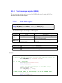
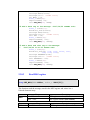
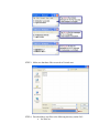
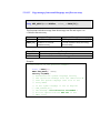
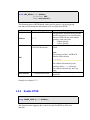
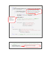
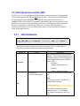
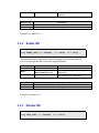
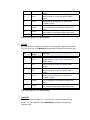
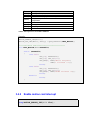
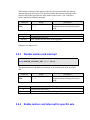
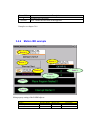
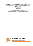
1
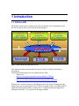
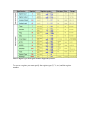
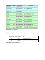
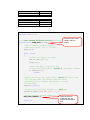
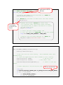
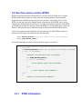
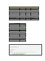
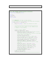
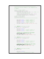
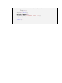
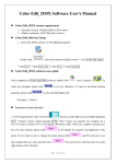
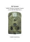
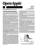
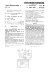
EzCore API User Manual (Version 4.3) Warranty All products manufactured by ICPDAS Inc. are warranted against defective materials for a period of one year from the date of delivery to the original purchaser. Warning ICPDAS Inc. assumes no liability for damages consequent to the use of this product. ICPDAS Inc. reserves the right to change this manual at any time without notice. The information furnished by ICPDAS Inc. is believed to be accurate and reliable. However, no responsibility is assumed by ICPDAS Inc. for its use, or for any infringements of patents or other rights of third parties resulting from its use. Copyright Copyright 1997-2009 by ICPDAS Inc., LTD. All rights reserved worldwide. Trademark The names used for identification only maybe registered trademarks of their respective companies. License The user can use, modify and backup this software on a single machine. The user may not reproduce, transfer or distribute this software, or any copy, in whole or in part. Technical Support If you have problems about using the product, please contact ICP DAS Product Support. Email: [email protected] EzCore API 1 Introduction................................................................................................................. 4 1.1 EzCore API ......................................................................................................... 4 2 Setting the EzCore Engine .......................................................................................... 7 2.1 EzCore initialization ........................................................................................... 7 2.1.1 Hardware initialization................................................................................ 7 2.2 EzCore Engine: Start and Stop ........................................................................... 8 2.2.1 Start scan engine ......................................................................................... 8 2.2.2 Stop scan engine ......................................................................................... 8 2.3 IO and Register APIs ........................................................................................ 10 2.3.1 Digital and analog register ........................................................................ 10 2.3.2 Timer......................................................................................................... 15 2.3.3 Counter...................................................................................................... 17 2.3.4 Step ........................................................................................................... 20 2.3.5 Software M flag functions ........................................................................ 22 2.3.6 Register for standard data types................................................................ 24 2.3.7 Bit manipulation in the DB register .......................................................... 30 2.3.8 Text message register (MSG) ................................................................... 35 2.3.9 System protection with AES..................................................................... 42 3 EzCore application programming ............................................................................. 45 3.1 User thread ........................................................................................................ 45 3.1.1 Execution of a user defined thread............................................................ 45 3.1.2 Closing flag a user defined thread ............................................................ 46 3.1.3 User thread example ................................................................................. 48 3.2 Real time service routine (RTSR)..................................................................... 52 3.2.1 RTSR initialization ................................................................................... 52 3.2.2 Enable RTSR ............................................................................................ 53 3.2.3 Disable RTSR ........................................................................................... 54 3.2.4 RTSR execution time................................................................................ 54 3.2.5 RTSR example .......................................................................................... 55 3.3 Interrupt service routine (ISR) .......................................................................... 58 3.3.1 ISR initialization ....................................................................................... 58 3.3.2 Enable ISR ................................................................................................ 59 3.3.3 Disable ISR ............................................................................................... 59 3.3.4 ISR execution time.................................................................................... 60 3.3.5 ISR example.............................................................................................. 61 3.4 Motion interrupt ................................................................................................ 66 3.4.1 Motion card ISR initialization .................................................................. 66 3.4.2 Enable motion card interrupt .................................................................... 69 3.4.3 Disable motion card interrupt ................................................................... 70 3.4.4 Enable motion card interrupt for specific axis.......................................... 70 3.4.5 Disable motion card interrupt for specific axis......................................... 71 3.4.6 Motion ISR example ................................................................................. 72 4 Appendix................................................................................................................... 79 4.1 Error table ......................................................................................................... 79 1 Introduction 1.1 EzCore API The EzProg-I framework is running on the EzCore platform. The relationship between the EzCore and its APIs is shown on the following figure: Register Digital I/O Analog I/O S,M,T,C,D,B, W,DW,F,DB,MSG IN_Xa(Xno) OUT_Y(Yno,on/off) IN_AI(AIno) OUT_AO(AOno,Vo t) EzCore Interrupt RTSR USER Figure 1: APIs and threads supported by EzCore This manual introduces and describes the EzCore APIs provided for the EzProg-I programmer. Currently the following devices are supported by the APIs: − I8000 series http://www.icpdas.com/products/motion/EzProg-I_i8K.htm − Motion control modules http://www.icpdas.com/products/motion/motion_I8K_Guide.htm EzProg1 has a section of memory called Register where bit, integer, floating point and string values can be stored and accessed. The EzCore engine scans every millisecond all digital and analog input modules to update the X, AI registers and writes digital and analog data from the Y, AO registers to the output modules. Table 1: Register types and register numbers supported by EzCore To access a register you must specify the register type (X, Y, etc.) and the register number. Table 2: APIs to access the registers The following registers are already reserved for multi-language and virtual keyboard support: Register Type Register Number Note D 8000 Multilanguage selection M 16000 Enabling or disabling virtual keyboard support for the ColorEdit Control Table 3: Registers reserved for the EzCore 2 Setting the EzCore Engine 2.1 EzCore initialization 2.1.1 Hardware initialization long DEVICE_INITIAL(WORD Para1, WORD Para2, WORD RunMode); This function loads the program, reads and writes IO data. Parameter Para1 0: 1: Para2 Range OUTPUT_Clear OUTPUT_Now 0: IO_MODE_Direct 1 : IO_MODE_AutoScan RunMode 1 : Return Value 0 Nonzero RUN_PRG_MODE Description Sets all DO and AO to zero After loading the program the default initial values are written to the DO and AO DIO and AIO are directly accessed The DIO and AIO are scanned at fixed time intervals Run program mode Description Execution was successful Error: consult the error table at the appendix Example: long ret; ret=DEVICE_INITIAL(OUTPUT_Now,0,RUN_PRG_MODE); if (ret == _NO_ERROR) { ret=SCAN_ENGINE_START(); if (ret == _NO_ERROR) { SET_M(200,true); //System initial ok } else MessageBox( TEXT("Starting the EzCore engine TEXT("EzCore Engine"), failed!"), MB_OK|MB_ICONERROR); } else { MessageBox( TEXT("Loading device data failed") TEXT("\n Use EzConfig utility to rescan the slot modules"), TEXT("EzCore Engine"), MB_OK|MB_ICONERROR); } 2.2 EzCore Engine: Start and Stop 2.2.1 Start scan engine long SCAN_ENGINE_START(); This function starts the scanning process. Return Value 0 Nonzero Description Execution was successful Error: consult the error table at the appendix Example: See chapter 2.1.1. 2.2.2 Stop scan engine long SCAN_ENGINE_STOP(); This function stops the EzCore scan engine. Return Value 0 Nonzero Description Execution was successful Error: consult the error table at the appendix Example: See chapter 2.1.1. 2.3 IO and Register APIs EzCore provides basically three kinds of registers types: − Registers which are directly mapped to I/O ports with the EzConfig utility: These register stores data of their corresponding I/O channels. Every millisecond the input registers are updated with data of the corresponding digital and analog input channels and in the same cycle data stored in the output register are written to the output channels. − Counter, timer and step register. − Register representing c language data types (e.g. bit, Byte, integer, etc.). They can be accessed by every thread and function. The EzHMI objects make extensive use of these registers. 2.3.1 Digital and analog register Before calling an EzCore functions it is necessary to map each individual digital and analog channel to a register by using the EzConfig utility. The EzConfig utility automatically detects all the modules in the PAC device and assigns each channel to a register number of the corresponding register type. The programmer can access these register by calling the API for this register type together with the register number (see Table 2). 2.3.1.1 Writing digital output void OUT_Y( WORD DOno, bool Flag); This function writes digital output data to the digital output (Y) register. Parameter Range Local DO: 0 to 777 FRNet DO: 1000 to 7777 DOno Flag true false Description Digital output (Y) register number (base-8 number) Note: These numbers are octal numbers. Octal number are indicated in c with a preceding zero (e.g. 01, 02, etc.). ON or OFF 2.3.1.2 Read digital output bool GET_Ya( WORD DOno); This function reads digital output data from the digital output (Y) register. Parameter Range Local DO: 0 to 777 FRNet DO: 1000 to 7777 DOno Return Value true false 2.3.1.3 Description Digital output (Y) register number (base-8 number) Note: These numbers are octal numbers. Octal number are indicated in c with a preceding zero (e.g. 01, 02, etc.). Description Current register status: ON Current register status: OFF Read digital output (negated) bool GET_Yb( WORD DOno); This function reads the negated digital output data from the digital output (Y) register. Parameter Range Local DO: 0 to 777 FRNet DO: 1000 to 7777 DOno Return Value false true Description Digital output (Y) register number (base-8 number) Note: These numbers are octal numbers. Octal number are indicated in c with a preceding zero (e.g. 01, 02, etc.). Description Current register status: ON Current register status: OFF 2.3.1.4 Read digital input bool IN_Xa( WORD DIno); This function reads digital input data from the digital input (X) register. Parameter Range Local DI: 0 to 777 FRNet DI: 1000 to 7777 DIno Return Value true false 2.3.1.5 Description Digital input (X) register number (base-8 number) Note: These numbers are octal numbers. Octal number are indicated in c with a preceding zero (e.g. 01, 02, etc.). Description Current register status: ON Current register status: OFF Read digital input (negated) bool IN_Xb( WORD DIno); This function returns the negated digital input data from the digital input (X) register. Parameter Range Local DI: 0 to 777 FRNet DI: 1000 to 7777 DIno Return Value false true Description Digital input (X) register number (base-8 number) Note: these numbers are octal numbers. Octal number are indicated in c with a preceding zero(e.g. 01, 02, etc.) Description Current register status: ON Current register status: OFF 2.3.1.6 Write analog output void OUT_AO( WORD AOno, float Vout); This function writes analog output data to the analog output (AO) register. Parameter Range AOno Local AO: 0 to 511 Vout 3.4E+/-38 2.3.1.7 Description Analog output (AO) register number Analog output value Read analog output float GET_AO( WORD AOno); This function reads the analog output data from the analog output (AO) register. Parameter Range AOno Local AO: 0 to 511 Return Value float value 2.3.1.8 Description Analog output (AO) register number Description Analog output value Read analog input float IN_AI( WORD AIno); This function reads the analog input data from the analog input (AI) register. Parameter Range AIno Local AI: 0 to 511 Return Value float value Description Analog input (AI) register number Description Analog input value 2.3.2 Timer 2.3.2.1 Set timer void SET_T(BYTE Tno, bool Flag, DWORD ms); This function starts and stops the timer count down. The timer counts down the value entered for the ms parameter. The timer stops once it has reached zero. In this case the Flag parameter has to be set to false to prepare the time register for the next count down. As a general rule it is always necessary to rest (Flag= false ) the time register before the timer can be started again. Parameter Range Tno 1 ~ 299 true Flag false ms 1 ~ 4,294,967,295 ms 2.3.2.2 Description Timer (T) register number Starts the timer Stops the timer count down time (milliseconds) Current timer value DWORD GET_T( BYTE Tno); This function reads the remaining count down time in milliseconds. Parameter Tno 1 ~ 299 Range Description Timer (T) register number Return Value Description 1~ timer count down value (milliseconds) 4,294,967,295 2.3.2.3 Timer status bool GET_Tb(BYTE Tno); This function checks whether the timer is active or switched off. Parameter Tno 1 ~ 299 Return Value true false 2.3.2.4 Range Description Timer (T) register number Description Current timer status: ON Current timer status: OFF Negated timer status bool GET_Tb(BYTE Tno); This function checks whether the timer is active or switched off and returns the negated result. Parameter Tno 1 ~ 299 Return Value true false Range Description Timer (T) register number Description Current timer status: OFF Current timer status: ON 2.3.3 Counter 2.3.3.1 Set counter void SET_C( WORD Cno, bool Flag, DWORD COUNT); This function starts the count down or continues to count down. The counter stops once it has reached zero. In this case the RESET_C(WORD Cno) function has to be called to prepare the counter for the next count down. Parameter COUNT Range None retain: 1 ~ 511 Retain: 512 ~ 1023 true false 1 ~ 4,294,967,295 2.3.3.2 Reset counter Cno Flag Description Counter (C) register number (volatile) Counter (C) register number (non-volatile) Start the counter Stop the counter Number from which to start the count down void RESET_C( WORD Cno); This function resets the counter so that it can be used for the next count down procedure. Parameter Cno 2.3.3.3 Range 1 ~ 511 512 ~ 1023 Current counter value bool GET_Ca(WORD Cno); Description Counter (C) register number (volatile) Counter (C) register number (non-volatile) This function reads the current count down value. Parameter Cno Range 1 ~ 511 512 ~ 1023 Return Value 0~ 4,294,967,295 2.3.3.4 Description Counter (C) register number (volatile) Counter (C) register number (non-volatile) Description Count down value (milliseconds) Counter status bool GET_Ca(WORD Cno); This function checks whether the counter is enabled or disabled. Parameter Cno Range 1 ~ 511 512 ~ 1023 Return Value true false 2.3.3.5 Description Counter (C) register number (volatile) Counter (C) register number (non-volatile) Description Current counter status: ON Current counter status: OFF Negated counter status bool GET_Cb(WORD Cno); This function checks whether the counter is enabled or disabled and returns the negated result. Parameter Cno Range 1 ~ 511 512 ~ 1023 Return Value true false Description Counter (C) register number (volatile) Counter (C) register number (non-volatile) Description Current counter status: OFF Current counter status: ON 2.3.4 Step 2.3.4.1 Set Step void SET_S( WORD Sno); This function sets the flag of the Step register to true (ON). Parameter Range Sno 1 ~ 8191 2.3.4.2 Description Step (S) register number Reset Step void RST_S( WORD Sno); This function sets the flag of the Step register to false (OFF). Parameter Range Sno 1 ~ 8191 2.3.4.3 Description Step (S) register number Read Step flag status bool GET_S( WORD Sno); This function reads the current flag status of the Step register. Parameter Range Sno 1 ~ 8191 Description Step (S) register number Return Value true false Description Current Step flag: ON Current Step flag: OFF 2.3.5 Software M flag functions 2.3.5.1 Set M flag value void SET_M( WORD Mno, bool Flag); This function sets the flag of an M register to true or false. Parameter Mno Flag Range 1 ~ 6999 8192 ~ 15999 16000 true false 2.3.5.2 Description M flag register number (volatile) M flag register number (non-volatile) Reserved for enabling and disabling the virtual keyboard of the EzHMI ColorEdit objects ON OFF Read M flag status bool GET_Ma( WORD Mno); This function reads the status of an M flag register. Parameter Mno Range 1 ~ 6999 8192 ~ 15999 16000 Return Value Description M flag register number (volatile) M flag register number (non-volatile) Reserved for enabling and disabling the virtual keyboard of the EzHMI ColorEdit objects Description true false Current M flag status : ON Current M flag status: OFF 2.3.5.3 Read negated M flag status bool GET_Mb(WORD Mno); This function returns the negated status of an M flag register. Parameter Mno Range 1 ~ 6999 8192 ~ 15999 16000 Return Value false true Description M flag register number (volatile) M flag register number (non-volatile) Reserved for enabling and disabling the virtual keyboard of the EzHMI ColorEdit objects Description Current M flag status : ON Current M flag status: OFF 2.3.6 Register for standard data types 2.3.6.1 D register type (long integer) Each D register consists of four bytes and stores values in the range from -2,147,483,648 to 2,147,483,647. 2.3.6.1.1 Write D register void SET_D(WORD Dno, long Val); This function assigns a value to the D register. Parameter Dno Val Range 1 ~ 1023 1024 ~ 1999 8000 8100 -2,147,483,648 to 2,147,483,647 Description D register number (volatile) D register number (non-volatile) Reserved for multi-language setting FRAM W/R ERROR 2.3.6.1.2 Read D register long GET_D(WORD DNo); This function returns the value stored in the D register. Parameter Dno Range 1 ~ 1023 1024 ~ 1999 8000 8100 Return Value -2,147,483,648 Description D register number (volatile) D register number (non-volatile) Reserved for multi-language setting FRAM W/R ERROR Description D register value to 2,147,483,647 2.3.6.2 B register type (unsigned char) The B register has a size of one byte and stores positive values in the range from 0 to 255. 2.3.6.2.1 Write B register void SET_B(WORD Bno, BYTE data); This function assigns a value to the B register. Parameter Bno data Range 1 ~ 699 1024 ~ 2047 0 to 255 Description B register number (volatile) B register number (non-volatile) 2.3.6.2.2 Read B register BYTE GET_B(WORD Bno); This function returns the value stored in the B register. Parameter Bno Range 1 ~ 699 1024 ~ 2047 Return Value 0 to 255 Description B register number (volatile) B register number (non-volatile) Description B register value 2.3.6.3 W register type (unsigned short) The W register has a size of two bytes and stores positive values in the range from 0 to 65535. 2.3.6.3.1 Write W register void SET_W(WORD Wno, WORD data); This function assigns a positive value to the W register. Parameter Wno data Range 1 ~ 1023 1024 ~ 1999 0 to 65535 Description W register number (volatile) W register number (non-volatile) 2.3.6.3.2 Read W register WORD GET_W(WORD Wno); This function returns the value stored in the W register. Parameter Wno Range 1 ~ 1023 1024 ~ 1999 Return Value 0 to 65535 Description W register number (volatile) W register number (non-volatile) Description W register value 2.3.6.4 DW register type (unsigned long) The DW register has a size of four bytes and stores positive values in the range from 0 to 4,294,967,295. 2.3.6.4.1 Write DW register void SET_DW(WORD DWno, DWORD data); This function assigns a positive value to the DW register. Parameter DWno data Range 1 ~ 4095 4096 ~ 8191 0 to 4,294,967,295 Description DW register number (volatile) DW register number (non-volatile) 2.3.6.4.2 Read DW register DWORD GET_DW(WORD DWno); This function returns the value stored in the DW register. Parameter DWno Range 1 ~ 4095 4096 ~ 8191 Return Value 0 to 4,294,967,295 Description DW register number (volatile) DW register number (non-volatile) Description DW register value 2.3.6.5 F register type (float) The F register type has a size of four bytes and stores float values in the range of 3.4E +/- 38. 2.3.6.5.1 Write F register void SET_F(WORD Fno, float data); This function assigns a float value to an F register. Parameter Fno data Range 1 ~ 1899 2048 ~ 3999 3.4E +/- 38 Description F register number (volatile) F register number (non-volatile) 2.3.6.5.2 Read F register float GET_F(WORD Fno); This function returns the float value stored in an F register. Parameter Fno Range 1 ~ 1899 2048 ~ 3999 Return Value 3.4E +/- 38 Description F register number (volatile) F register number (non-volatile) Description F register value 2.3.7 Bit manipulation in the DB register The DB register type has a size of 16 bytes (128 bits). EzCore provides several functions to access or manipulate specific bits in the register. 2.3.7.1 Set a single bit void DB_SETx1(BYTE DBno, BYTE Num, bool data); This function sets one bit at the specified position of the DB register. Parameter DBno 1 ~ 49 Num 0 ~ 127 data 0 or 1 2.3.7.2 Range Description DB register number Bit position Read a single bit bool DB_GETx1(BYTE DBno, BYTE Num); This function reads one bit from the specified position of the DB register. Parameter DBno 1 ~ 49 Num 0 ~ 127 Return Value 1 Range Description DB register number Bit position Description Bit is set 0 2.3.7.3 Bit is not set Set an array of 8 bits void DB_SETx8(BYTE DBno, BYTE Num, BYTE data); This function writes one byte at the specified position of the DB register. Parameter DBno 1 ~ 49 Num 0 ~ 15 data 0 ~ 255 2.3.7.4 Range Description DB register number Byte position Byte value Read an array of 8 bits BYTE DB_GETx8(BYTE DBno, BYTE Num); This function reads one byte from the specified position of the DB register. Parameter DBno 1 ~ 49 Num 0 ~ 15 Return Value 0 ~ 255 2.3.7.5 Range Description DB register number Byte position Description Byte value Set an array of 16 bits (WORD) void DB_SETx16(BYTE DBno, BYTE Num, WORD data); This function writes two bytes at the specified position of the DB register. Parameter Range DBno 1 ~ 49 Num 0~7 data 0 ~ 65,535 2.3.7.6 Description DB register number WORD position WORD value Read an array of 16 bits (WORD) WORD DB_GETx16(BYTE DBno, BYTE Num); This function reads two bytes from the specified position of the DB register. Parameter DBno 1 ~ 49 Num 0~7 Return Value 0 ~ 65,535 2.3.7.7 Range Description DB register number WORD position Description WORD value Set an array of 32 bits (DWORD) void DB_SETx32(BYTE DBno, BYTE Num, DWORD data); This function writes four bytes at the specified position of the DB register. Parameter Range DBno 1 ~ 49 Num 0~3 data 0 ~ 4,294,967,295 Description DB register number DWORD position DWORD value 2.3.7.8 Read an array of 32 bits (DWORD) DWORD DB_GETx32(BYTE DBno, BYTE Num); This function reads four bytes from the specified position of the DB register. Parameter DBno 1 ~ 49 Num 0~3 Range Return Value 0~ DWORD value 4,294,967,295 2.3.7.9 Description DB register number DWORD position Description Logical left shift void DB_SL(BYTE DBno, BYTE Shift); This function shifts the bits of a DB register a specified number of positions to the left. Parameter DBno 1 ~ 49 Shift 1 ~ 128 Range Description DB register number The number of positions to shift to the left 2.3.7.10 Logical right shift void DB_SR(BYTE DBno, BYTE Shift) This function shifts the bits of a DB register a specified number of positions to the right. Parameter DBno 1 ~ 49 Shift 1 ~ 128 Range Description DB register number The number of position to shift to the right 2.3.8 Text message register (MSG) The text message register can be accessed via EzHMI objects or by using the EzCore functions described in this chapter. 2.3.8.1 Write MSG register long SET_MSG(WORD MSGno, wchar_t UMSG[30]); This function assigns a text string to a MSG register. Parameter MSGno Range 1 ~ 244 245 ~ 249 UMSG[30] Pointer to a Unicode characters array Return Value 0 Nonzero Description MSG register number (non-volatile) MSG register number (non-volatile) reserved for passwords. Unicode character array storing the Message Description Execution was successful Error: consult the error table at the appendix Example: //1.Write a UNICODE character string to MSG register number 100 RET= SET_MSG(100, L"ICPDAS Info"); //2. or use a CStringW CStringW CS= L"ICPDAS Info"; wchar_t UMSG[30]; //Copy the CStringW message to the UMSG array: swprintf(UMSG, CS); RET= SET_MSG(101, UMSG); //3.Add a time label to the message: "10:20:55 ICPDAS Info" CEzLIB EzLIB; wchar_t tcTime[15]; EzLIB.Get_Time(tcTime); CStringW HMSm(tcTime); CStringW CS= L" ICPDAS Info"; CS= HMSm + CS; wchar_t UMSG[30]; swprintf(UMSG, CS); ret= SET_MSG(102, UMSG); //4.Add a date tag to the message: "2007/04/26 ICPDAS Info" wchar_t tcDate[15]; EzLIB.Get_Date(tcDate); CStringW YMD(tcDate); CStringW CS1= L" ICPDAS Info"; CS1= YMD + CS1; wchar_t UMSG1[30]; swprintf(UMSG1, CS1); ret= SET_MSG(103, UMSG1); //5.Add a date and time tag to the message: // "2007/04/26 10:20:55 ICPDAS Info" wchar_t tcDT[30]; EzLIB.Get_DT(tcDT, true, true, false, true, true, true, true); CStringW YMWDHMSm(tcDT); CStringW CS2= L" ICPDAS Info"; CS2= YMWDHMSm + CS2; wchar_t UMSG2[30]; swprintf(UMSG2, CS2); ret= SET_MSG(104, UMSG2); 2.3.8.2 Read MSG register long GET_MSG(WORD MSGno, wchar_t UMSG[30]); This function reads the message stored in the MSG register and writes it to a Unicode character array. Parameter DWno Parameter MSGno Range 1 ~ 4095 4096 ~ 8191 Range 1 ~ 244 Description DW register number (volatile) DW register number (non-volatile) Description MSG register number (non-volatile) 245 ~ 249 UMSG[30] Pointer to a Unicode characters array Return Value 0 Nonzero MSG register number (non-volatile) reserved for passwords. Unicode character array receiving the text string Description Execution was successful Error: consult the error table at the appendix Example: wchar_t UMSG[30]; RET= GET_MSG(100, UMSG); //Copy the text from the array to a CStringW CStringW CS(UMSG); 2.3.8.3 Accessing multi-language message files EzProg-I supports text messages for eight languages and provides for each language a separate text file. The messages used for the program have to be added together with a unique message identifier to the text files. Identical messages in the different language files have to use the same identifier. A message is not allowed to exceed 30 characters. The number of messages are restricted to 1000 (identifier: 0 to 999) per text file. The text files themselves can be created on the PC by using Notepad. The messages have to be saved as UNICODE text files. The text file names are predefined (ML0.txt ~ML7.txt) and must be strictly adhered to. The ML0.txt file contains the messages of the first system language, the ML1.txt file represents the second system language, etc. The text files have to be downloaded to the following PAC directory: − for WinCon: “\CompactFlash\EzProg-I\EzHMI\ML” − for MPac: “\System_Disk\EzProg-I\EzHMI\ML” The D register number 8000 is reserved for language setting. It enables the user to switch the language setting during runtime. The first language in the list is represented by the value 0 in the D 8000 register and the eighth language by the value 7. Example: The following system support three language settings: English, Spanish, Chinese STEP 1: Assign a language index to each language: English – Language 0 Æ ML0.txt Spanish – Language 1 Æ ML1.txt Chinese – Language 2 Æ ML2.txt The language switching during runtime is done by choosing the index of the corresponding language. STEP 2: Enter the following messages in the three message text files: English Æ ML0.txt: 0: Initialization succeeded. 1: Login succeeded. Spanish Æ ML1.txt: 0: Inicialización del éxito. 1: Login de éxito. Chinese Æ ML2.txt 0:系統初始化 OK !! 1:使用者登入成功 !! STEP 3: Make sure that these files are saved as Unicode text. STEP 4: Download these text files to the following directory on the PAC: for WinCon: “\CompactFlash\EzProg-I\EzHMI\ML” for MPac: “\System_Disk\EzProg-I\EzHMI\ML” 2.3.8.3.1 Copy message from a multi-language text file to a MSG register long SET_MSGF(WORD MSGno, WORD MSGFno); This function reads the message from the message text file and copies it to a MSG register. Parameter MSGno 1 ~ 249 0 ~ 999 MSGFno Return Value 0 Nonzero Range Description MSG register number (non-volatile) Message identifier in the message text file Description Execution was successful Error: consult the error table at the appendix Example: // continuation of the previous example: RET= SET_MSGF(100, 0); // Determines the system language setting // and copies the message with the identifier 0 // from the system language text file to the // MSG register number 100. // // // // // If the sytem language is set to English [SET_D(8000,0);] the message "Initialization succeeded." will be copied from the ML0.txt to the MSG register number 100. 2.3.8.3.2 Copy message from a multi-language text file to an array long GET_MSGF(WORD MSGFno, wchar_t UMSG[30]); This function reads the message from the message text file and copies it to a Unicode character array. Parameter MSGno Range 1 ~ 249 UMSG[30] Pointer to a Unicode characters array Return Value 0 Nonzero Description MSG register number (non-volatile) Unicode character array receiving the text string Description Execution was successful Error: consult the error table at the appendix Example: // continuation of the previous example: wchar_t UMSG[30]; RET= GET_MSGF(0, UMSG); CString CS(UMSG); // Determines the system language setting // and copies the message with the identifier 0 // from the system language text file to the // array UMSG. // // // // // If the sytem language is set to English [SET_D(8000,0);] the message "Initialization succeeded." will be copied from the ML0.txt to the UMSG array. 2.3.9 System protection with AES EzCore provides functions which allows the system developer to protect its software from illegal use. The functions make use of the Advanced Encryption Standard (AES). To generate a registration key for the end user the program developer has to specify a random 16 character product key. The encryption engine of the EzConfig utility generates a registration key by using the hardware serial number of the PAC and the product key. The product key is only known to the system developer and should not be disclosed. PAC hardware serial number Product Key (only known to the system developer) AES encryption machine Registration Key (for the end customer) 2.3.9.1 Read registration key long REGISTRY_KEY(wchar_t REG[20]); This function reads the registration key entered by the user (for example via an EzHMI ColorEdit box). Parameter Range 1) pointer to an Unicode character array which contains a 16 character REG[20] registration key 2) L"MSG0" L"MSG1" Description 16 character registration key provided by the program distributor. EzConfig/Edit/EncryptÆRegistrycodeGenerator The register name and number which contains the registration key string. L"MSG249" Return Value 0 Nonzero For example: 1) If the registration key is stored in the MSG register number 1 then the following string has to be used as parameter: L"MSG1" Description Execution was successful Error: consult the error table at the appendix Example: REGISTRY_KEY(L"05386f8e9a7b6fa7"); REGISTRY_KEY(L"MSG249"); 2.3.9.2 Read registration key from AES text file long REGISTRY_FILE(); This function reads the registration key from the AES.txt file located at the following PAC directory: for WinCon: “\CompactFlash\EzProg-I\ EzConfig” for MPac: “\System_Disk\EzProg-I\EzConfig” Return Value 0 Nonzero Description Execution was successful Error: consult the error table at the appendix Example: REGISTRY_FILE(); 2.3.9.3 Registration key validation long CHECK_KEY(wchar_t AES_KEY[20]); This function uses the registration key entered by the user (for example via an EzHMI ColorEdit box) to calculate the developer product key and compares this key with the valid product key (AES_KEY). If both are identical the function returns true. Parameter Range 1) pointer to an Unicode character array which AES_KEY[20] contains a 16 character product key Return Value 0 Nonzero Description The real product key. This key should not be revealed to the end user. EzConfig/Edit/EncryptÆ Key-code Input Description The registration key is valid Error: consult the error table at the appendix Example: long RET= CHECK_KEY(L"1234567812345678"); 3 EzCore application programming 3.1 User thread The user thread allows the programmer to write low priority code like updating the user interface or other none time critical operation. Eight user threads (0 to 7) can be used simultaneously each with a different priority. The thread priority is set by assigning a number (0 to 7) when a new thread is being called. It is not possible to run two different threads with identical priority at the same time. The first thread has to be terminated before a second thread with the same priority can be created. The priority level decreases with increasing thread number. Thread number 0 has the highest and thread number 7 the lowest priority. A user thread can be called anywhere in the program by calling the START_USER_THREAD function. 3.1.1 Execution of a user defined thread long START_USER_THREAD( BYTE USERno, LPTHREAD_START_ROUTINE lpStartAddress); This function creates a new thread with the specified priority and executes the assigned user defined function in this new thread. At most eight threads can be created. The EzCore does not allow two user threads with identical priority levels to run simultaneously. Therefore once a user thread with a certain priority is running it is not possible to add another user thread with the same priority to the EzCore platform. A new thread of the same priority can only be created once the existing thread has called the END_USER_THREAD function. Parameter USERno Range 0 ~7 Description At most eight threads can be created (0 to 7). The thread number indicates the threads name and its priority. It is not allowed to create two threads with the same number (priority) at the same time. 0 7 Pointer to the user defined thread function - highest priority - lowest priority 0 ~ 4 Soft Real Time 5 ~ 7 Non Real Time(MFC Class) Name of the function to be called in the thread. Note: The prototype of the CALLBACK function looks like this: lpStartAddress unsigned long USER_THREAD(void*); The callback function may have any name. The callback function must have only one void* parameter and an unsigned long return type. Return Value 0 Nonzero Description Execution was successful Error: consult the error table at the appendix Example: see chapter 3.1.3. 3.1.2 Closing flag a user defined thread long END_USER_THREAD (BYTE USERno); This function indicates to the START_USER_THREAD function that the specified user thread has finished executing. The START_USER_THREAD function can only open a new thread when the previous thread of the same number has ended with the END_USER_THREAD call. Therefore it is important to call END_USER_THREAD at the end of each user thread. Parameter USERno Range 0 ~7 Description The thread number to close Return Value 0 Nonzero Description Execution was successful Error: consult the error table at the appendix Example: see chapter 3.1.3. 3.1.3 User thread example Button 1 Label 1 Button 2 Label 2 Label 3 Main property setting of the EzHMI objects: Property Button(Up)-->Mno(On) Mno(On)-->DisableActiveX Button 1 Register number Register type 110 M 200 M Description Button click Disable/enable button Property Button(Up)-->Mno(On) Mno(On)-->DisableActiveX Button 2 Register number Register type 111 M 201 M Description Button click Disable/enable button Label 1: Loop count Property Select MSG/AI/AO/D/F D Register MSG/AI/AO/D/FnoÆLabel 1 Label 2: Time in milliseconds Property Select MSG/AI/AO/D/F MSG/AI/AO/D/FnoÆLabel D Register 10 Label 3: User thread and RTSR status Property Select MSG/AI/AO/D/F MSG Register MSG/AI/AO/D/FnoÆLabel 1 #include "EzCore.h" Function which will be //====user thread callback function=========== called in the new unsigned long USER_RUN(void *) thread. { //The D register number 1 stores //the loop counts. Set it to zero: SET_D(1,0); while (true) { //Count the number of loops: SET_D(1,GET_D(1)+1); Sleep(500); //Exit the while loop after the //"Stop User Run" button (Button 2) has been clicked: if (GET_Ma(111)) break; } //Reset the “Stop User Run” button (Button 2) event flag //to indicate that the button event has been //processed and to enable the button to create //a new event: SET_M(111,false); //Display the following message on “Label 3”: SET_MSG(1,TEXT("USER RUN STOP !!")); //Close the user thread number 0: END_USER_THREAD(0); return 0; } Inform the EzCore engine that the user thread has reached its end. Implement an RTSR //====RTSR callback function========================= function. void TSR_RUN() { //Display the number of milliseconds on “Label 2”: SET_D(2,GetTickCount()); //If “Button 1” has been clicked start the user thread if (GET_Ma(110)) { //Reset the button (Button 1) event flag //to indicate that the button event has been Click Button 1 //processed and to enable the button to create to start the user //a new event flag: thread. SET_M(110,false); // Start the user thread number and // call the function "USER_RUN" in the new thread long RET=START_USER_THREAD(0,USER_RUN); //Display the following message on “Label 3”: SET_MSG(1,TEXT("USER RUN START !!")); } } BOOL CEzDEMO4_USERDlg::OnInitDialog() { CDialog::OnInitDialog(); // Set the icon for this dialog. The framework does this automatically // when the application's main window is not a dialog SetIcon(m_hIcon, TRUE); // Set big icon SetIcon(m_hIcon, FALSE); // Set small icon CenterWindow(GetDesktopWindow()); screen // TODO: Add extra initialization here // center to the hpc EzCore initialization long ret; ret=DEVICE_INITIAL(OUTPUT_Now,IO_MODE_AutoScan,RUN_PRG_MODE); if (ret == _NO_ERROR) { ret=SCAN_ENGINE_START(); if (ret == _NO_ERROR) { SET_M(200,true); //System initial ok SET_RTSR(0,&(ptTSRFunc)TSR_RUN,1000); START_RTSR(0); Starts RTSR thread execution //Display the following message on “Label 3”: SET_MSG(1,TEXT("start RTSR OK !!")); } else MessageBox(TEXT("Start ENGINE NG \nPlease check"), TEXT("EzCore Engine"), MB_OK|MB_ICONERROR); } else { MessageBox( TEXT("Load ALL Device Data NG ") TEXT("\n Please check \n Please Rescan IO "), TEXT("EzCore Engine"), MB_OK|MB_ICONERROR); } return TRUE; // return TRUE // control unless you set the focus to a } void CEzDEMO4_USERDlg::OnClose() { // TODO: Add your message handler code here and/or call // default Stop the EzCore scan engine SCAN_ENGINE_STOP(); CDialog::OnClose(); } 3.2 Real time service routine (RTSR) RTSR are functions which are being called at a set time interval by the EzCore engine. RTSR enables the developer to create a real time and deterministic control program. Eight functions with different priority levels are provided. The priority level of each RTSR is fixed and can not be changed but the scan interval of the RTSR can be set by changing the default function call interval. To ensure deterministic behavior of the RTSR it is important to make sure that the code in the RTSR is executed within the set time scan interval. Therefore no sleep or indefinite loops are allowed inside the RTSR functions. The EzCore engine must be initialized and started before any other RTSR operation is performed. This requires the following two function calls: STEP 1: DEVICE_INITIAL(OUTPUT_Now,IO_MODE_AutoScan,RUN_PRG_MODE) STEP 2: SCAN_ENGINE_START(); The main command procedure to start the EzCore engine is as follows: long ret; ret=DEVICE_INITIAL(OUTPUT_Now,IO_MODE_AutoScan,RUN_PRG_MODE); if (ret == _NO_ERROR) { //EzCore initialization was successful ret=SCAN_ENGINE_START(); if (ret == _NO_ERROR) { //Scan engine start was successful } else { // Scan engine start FAILED!!! } else { //EzCore initialization ERROR!!! } 3.2.1 RTSR initialization void SET_RTSR(BYTE RTSRno, ptTSRFunc SRF, WORD msInterval); This function opens an RTSR thread with a specific priority, sets the triggering time interval and determines the function to be executed in the RTSR. Parameter RTSRno Range 0 ~7 Pointer to the CALLBACK function Description This parameter identifies the RTSR and specifies its priority. It is not allowed to run two RTSR with the same number (priority) at the same time. 0 - highest priority 7 - lowest priority Name of the function to be called in the RTSR. Note: The prototype of the CALLBACK function looks like this: SRS void RTSR(); msInterval 2~60000 milliseconds The callback function has got no parameter and a void return type. The callback function may have any name. RTSR cycle interval; calling interval of the RTSR Example: see chapter 3.1.3. 3.2.2 Enable RTSR long START_RTSR(BYTE RTSRno); This function starts triggering the event of the specified RTSR at fixed time intervals. Parameter RTSRno Return Value 0 Nonzero Range Description RTSR thread to start 0 ~7 Description Execution was successful Error: consult the error table at the appendix Example: see chapter 3.2.5. 3.2.3 Disable RTSR void STOP_RTSR(BYTE RTSRno); This function stops the triggering the RTSR event at fixed time intervals. The current RTSR task will continue executing its code until it returns but the RTSR task will not be called again. Parameter RTSRno Range 0 ~7 Description RTSR thread to stop Example: see chapter 3.2.5. 3.2.4 RTSR execution time long GET_RTSR_TIME(BYTE RTSRno); This function returns the execution of the specified RTSR. Parameter RTSRno Range 0 ~7 Description RTSR thread number Return Value Description Execution time in milliseconds. Example: see chapter 3.2.5. 3.2.5 RTSR example Button 1 Label 1 Label 2 Main property settings of the EzHMI projects: Property Button(Up)-->Mno(On) Button 1: Enable Interrupt Register number Register type 100 M Label 1: Time in milliseconds Property Select MSG/AI/AO/D/F D Register MSG/AI/AO/D/FnoÆLabel 1 Label 2: RTSR status Property Description Button click Select MSG/AI/AO/D/F MSG/AI/AO/D/FnoÆLabel MSG Register 1 #include "EzCore.h" Callback function running in the RTSR //====RTSR callback function========================= thread. void TSR_RUN() { //Display the number of milliseconds on Label 1 SET_D(1,GetTickCount()); //If “Button 1” has been clicked stop the RTSR if (GET_Ma(100)) Stops the triggering of { the RTSR event STOP_RTSR(0); //Reset the button (Button 1) event flag //to indicate that the button event has been //processed and to enable the button to create //a new event flag: SET_M(100,false); //Display the following message on “Label 2”: SET_MSG(1,TEXT("RTSR STOP !!")); } } BOOL CEzDEMO2_RTSRDlg::OnInitDialog() { CDialog::OnInitDialog(); // Set the icon for this dialog. The framework does this automatically // when the application's main window is not a dialog SetIcon(m_hIcon, TRUE); // Set big icon SetIcon(m_hIcon, FALSE); // Set small icon CenterWindow(GetDesktopWindow()); screen // center to the hpc // TODO: Add extra initialization here EzCore initialization long ret; ret=DEVICE_INITIAL(OUTPUT_Now,IO_MODE_AutoScan,RUN_PRG_MODE); if (ret == _NO_ERROR) Creates a RTSR thread with the highest { RTSR priority (0) and sets the scan time to ret=SCAN_ENGINE_START(); 1000 milliseconds. The TSR_RUN function if (ret == _NO_ERROR) will be called within the RTSR thread. { SET_M(200,true); //System initial ok SET_RTSR(0,&(ptTSRFunc)TSR_RUN,1000); START_RTSR(0); Starts the RTSR (number 0) triggering at the set time interval //Display the following message on “Label 2”: SET_MSG(1,TEXT("start RTSR OK !!")); } else MessageBox( TEXT("Start ENGINE NG") TEXT("\n Please check "), TEXT("EzCore Engine"), MB_OK|MB_ICONERROR); } else { MessageBox( TEXT("Load ALL Device Data NG") TEXT("\n Please check \n Please Rescan IO "), TEXT("EzCore Engine"), MB_OK|MB_ICONERROR); } return TRUE; // return TRUE unless you set the focus to a // control } void CEzDEMO2_RTSRDlg::OnClose() { // TODO: Add your message handler code here and/or call // default Stop the EzCore scan engine SCAN_ENGINE_STOP(); CDialog::OnClose(); } 3.3 Interrupt service routine (ISR) The PAC device can be equipped with eight hardware interrupt channels by plugging the I-8048 digital input module into the first slot of the PAC. The hardware interrupt has got the highest priority and immediately interrupts the execution of other tasks like for example RTSR or user thread. To guarantee a deterministic and real time behavior of the RTSR and to ensure that every interrupt is processed it is absolute necessary to make sure that the execution time of the interrupt function is very short. Thus the number of execution commands has to be low and no large loops or sleep commands are allowed inside an interrupt function. 3.3.1 ISR initialization long SET_INT(BYTE Channel, ptTSRFunc SRF, BYTE Slot); This function assigns a function to a specific interrupt service routine (ISR). In case of an interrupt this ISR executes the assigned function. Parameter Channel Range 0 ~7 Description The i-8048 module provides 8 interrupt channels. These interrupt channels have different priorities. The first channels (0) has the highest followed by channel (1), and so forth. 0 - channel 0 (highest interrupt priority) 7 Pointer to the CALLBACK function - channel 7 (lowest interrupt priority) Name of the function to be called in the ISR. Note: The prototype of the CALLBACK function looks like this: SRF void INTP_RUN(); The callback function has got no parameter and a void return type. The callback function may have any name. Slot 1 Return Value 0 Nonzero Only the first slot of the PAC is supported Description Execution was successful Error: consult the error table at the appendix Example: see chapter 3.3.5. 3.3.2 Enable ISR long START_INT(BYTE Channel, BYTE Mode, BYTE Slot); This function assigns a function to a specific interrupt service routine (ISR). In case of an interrupt this ISR executes the assigned function. Parameter Channel Range 0 ~7 Mode INTP_MODE_Rising 1 INTP_MODE_Falling 2 Slot 1 Return Value 0 Nonzero Description channel number interrupt triggering mode: falling or rising edge. Only the first slot is supported Description Execution was successful Error: consult the error table at the appendix Example: see chapter 3.3.5. 3.3.3 Disable ISR long STOP_INT(BYTE Channel, BYTE Slot); This function disables the interrupt service routine. The current ISR will continue executing its procedure to the end, but no new ISR can be called. A new interrupt signal from the specified channel will not generate an ISR event. Parameter Channel Slot Return Value 0 Nonzero Range 0 ~7 1 Description ISR channel number Only the first slot is supported Description Execution was successful Error: consult the error table at the appendix Example: see chapter 3.3.5. 3.3.4 ISR execution time long GET_INT_TIME(BYTE Channel, BYTE Slot); This function determines the ISR execution time of the specified interrupt channel. Parameter Channel Slot Return Value 0 Nonzero Range 0 ~7 1 Description ISR channel number Only the first slot is supported Description Execution was successful Error: consult the error table at the appendix Example: see chapter 3.3.5. 3.3.5 ISR example Button 1 Button 2 Label 1 Label 2 Label 3 Main property settings of the EzHMI objects: Property Button(Up)-->Mno(On) Mno(On)-->DisableActiveX Button 1: Enable Interrupt Register number Register type 120 M 130 M Description Button click Disable/enable button Property Button(Up)-->Mno(On) Mno(On)-->DisableActiveX Button 2: Disable Interrupt Register number Register type 121 M 131 M Description Button click Disable/enable button Label 1: Number of interrupts Property Select MSG/AI/AO/D/F D Register MSG/AI/AO/D/FnoÆLabel 1 Label 2: Time in milliseconds Property Select MSG/AI/AO/D/F D Register MSG/AI/AO/D/FnoÆLabel 10 Label 3: Interrupt setting Property Select MSG/AI/AO/D/F MSG Register MSG/AI/AO/D/FnoÆLabel 1 #include "EzCore.h" //Declare a callback function called by the interrupt service routine (ISR): void INTP_RUN0(); //Declare a callback function for the user thread: unsigned long USER_RUN7(void *); BOOL CEzDEMO5_InterruptDlg::OnInitDialog() { CDialog::OnInitDialog(); // Set the icon for this dialog. // The framework does this automatically // when the application's main window is not a dialog SetIcon(m_hIcon, TRUE); // Set big icon SetIcon(m_hIcon, FALSE); // Set small icon CenterWindow(GetDesktopWindow());// center to the hpc screen // TODO: Add extra initialization here long ret; ret=DEVICE_INITIAL(OUTPUT_Now,IO_MODE_AutoScan,RUN_PRG_MODE); if (ret == _NO_ERROR) { ret=SCAN_ENGINE_START(); if (ret == _NO_ERROR) { // Select language 0 as HMI language: SET_D(8000,0); SET_M(200,true); //System initial ok // Call the USER_RUN7 function in the user // thread number 7: long RET=START_USER_THREAD(7,USER_RUN7); // Display the following text on Label 3: SET_MSG(1,TEXT("start USER RUN 7 OK !!")); SET_M(131,true); //disable “Button 2” SET_M(130,false);//enable “Button 1” } else MessageBox( TEXT("Start ENGINE NG ") TEXT("\n Please check "), TEXT("EzCore Engine"), MB_OK|MB_ICONERROR); } else { MessageBox( TEXT("Load ALL Device Data NG") TEXT("\n Please check \n Please Rescan IO "), TEXT("EzCore Engine"), MB_OK|MB_ICONERROR); } return TRUE; // return TRUE unless you set the focus to a control } //====Interrupt callback function========================= void INTP_RUN0() { // Count the number of interrupts and display it on Label 1: SET_D(1,GET_D(1)+1); } //====User thread callback function=========== unsigned long USER_RUN7(void *) { long RET; SET_D(1,0); while (true) { //Display the tickcount value on Label 2: SET_D(10,GetTickCount()); //If Button 1 has been clicked enable the interrupt: if (GET_Ma(120)) { SET_D(1,0); SET_M(120,false); //reset “Button 1” click flag SET_M(130,true); //disable “Button 1” SET_M(131,false); //enable “Button 2” // Initialize the ISR of channel 0 // and assign the callback function INTP_RUN0 // to the ISR: RET=SET_INT(0,&(ptTSRFunc)INTP_RUN0); // Enable the ISR: RET=START_INT(0,INTP_MODE_Rising); // Display the following text on Label 3: SET_MSG(1,TEXT("Interrupt Enable !!")); } //If Button 2 has been if (GET_Ma(121)) { SET_M(121,false); SET_M(131,true); SET_M(130,false); clicked disable the interrupt: //reset “Button 2” click flag //disable “Button 1” //enable “Button 2” //Disable the ISR: RET=STOP_INT(0); // Display the following text on Label 3: SET_MSG(1,TEXT("Interrupt Disable !!")); } Sleep(999); } SET_M(111,false); // Display the following text on Label 3: SET_MSG(1,TEXT("USER RUN STOP !!")); SET_D(1,0); // Inform the EzCore that the user thread execution has // finished: END_USER_THREAD(7); return 0; } void CEzDEMO5_InterruptDlg::OnClose() { // TODO: Add your message handler code here and/or call default SCAN_ENGINE_STOP(); CDialog::OnClose(); } 3.4 Motion interrupt EzProg-I supports hardware interrupt from the following motion control modules: i8092F, i8094, i8094F, i8094A, i8094H. The APIs provided for setting and controlling these motion modules are described in detail in their manuals. Only motion cards in slot 1, slot 2 and slot 3 supports hardware interrupt. As described in the previous chapter it very important to ensure a short execution time in the interrupt service routine to guarantee a deterministic and real time behavior of the control program. This is being done by avoiding large loops, sleep commands and lengthy mathematical calculations. Note: The interrupt of the motion control modules all have the same priority. Therefore the ISR of the interrupt which happened first will be executed first. The interrupt priority of the motion control cards however is higher than that of the I-8048 digital input module. 3.4.1 Motion card ISR initialization long MOTION_SET_INT(BYTE Slot, WORD Axis, ptM_INTPFunc SRF); This function links a callback function (ISR) to an interrupts of a specific axis. Example: The i8094 card is a four axis motion controller. Each of its axes can generate several interrupt signals. The function MOTION_SET_INT links all the interrupt of an axis to one callback function. Inside the callback function the different interrupts can be processed. Parameter Range Slot 1 ~3 Axis AXIS_X AXIS_Y AXIS_Z AXIS_U SRF Pointer to the 0x1 0x2 0x4 0x8 Description Slot number. Only the first three slots support hardware interrupt for motion cards. Motion control axis i8092F: AXIS_X, AXIS_Y i8094/F: AXIS_X, AXIS_Y, AXIS_Z, AXIS_U i8094A/H: AXIS_X Name of the function to be called in case CALLBACK function of an interrupt. Note: The CALLBACK function must be of the following prototype: int INTP_MOTION (WORD MINTTable); It must have one WORD parameter and an int return type. Return Value 0 Nonzero Description Execution was successful Error: consult the error table at the appendix Example: see chapter 3.4.6. 3.4.1.1 ISR callback function typedef int (*ptM_INTPFunc)(WORD MINTTable); The function pointer is declared in the EzCore header file and points to a function which takes only one WORD and returns an integer. Thus the callback function must have the same number of parameter, parameter type and return-type! The callback function parameter (MINTTable) contains the interrupt factor. Each interrupt factor is represented by a specified bit position in the WORD parameter. When an interrupt happens, the bit representing the interrupt factor becomes 1. The following describes the interrupt factors supported by the motion cards of ICPDAS: 1. i-8092F, i-8092 The i8092F manual chapter 6.4 describes the supported eight interrupt factors. The first eight bits of the MINTTable parameter indicates the interrupt types. 0 Interrupt factors - 1 P>=C- 2 P<C- Bit Description Interrupt occurs once the value of the logical / real position counter is larger than or equal to that of COMP- register. Interrupt occurs once the value of logical / real 3 P<C+ 4 P>=C+ 5 C-END 6 C-STA 7 D-END position counter is smaller than that of COMPregister. Interrupt occurs once the value of logical / real position counter is smaller than that of COMP+ register. Interrupt occurs once the value of logical / real position counter is larger than or equal to that of COMP+ register. Interrupt occurs at the end of the constant speed drive or completion of Acceleration Offset Pulse output. Interrupt occurs at the start of the constant speed drive or begin of Acceleration Offset Pulse output. Interrupt occurs when the driving is finished Table 4: Interrupt factors for module i-8092F 2. i-8094/F The i8094F manual chapter 6.5 describes the supported eight interrupt factors. The first eight bits of the MINTTable parameter indicates the interrupt types. 0 Interrupt factors PULSE 1 P>=C- 2 P<C- 3 P<C+ 4 P>=C+ 5 C-END 6 C-STA 7 D-END Bit Description Interrupt occurs when pulse is up Interrupt occurs once the value of logical / real position counter is larger than or equal to that of COMP- register. Interrupt occurs once the value of logical / real position counter is smaller than that of COMPregister. Interrupt occurs once the value of logical / real position counter is smaller than that of COMP+ register. Interrupt occurs once the value of logical / real position counter is larger than or equal to that of COMP+ register. Interrupt occurs at the end of the constant speed drive or completion of Acceleration Offset Pulse output. Interrupt occurs at the start of the constant speed drive or begin of Acceleration Offset Pulse output. Interrupt occurs when the driving is finished Table 5: Interrupt factors for module i-8094F 3. i-8094A/H The i8094H manual chapter 6.3.7 describes the supported eight interrupt factors. The first eight bits of the MINTTable parameter indicates the interrupt types. Bit 0(0x01) 1(0x02) 2(0x04) 3(0x08) 4(0x10) 5(0x20) 6(0x40) 7(0x80) Description Line Scan finished Macro Program finished. User defined interrupt (RINT finished). being interrupted when execute a continuous interpolation. Reserved Axes Error Module Error Table 6: Interrupt factors for module i-8094A/H Example: MOTION_ENABLE_INT(MSlot); MOTION_SET_INT(MSlot, AXIS_X, &(ptM_INTPFunc)INTP_MOTION); //====Callback function========================= void INTP_MOTION(WORD MINTTable) { switch (MINTTable) { case 0x02: SET_D(1, MINTTable); SET_D(2, GET_D(2)+1); SET_MSG(2, TEXT("Macro Program") TEXT(" finished !!")); break; case 0x04: SET_D(1, MINTTable); SET_D(2, GET_D(2)+1); SET_MSG(2, TEXT("RINT finished !!")); break; default: break; } } 3.4.2 Enable motion card interrupt long MOTION_ENABLE_INT(BYTE Slot); The hardware interrupt of the motion card has to be activated before any motion interrupt function can be used. This function enables the hardware interrupt of the motion cards in the specified slot. Only motion cards in slot 1, slot 2 and slot 3 can be enabled for hardware interrupt. Parameter Slot Range 1 ~3 Return Value 0 Nonzero Description Slot number. Only the first three slots support hardware interrupt for motion cards. Description Execution was successful Error: consult the error table at the appendix Example: see chapter 3.4.6. 3.4.3 Disable motion card interrupt long MOTION_DISABLE_INT (BYTE Slot); This function disables the hardware interrupt of the motion cards in the specified slot. Parameter Slot 1 ~3 Return Value 0 Nonzero 3.4.4 Range Description Slot number. Only the first three slots support hardware interrupt for motion cards. Description Execution was successful Error: consult the error table at the appendix Enable motion card interrupt for specific axis long MOTION_START_INT (BYTE Slot, WORD Axis); This function enables the hardware interrupt of a specific axis of the motion card. The MOTION_ENABLE_INT function has to be called prior. Parameter Range Slot 1 ~3 Axis AXIS_X AXIS_Y AXIS_Z AXIS_U Return Value 0 Nonzero 0x1 0x2 0x4 0x8 Description Slot number. Only the first three slots support hardware interrupt for motion cards. Motion control axis i8092F: AXIS_X, AXIS_Y i8094/F: AXIS_X, AXIS_Y, AXIS_Z, AXIS_U i8094A/H: AXIS_X Description Execution was successful Error: consult the error table at the appendix Example: see chapter 3.4.6. 3.4.5 Disable motion card interrupt for specific axis long MOTION_STOP_INT (BYTE Slot, WORD Axis); This function disables the motion hardware interrupt of a specific axis. Parameter Range Slot 1 ~3 Axis AXIS_X AXIS_Y AXIS_Z AXIS_U 0x1 0x2 0x4 0x8 Description Slot number. Only the first three slots support hardware interrupt for motion cards. Motion control axis i8092F: AXIS_X, AXIS_Y i8094/F: AXIS_X, AXIS_Y, AXIS_Z, AXIS_U i8094A/H: AXIS_X Return Value 0 Nonzero Description Execution was successful Error: consult the error table at the appendix Example: see chapter 3.4.6. 3.4.6 Motion ISR example Button 0 Button 3 Button 1 Label 1 Button 2 Label 2 Interrupt count Label 3 Label 4 Main property setting of the EzHMI objects: Property Button(Up)-->Mno(On) Mno(On)-->DisableActiveX Button 0 Register number Register type 100 M 200 M Description Button click Disable/enable button Property Button(Up)-->Mno(On) Mno(On)-->DisableActiveX Button 1 Register number Register type 101 M 201 M Description Button click Disable/enable button Property Button(Up)-->Mno(On) Mno(On)-->DisableActiveX Button 2 Register number Register type 102 M 202 M Description Button click Disable/enable button Property Button(Up)-->Mno(On) Mno(On)-->DisableActiveX Button 3 Register number Register type 103 M 203 M Description Button click Disable/enable button Label 1: MINTTable Property Select MSG/AI/AO/D/F D Register MSG/AI/AO/D/FnoÆLabel 1 Label 2: Interrupt Count Property Select MSG/AI/AO/D/F D Register MSG/AI/AO/D/FnoÆLabel 2 Label 3 Property Select MSG/AI/AO/D/F MSG/AI/AO/D/FnoÆLabel MSG Register 2 Label 4 Property Select MSG/AI/AO/D/F MSG/AI/AO/D/FnoÆLabel MSG Register 1 #include "EzCore.h" #include "i8094H.h" BYTE MSlot=1; long ret; //STEP 1: Declare a motion interrupt callback function // for the i8094A(H) module: void INTP_MOTION(WORD MINTTable); //STEP 2: Declare a user thread callback function unsigned long USER_RUN7(void *); BOOL CEzDEMOA_8094A_InterruptDlg::OnInitDialog() { CDialog::OnInitDialog(); // Set the icon for this dialog. // The framework does this automatically // when the application's main window is not a dialog SetIcon(m_hIcon, TRUE); // Set big icon SetIcon(m_hIcon, FALSE); // Set small icon CenterWindow(GetDesktopWindow());// center to the hpc screen // TODO: Add extra initialization here long ret; // EzCore initialization: ret=DEVICE_INITIAL(OUTPUT_Now,IO_MODE_AutoScan,RUN_PRG_MODE); if (ret == _NO_ERROR) { ret=SCAN_ENGINE_START(); if (ret == _NO_ERROR) { SET_M(200,true); //System initial ok //disable “Button 0” //================================= ret=MOTION_ENABLE_INT(MSlot); ret+=MOTION_SET_INT(MSlot,AXIS_X, &(ptM_INTPFunc)INTP_MOTION); if (ret==0) { SET_M(200,false); //enable “Button 0” SET_M(201,true); //disable “Button 1” SET_M(202,true); //disable “Button 2” SET_M(203,true); //disable “Button 3” } else { SET_M(200,true); //disable “Button 0” SET_M(201,true); //disable “Button 1” SET_M(202,true); //disable “Button 2” SET_M(203,true); //disable “Button 3” } //Start executing the user thread number 7 long RET=START_USER_THREAD(7,USER_RUN7); //================================= SET_MSG(1,TEXT("start USER RUN 7 OK !!")); SET_MSG(2,TEXT("======================")); } else MessageBox( TEXT("Start ENGINE NG") TEXT("\n Please check "), TEXT("EzCore Engine"), MB_OK|MB_ICONERROR); } else { MessageBox( TEXT("Load ALL Device Data NG") TEXT("\n Please check \n Please Rescan IO "), TEXT("EzCore Engine"), MB_OK|MB_ICONERROR); } return TRUE; control } // return TRUE unless you set the focus to a //motion interrupt callback function implementation (i8094A(H)): void INTP_MOTION(WORD MINTTable) { switch (MINTTable) { //Check whether the macro program has finished: case 2: //second bit set (see Table 6) SET_D(1,MINTTable); SET_D(2,GET_D(2)+1); SET_MSG(2,TEXT("Macro Program finished !!")); break; // Check whether the user defined interrupt RINT // has finished: case 4: //third bit set (see Table 6) SET_D(1,MINTTable); SET_D(2,GET_D(2)+1); SET_MSG(2,TEXT("RINT finished !!")); break; default: break; } } //==== user thread callback function =========== unsigned long USER_RUN7(void *) { int i; long RET; SET_D(1,0); while (true) { //If "Button 0" has been clicked and the // initialization of the EzCore scan engine was succesful if (GET_Ma(100) && GET_Mb(200)) { SET_M(100,false); //Reset the "Button 0" event //============================================== //Download the macro "MP41" to the i8094H motion // module in slot "MSlot" //Start of macro "MP41": i8094H_MP_CREATE(MSlot, MP41); //Set the logical position of all axis to zero: i8094H_SET_LP(MSlot, AXIS_XYZU, 0); //The force the motion card to send an interrupt: //(see table 3 Bit number 2): i8094H_MP_SET_RINT(MSlot); //set the maximum velocity to 20000 PPS: i8094H_SET_MAX_V(MSlot, AXIS_XYZU, 20000); //Set all four axis to symmetric T-curve: i8094H_NORMAL_SPEED(MSlot, AXIS_XYZU, 0); //Set the speed of all axis to 2000 PPS: i8094H_SET_V(MSlot, AXIS_XYZU, 2000); //Set the accelleration of all axis to 1000 //PPS/sec: i8094H_SET_A(MSlot, AXIS_XYZU, 3000); //Set the starting velocity to 2000PPS: i8094H_SET_SV(MSlot, AXIS_XYZU, 1000); //Set the remaining offset pulses to 0: i8094H_SET_AO(MSlot, AXIS_XYZU, 0); // Call macro "MP50": i8094H_MP_CALL(MSlot, MP50); // End of macro "MP41": i8094H_MP_CLOSE(MSlot); //================================================== //=========================================== //Download the macro "MP50" to the i8094H motion // module //Start of macro "MP50": i8094H_MP_CREATE(MSlot, MP50); i8094H_MP_SET_VAR(MSlot, VAR1, 0); //VAR1 = 0。 //Move all axis 5000 pulses i8094H_FIXED_MOVE(MSlot, AXIS_XYZU, 5000); i8094H_MP_STOP_WAIT(MSlot, AXIS_XYZU); // End of macro "MP50": i8094H_MP_CLOSE(MSlot); //=============================================== SET_M(200,true); //disable “Button 0” SET_M(201,false); //enable “Button 1” SET_M(202,true); //disable “Button 2” SET_M(203,false); //enable “Button 3” SET_MSG(1,TEXT("Interrupt Setting Ok !!")); } //If "Button 1" has been clicked if (GET_Ma(101) && GET_Ma(200)) { SET_M(101,false); SET_M(201,true); //disable “Button 1” SET_M(202,false); //enable “Button 2” //Active all interrupt for the x-axis: MOTION_START_INT(MSlot,AXIS_X); SET_MSG(1,TEXT("Interrupt Started !!")); } //If "Button 2" has been clicked if (GET_Ma(102) && GET_Ma(200)) { SET_M(102,false); SET_M(202,true); //disable “Button 2” SET_M(201,false); //enable “Button 1” //Deactive all interrupt for the x-axis: MOTION_STOP_INT(MSlot,AXIS_X); SET_MSG(1,TEXT("Interrupt Stop !!")); } //If "Button 3" has been clicked if (GET_Ma(103)) { SET_M(103,false); //Execute the downloaded macro “MP41” i8094H_MP_CALL(MSlot, MP41); } Sleep(99); } SET_M(111,false); END_USER_THREAD(7); SET_MSG(1,TEXT("USER RUN STOP !!")); SET_D(1,0); return 0; } 4 Appendix 4.1 Error table #define _NO_ERROR #define _EXEC_ERROR #define _OPENFILE_ERROR #define _SETUP_ERROR #define _FRAM_INIT_ERROR #define _REGISTER_ERROR #define _NONE_MAOS_ERROR 0 -1 -2 -3 -4 -5 -6 #define _INCORECT_RUN_MODE -7 #define _DIVIDE_ZERO_ERROR -10 #define _SET_Interrupt_ERROR -20 #define I8048_ERROR_NO_MODULE #define I8048_ERROR_OPEN_DEVICE #define I8048_ERROR_INVALID_PARAMETER #define I8048_ERROR_INVALID_HANDLE #define I8048_ERROR_CALL_IOCTL #define I8048_ERROR_GET_IST_EVENT -31 -32 -33 -34 -35 -36 #define _IN_USE_ERROR #define _NO_USE_ERROR #define _OUT_OF_RANGE_ERROR -50 -51 -52 #define _AES_NOT_SETKEY_ERROR #define _AES_CHECK_ERROR -80 -81 #define _CREATE_THREAD_ERROR -90 #define _INOUT_ERROR -100 #define _STP_PARAMETER_ERROR -150 #define _SYSTEM_VERSION_ERROR #define _DEVICE_CHECK_ERROR #define _DEVICE_NOT_INIT #define _DEVICE_NOT_WinCon -200 -201 -202 -203 #define _AES_REGCODE_LENTH_ERROR #define _AES_REGMSG_NO_ERROR -250 -251 // File is not open: #define _FILE_NOT_OPEN // Read from file error: #define _READ_FILE_ERROR // Write to file error: #define _WRITE_FILE_ERROR -300 -310 -320 #define _ETHERNET_CONNECTION_ERROR 1 #define _ALREADY_RUN_WARNING 10 #define _BATTERY1_LEVEL_WARNING 21 #define _BATTERY2_LEVEL_WARNING 22 //for i8094H/A #define _I8094H_TIMEOUT_ERROR 50 //for i8092/F i8094/F i8094H/A #define _MOTION_NO_REG_ERROR 51 //for i8094/F #define _MOTION_OPENCONFIG_ERROR 52 //for i8092/F i8094/F i8094H/A #define _NON_MOTION_ERROR #define _MOTION_INTP_ALREADY_RUN 53 54 #define _SYSTEM_NOT_READY 100