1
Circuit Description--7A1817A18N
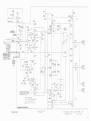
With a 1X probe (or no probe) connected t o the input
connector, 0 6 2 0 is turned off. The deflection factor readout i s determined by the VOLTS!DIV switch position. With
a 10X probe connected, the bias on 0 6 2 0 will allow 100
microamperes of collector current to flow. 1-his increases
the deflection factor readout by a factor of 10.
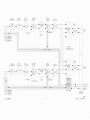
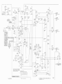
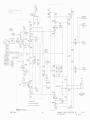
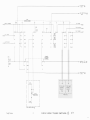
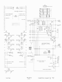
The IDENTIFY button (S13 or 523 on Diagram I ) does
two things when pressed :
I.It causes the trace representing the appropriate
channel of the 7A18 to move about 0.3 division (see the
discussion on the Channel 1 or Channel 2 Input Amplifier).
2. Forward biases CR621 and Q620 t o result in a
sufficient amount of collector current which, when added
t o the column current output, replaces the deflection factor
readout with the word "IDENTIFY".
These two actions aid in identifying the 7A18 trace
when multiple traces are displayed. When the IDENTIFY
button i s released, the deflection factor readout and trace
position are restored.
For further information on the operation of the readout
system, see the oscilloscope instruction manual.
7A18