1
TEKTRONIX
7D15
UNIVERSAL
COUNTER/TIMER
INSTRUCTION
Tektronix, Inc .
P .O . Box 500
Beaverton, Oregon
070-1433-00
97077
MANUAL
Serial Number
First Printing SEP 1974
WARRANTY
All TEKTRONIX instruments are warranted against
defective materials and workmanship for one year .
Any questions with respect to the warranty should
betaken up with yourTEKTRONIX Field Engineeror
representative .
All requests for repairs and- replacement parts
should be directed to the TEKTRONIX Field Office
or representative in your area . This will assure you
the fastest possible service. Please me ede the
instrument Type Number or Part Number and Seriai
Number with all requests for parts or service .
Specifications and price change priviiege~:, reserved .
1974 by Tektronix, Inc ., Beaverton-,
Copyright
Oregon . Printed in the United States of America. All
rights reserved . Contents of this publication may not
be reproduced in any form without permission of
Tektronix, Inc.
U .S .A . and foreign TEKTRONIX products covered
by U .S . and foreign patents and/or patents pending.
TEKTRONIX is a registered trademark of Tektronix,
Inc .
TABLE OF CONTENTS
SECTION 1
SECTION 2
SPECIFICATION
Page
Introduction
Electrical Characteristics
Environmental Characteristics
Physical Characteristics
1-1
1-1
1-7
1-7
OPERATING INSTRUCTIONS
Installation
Front Panel Controls and Connectors
Modes of Operation
Operation and Checkout
SECTION 3
CIRCUIT DESCRIPTION
Introduction
Block Diagram Description
General
Input
Clock
Gate
Counters and Readout
Reset
Trigger Input Amplifiers
Time Base
Arm Inputs
Reset Circuitry
Readout Theory
General
CH 1 Column and Row Data
CH 2 Column and Row Data
Overflow
-5 V Supply
SECTION 4
ELECTRICAL PARTS LIST
Abbreviations and Symbols
SECTION 7
DIAGRAMS AND CIRCUIT BOARD ILLUSTRATIONS
Symbols and Reference Designators
SECTION 8
4-1
4-1
4-1
4-3
4-4
4-4
CALIBRATION
Introduction
Test Equipment Required
Calibration Procedure
Index to Calibration Procedure
SECTION 6
3-1
3-1
3-1
3-1
3-1
3-2
3-7
3-7
3-8
3-8
3-9
3-9
3-10
3-10
3-10
3-12
3-13
3-14
MAINTENANCE
Introduction
Preventive Maintenance
Troubleshooting
Corrective Maintenance
Component Replacement
Recalibration After Repair
SECTION 5
2-1
2-2
2-7
2-10
MECHANICAL PARTS LIST
CHANGE INFORMATION
5-1
5-1
5-4
5-5
Fig. 1-1 . 71315 Universal Counter/Timer .
Section 1-71315
SPECIFICATIONS
Introduction
The 71315 is a digital counter plug-in designed for use with all readout-equipped 7000-Series Oscilloscope mainframes .
It will function in any plug-in compartment ; however, in the vertical compartment, a selectable display is internally connected to the oscilloscope . When used in the horizontal compartment, mainframe triggers are available to the 71315.
The 71315 has eight modes of operation : Frequency-DC to 225 MHz direct, Frequency Ratio-0 to 10 5 :1, Period10 ns to 105 s, Period Averaging- 10 ps resolution, TIM- 10 ns to 105 s, TIM Averaging-1 ns accuracy, Totalize-1 to 10 8
events, Manual Stop Watch-to 10 5 s.
The electrical specifications listed in the Performance Requirement column are valid over the stated environmental range
for instruments calibrated at an ambient temperature of +20° C to +30° C and after a five minute warmup unless otherwise
noted . The electrical specifications listed in the Supplemental Information column indicate typical instrument operation and
is not intended to be construed as a requirement for proper instrument operation . ,
TABLE 1-1
ELECTRICAL CHARACTERISTICS
Performance Requirement
Characteristics
MEASUREMENT MODES
Frequency Mode
Range
DC to 225 megahertz
Resolution
0.1 hertz minimum
1 Accuracy
Efreq (hertz) = t TB X Fi n t 1/T
1
Efreq (%) = 100% ~+ TB ± T X Fin
Period Mode
Range
10 nanoseconds to 10 5 seconds with averaging times of X1 to X1000 in decade
steps.
Resolution
10 picoseconds maximum .
1 Accuracy
Eper (sec) = t TB X Pi n ±
Eper (%) = 100%
Time Interval Mode
I±
TB +
1 X 10 s f K f Pc k
M
± 1 X 10 -9 t K f P ck
Pi n X M
Range
6 nanoseconds to 10 5 seconds with averaging times of X1 to X1000.
Resolution
0 .1 nanosecond usable .
1 Accuracy (nominal)
ETI (sec) = TB X Pi n ± (P ck/VM) ± 10-9 t K
-s
±K
ck/JM .) + 10
(P
t
ETI (%) = 100% f TB
Pin
The complete expression for Time Interval averaging depends on signal to noise
ratio and statistical distribution factors.
1
information .
Refer to Figs . 1- 2 through 1-7 at the rear of this section for additional accuracy
Specifications-7D15
TABLE 1-1 (cont)
Performance Requirement
Characteristics
Frequency Ratio
CH B/EXT clock
Range
10 -7 to 10 4
Totalize, CH B :
Range
0 to 10 8 counts
(Manual ON-OFF control or electrical control from CH A.)
Manual Stop Watch
Range
0 to 10 5 seconds
NOTE
Formulas given where T8 (dec %) is the time base accuracy; Pin is the period or time interval of the unknown
signal (whichever is applicable); M is the number of averages taken; Pck is the measurement clock period, T is the
gate time, Fin is the frequency of the unknown signal, Enpk is equal to the peak noise amplitude at the input to
the counter gate circuit, dvldt is the signal slope at the input to the gate; K is equal to 2Enpkl dvldt.
Characteristics
Performance Requirements
Supplemental Information
NPUT SIGNALS CH A & B
Frequency Range (CH B only)
DC Coupled
DC to 225 megahertz
AC Coupled
5 hertz to 225 megahertz
Sensitivity
CH A & B Inputs
100 millivolts peak-to-peak
TRIG SOURCE
0.5 divisions of vertical deflection derated
at higher frequencies .
Input Resistance and
Capacitance
Approximately 1 megohm, 22 picofarads
Minimum Pulse Width
5 nanoseconds
Minimum gate "OFF" time
Between Samples During
TIM Averaging Operation
10 nanoseconds
Maximum Input Voltage
200 volts DC linearly derated to 20 volts
at 200 megahertz
E max = 20 + 180 (1 - Fin(MHz)/200
Specifications-7D15
TABLE 1-1 (cont)
Characteristics
Minimum Signal Period in
"PER" Mode
Performance Requirements
10 nanoseconds
Minimum CH A Input Pulse
Width in "FREQ B-CH A
Gate" Mode
10 nanoseconds
Triggering
Preset Position
Automatically triggers at 0 volts
Level Control
Range : (CH A and CH B)
.1 V, ±500 millivolts ; 1 V, f5 volts; 10 V,
±50 volts
Range : TRIG SOURCE
Approximately ±2 .5 divisions
Arming Inputs
Input R and C
Approximately 10 kilohm, 20 picofarads
Lead Time for Pulse to
become effective
5 nanoseconds
Lead Time to Negate
effect of "ARM"
5 nanoseconds
Minimum rise and fall rate
dv/dt > 10 Volts per microsecond
Sensitivity A ARM
A logical "1" occurs with either no signal
applied or with +0 .5 volt or greater . A
logical "0" occurs with less than +0 .2 volt
@ I sink < 0.2 milliampere
B ARM
Logic "1" < 0.2 volt or no signal applied
Logic "0" > +0 .5 volt
Maximum Operating Voltage
+10 volts to -5 volts
Maximum Input Voltage
±15 volts
External Clock In
Input Requirements
Supplemental Information
Internal switch selectable
Minimum Amplitude
0 .8 volt peak-to-peak sine wave or pulse
with 30% to 70% duty cycle
Coupling
AC
Specifications-7D15
TABLE 1-1 (cont)
Characteristics
Performance Requirements
Maximum Input Voltage
±50 volts DC, 20 volts peak-to-peak
Frequency Range
1 megahertz ±5% ; Phase Lock Operational . 10 nanoseconds, 100 nanoseconds
clock available .
Supplemental Information
20 hertz to 5 megahertz; Phase Lock
Nonoperational .
RESET-Front Panel
Reset initializes the instrument . All
counters are affected, including averaging
circuits .
Input R and C
Approximately 10 kilohms, 30 picofarads
Input Requirements
Amplitude
Logic "1" + 2 volts or greater
Logic "0" + 0.5 volt or less
Pulse Width
> 500 nanoseconds
Maximum Operating
Input Voltage
+10 volts to -10 volts
Rise and Falltime
100 nanoseconds or less
Maximum Input Voltage
± 15 volts
Reset (located on Rear
Interface B13)
Negative-going transition TTL compatible
pulse
Rise and Falltime
< 100 nanoseconds
Width
> 500 nanoseconds
Hold Signal (located on
Rear Interface B22)
TTL compatible, negative-logic signal
Rise and Falltime
< 200 nanoseconds
Propagation Delay for
Signal to become
effective or ineffective
< 100 nanoseconds
Specifications-71315
TABLE 1-1 (cont)
Characteristics
Performance Requirements
Supplemental Information
INTERNAL TIME BASE
Crystal Oscillator
Frequency
5 megahertz
Accuracy
0° C to +50° C
Long Term Drift
Within 0.5 part per million
1 part or less in 10 7 per month
OUTPUT SIGNALS
Monitor Signals
Clock Out
Logic "1" _ +0 .5 volt ±10% into 50 ohms
Zout 430 ohms
Logic "0" < 0 volt into 50 ohms . TTL
compatible without 50 ohm load (1 .6
milliamper current capacity)
A and B Trigger Level
Zout = 1 kilohm
Vout -±0.5 volt into 1 megohm
Externally Programable
with ±5 volt Signal
maximum and in the
Preset Position
Analog Display (Internally
Connected)
(10X scaling)
Front panel switch selects either "True
Gate" signal, "Pseudo Gate", or "Channel
"B" out
Position
Controlled
control
Amplitude
1 .0 division . Can be set from 0.2 to 1 div
±20% .
Rise and Falltime
Less than 2 nanoseconds
Propagation delay: Input
BNC's to plug-in interface
The Pseudo Gate signal is a high-speed
representation of the 71315 gate signal
by front panel screwdriver
Changed by resistor alteration
True Gate : - 20 nanoseconds
Pseudo Gate : - 18 nanoseconds
CH B: - 16 nanoseconds
Specifications-71315
TABLE 1-1 (cont)
Characteristics
Performance Requirements
Supplemental Information
Matches to within 1 nanosecond ; depends
on correct calibration of horizontal time
base used
Displayed gate width to
"effective" gate width
> 1 nanosecond
In "Freq" or "events" .
operation, lead time required
of gate display over CH B
display to guarantee
proper accumulation or
non-accumulation of count.
External Display
Located on front panel, same as "analog
display" except position and amplitude
controls have no effect
Amplitude
Logic "1" = +0 .5 volt ±10% into 50
ohms .
Logic "0" 5 0 volt into 50 ohm TTL
compatible without 50 ohm load (1 .6
milliamper current capability)
Rise and Falltime
> 1 .5 nanoseconds with 50 ohm load
Propagation delay from
input BNC's to display
True Gate : = 21 nanoseconds
Pseudo Gate : -19 nanoseconds
CH B z 17 nanoseconds
"True Gate" & "Pseudo
Gate" output pulse width
to "Effective Gate"
Matches to within 1 nanosecond
Nominally TTL compatibility, positive
logic
Busy Signal (located on
Rear Interface A22)
Rise and Falltime
100 nanoseconds maximum
Delay After Reset Command
150 nanoseconds maximum
DISPLAYS
A LED lamp
condition
Gate Indicator
Display Mode Switch
Display Time Control
indicates internal
gate
Front panel switch allows selection
of readout "follow or store"
Continuously variable from 0 .1 second or
less to approximately 5 seconds. With
control in maximum clockwise position,
the display is held indefinitely
Specifications-713115
TABLE 1-1 (cont)
Performance Requirements
Characteristics
8 digits of display, the four most significant digits have zero suppression .
Overflow by ">" arrow. Legend located
on Channel 2 of readout system
Readout
Resolution, Minimum
Frequency
0.1 hertz
Per, TIM
10 nanoseconds
Multi-per
10 picoseconds
Multi-TIM
100 picoseconds (limited)
TABLE 1-2
ENVIRONMENTAL CHARACTERISTICS
Refer to the specification for the associated oscilloscope .
TABLE 1-3
PHYSICAL CHARACTERISTICS
Size
I
Fits all 7000-Series plug-in compartments .
Weight
1
3.1 Pounds (1 .4 kilograms)
Supplemental Information
Specifications-7D 15
N
o
Q
m
z
11'mm
J
J
fA
O
Q
W
iiimallii
son I=
0
111
Z
O
_
_
0
Z
O
U
z
W
f-
C7
Z
m
J
U
H
Q IL
WZ
CL
O CC
FU
N
H
W =
Z
C7
Z
OZ
O
OC
~
*
TT f I
Z)
00
O~
F I_.
Z
Z
O_w
Hd J
111111~~~111111~~~1
111~1 1f1
2
0
O
0
O Cc Z
W Wv
0[ 0
WHO
w<OC7
O+
OC OC7
W Z
C7 J >
I- O 3: O
I- ~
t~ U
zo
* o
F_ 2
ZX
* in
""mm~
mm
.J111~111111~~~
umo~~ .~ I
"""mm~w"1 """"MM/ "~ I I
11"11""WWI"1/ """" OI IM I I
111"""w /m 1 I
2
O
d
a
11111~~111111~~111111~~~~ ~ ~
111111///111111//11111_1_///I
~
~
/111
FARM1w~l1w/FA
~M """" mm~~1"""" ~
~~I """""m~=1"""" mm
11 ion
N
U
m
U
Z
W
v
O
W
MIAN""""" OMI"1N"_M ""~I AM
m
0
e
TV
d
a
Z
IIIIII
111111111 I~''"III
oil
1"""""ud""""" ~
100000
in
1111 IN
11111M"M111111~
IIIIIIM111111~
AME
~111M/"
.11111
Milli
Ie1IIII
~'''11
1 ,11 II
_ !!'
N
Y
°
o
1111""
~Ilion
~~11111E , i~1111
/11111V/111111, ./~1
~'
1111111"
1111!11no
11101,09I
el
Y
C
11111""" MM/AS1 """"/IIIIII" IIWHEN "mm/A1//""" mm/"1/ """" mm~_
111""" mmrAm111/ ""~~~~111/~ "~~~~1111/" /~X1111/" :-_
0
o
o
o
1
8_1
0
°
UOUa31N 3W3af1S`d3W 3SVO ISHOM
o
0
O
Y
1432-2
Specifications-7D15
ME""""
MINOR
N
O
O
N
O
N
t+
t
C
NA
a+
t
N
1111"""
"""
u
Z
w
u
d
m
"""""MEM
i"""""
T
U
m
w
a
CC
0
w
N
Y
n
2Y
O
N
N
O
O
O
HOU831N3W3af1SV3W 3SVOISHOM
Y
1432-3
Specifications-7D15
N
IIIIIII~~IIIIIII~
v
-lid~ Immil
~ . .._____~
fi
/t" tt" t_tl~l""""t"m /Atttt"
I
0
O
" .OMII~ i
~t
~1"no . vEW
'
.~Will
~nI
_It" ~t"""" ___~
.ttt"II~t """" ._
t""""_tUMP~1
"""" .
0
E
c
v
a
c
a
0
0
ccw
i aH
0
O a
Z
0
0
E
a0
lu~~"~~ flu"
_
1.
.__~~
t""""
~il.0MEowM
INES I iI
MINES
WAN= I I
uni.NEW i
um~i
~..
~
. .._____
~ " .._____
A MEMO
MMON IN
/A
mu~%~Ioil
II didis
1d'
. ,
_
.
IPA'
,,~~
1"""""MO
"""""
.~
I
.e111~
1,/"""~I~~1//t
lu~ EWIu""IF"
in
now-,
A
O
t """"._t_I
1 """".~~'
~mom
1 """ ME
.._
1"""".~
MEN
t"""".__~~1""""
1"o"""
10
in
r
O
F
Q
J
J
U
N
O
.ell
00
".
1""" .~~
NINE
O
~n "Now"
1~ "~III"11111111
HI IF , IN
~5
OR ~11~
o
FAMMI/AM
QJ
Z
O
F
O
Z
O
U
F
Z
U
Z
7
H
3
O
W
F
trQ
4]
Z
Q
U
F N
Z
w =
F
D
D Z
O
NZ X
y
O
a0aa3 1N3W3a(1Sv3W 3Svo 1SHOM
a
0
v
o~
Y
F_
_\
0
N
V
o
O
W Z
O a
Z.
w 0
.
70
¢
F
O U
Zoo
I LLJ
F ¢
OW
ZF
Z
N
W 81
0-8
W
J
W
wU
JW
WW
016
0O W
R
Zw w
W F
Y
w
)W
>
aw2
Z
w
Q
W
J
F
F
Q
C
O
Qa
N
WY
F
~Z F
NOW,
_W
XX Z
JFO
Z
(D0Z
N UW
0
O
O
C
1432-4
Specifications-70I15
N
1111 "
em
11111
z
11111~~~111111~~
11111" an
_ 11111".1 ~II~ ~1 "._ 1111."._I111I1 ".
1 .\
11111/ "~ 11
IME
M N
11111/ "~
NIH NI v
Q
J
I~~1
N
O
._~ auu_~ uuo~1
\ u___uuu~_
iuo
"" .._ 11111.._ 111"" ..1 _1 X 6 7.._111111 ..
IIIII/ "
1111111111/"" i ~11 .
~II~ III
UNION
111111 ""
`~~IIIIII""
w
z
11111100111111
: : : :MM= :NUMB
Mu____
: : :im= ::::
:MM= :.""
"
~ " : :i~~ .
ou___
:11"" /_= 1111
";_= 1111. .___
"S_M _o
111"" __
/~~ ~ . "" /_
11111"._ 1111 ""._ 11111"._ 1111 "".1 X11. \ ". .
11111"x_ 1111 ""ma 11116 "~
11111"x_ ,logo
//"" \IIIII .
z
3:
lk-
Z
o
w
C7
Z
Q
~
co
J
Qw
o~ C7Z
W
U
zcn
0 cr
zo
2~
~O
2 In
~
O
I- 2
~X
Z in
F-~
UU
z?o
w J
~O
zH
Z
wa
(r U
0,0
0 LL,
_j
N
Q
0
ZF
ww
u,,, UOWw
Z0 w
QVy
aw2
w
wpw
cr IM
J FO
E
z~>
O
~,0w
\
~~~~~
III
~~~~~~~~
IIIIIII~~
~IIIIIIII~IIIIIIII "IIIIIIII
X
II
Ir
W
>
Q
N
I
Y
U
O
J
U
~. "._ 11111. ". . will,
. ..
IIIII
iuu
IIIII
11111 ."
IIIIIII~ 1111111 III III~ IIIIIII~ IIIIIIN,~IIIIIIIIINIIIII~
11111
1111 "
Will
X
11111
IIIII
II
a 1111111
."...
ou .
:::: :
IIIII/"~ 11111/ "~ 11111/"
11111/
I sill
n
Y
U
O
J
U
III k.
_
X
II
W
111""
1111"".
.
1111 " ~
1111 "x_
1111 ...
1111 "..
Q 11,01
11111""
11111"w
11111/ "
11111110 1111 1111111 II
ag.""".___
eOUNCE= 61"....___
:00
....._ _ Y
U
O
MINE= ilillomm 11111"" J
U
oil!
IBM= 1111111 IN
. ...__
. ....__
1"" ..__
1111 "__
uuu~
1111 "". 0 1111 .".
11111"m
1111 "" /
11111/" I
11111/ "
Y
__
__
111 "". ._ 1111 "~~_ 111/" ..
1111 "/
isomm~ Igloos
MINOR=" loommomm in
mom illommm
....._
.".._
~1u 1. ~x
II
111 11""
111111" C7
111111/ Lc
w
>
c
Q
0
11
Y 1111""
U .III"".
O 111111"
1 lossom MIN
111
J
11111/ " U 1111 I/
111110111111
lei
.III
11111100 11111100 11111100 HOUSE 111111MM 111111MM UM
0
0
0
i
E
0
n.
Z
a
i
O
01
c
0
11111"
II
nummonoLmommm
E
w
a
0
n
1111 "x__ 111""x_1 ~
1111 "" ._ 111""..1
1111/"w_ 11111"x\ 11
O
UJ
U
1111""m
0
0
0
0
X
u
C7
w
>
Q
1111 .
1111/
1.111"._ 1111"
N
V
1111111
w
11111/"
0
c
0
c
O
c
UOHH31N31N3af1Sd3W 3Sb'OISUOM
a
0
c
O
O
II
U
O
J
U
a
0
N
c
0
1432-5
Specifications-7D15
u
N
MH
I
oos
I
I
S
0
11
1
~
I~~I~~~~II~I
1
0
=I
I/o~IMMI
a
r
id
a
Y
N.
T
J
a
0
0
no"wri~. .u" i".d
Ilion
EmiI
il/// _, .~1////1!ill
0
rmi
Q
0
U
<
-j
MEMO
IIIIR~IAIII
I
z
o
I0
O
z
0
Z
_
J
U
wH
2
DO
oC~
cn x
zcn
IR:
z
F
WZ
O
I-o
W°u0
2+
OO
~F
U) 0
z°0
d
d..
a
z
E
H
cfl
i
Z
0
w
z
W
H
zz
I0
Z
W
w
0
z
JW
w~
~Ww
o
Q
N
O
YwH
<0w
awl
0
tq0
w,
O
0
w w 0
Zww
H0aa31N3W3Hf1SV3W 3Sb'O 1SHOM
O
Sa
UO
Z
NJ
Q
Q
w U
oC }
F
W Z Z
w
0
F' W Z
w o~O
~~oC
z>
JOZ
aO W
ZU J
vwf~
-
c
O
0
0
1432-6
Specifications-7D15
z
=
I I I I
/
z
O
III
~T'
z
O 3
J FQ
O mJ
U
HN
O
z
O
H
z
Z F
' z
z
N
"
NX
Z7,
\1111 1 1 1
x
~3
z
¢W
O
H
z
H
N
Zo
T
NU
z°o
T
11111 1 1
x
z
xW Oz
O
FU
W
I
N
0
WHO
I
H
N
0 0
J >
O
z
N
O
p
W
N
Q
W
Q
N
U
Q
N N
N W W z
O OC
YQUN
W H U OV
z
a X x vYJO
I
F
J
U
Y
H
z
H
WOz
W
W
N
(7
N OO z
O
0
I
i
I
E
0
11111%~~~ '1111'.~~C 11%1"mm~ 11111EMM" m N 1~~1
mm
1111mmmm 11111MEMM "I 1.`
III"11
luln
E
IIIIIII~~ IIIIIIt~ IIIIII~~ 1111111~~1111
J
Q
Y
O
I
H
°0
_
__
0
X
II
C7
w
a
X
II
C7
w
a
_
X
II
C7
w
'a
_
X
I
C7
w
a
X
II
C7
w
'a
MEN
X
II
C7
w
¢
0
X
II
O
w
a
X
II
C7
w
Q
0
X
II
O
w
a
N
N
N
C
ZL
_
p
O
O
_O
O
11
II
II
Y
U
U
O
U
O
U
EE
E
II
II
II
II
II
II
II
Y
Y
Y
Y
Y
Y
Y
Y
O
J
U
O
J
U
O
J
U
O
J
U I
O
0
O
J
U
O
J
U
J
U
J
U
w
Z
w
0
E
z
Z
e
X
II
C~
w
a
N
C
N
i
0
0
0
m
A
N
VN
7
v
E
H
O
N
C
C
O
O
c
O
0
o
r
Y
0
ZL
~
1=
o
o
HOHa31N3W3af1SV3W 3SV01SHOM
c
0
c
r-
1432-7
Section 2-71315
OPERATING INSTRUCTIONS
GENERAL
The 71315 Universal Counter/Timer plug-in unit operates with the readout system of
Tektronix 7000-series Oscilloscopes to measure frequency or frequency ratio, and to
totalize (count number of events) .
To effectively use the 71315, the operation and capabilities of the instrument must be
known . This section describes front-panel control functions and general information on
signal input connections .
Installation
The 71315 is calibrated and ready for use as received . It can be installed in any compartment of Tektronix 7000-Series Oscilloscopes ; however, if a displayed waveform is
desired, it should be used in one of the vertical compartments . Mainframe triggers are
furnished the 71315 when installed in a horizontal compartment.
To install, align the upper and lower rails of the 71315 with the oscilloscope tracks and
slide it in . The front panel will be flush with the front of the oscilloscope and the latch at
the bottom left corner will be in place against the front panel when the 71315 is fully
installed . To remove, pull on the latch (inscribed with the unit identification "71315")
and the 71315 will unlatch . Continue pulling to slide the 71315 out of the oscilloscope .
Operating Instructions-71315
FRONT PANEL CONTROLS AND CONNECTORS
A TRIGGER
A Input Connector: When selected, provides a means for connecting the trigger signal .
A ARM Jack :
D
D
0
Gates the A Input . A logical Lo gates the A Input off and a logical Hi gates the A Input on .
SLOPE Switch : Selects whether the positive- or negative-going slope of the signal is to be used as a trigger . The
inward position of the SLOPE switch selects the positive slope and the outward position of the SLOPE switch
selects the negative slope .
Selects the input coupling to be used . The outward position of the COUPL switch connects
both the DC and AC component of the A Input to the attenuator . The inward position allows only frequencies
above approximately 5 Hz to pass .
COUPL Switch :
P-P SENS
.1V, 1V, 10V Positions: Selects the sensitivity of channel A trigger amplifier .
TRIG SOURCE Position : Selects the internal vertical amplifier trigger signal when installed in the horizontal
compartment.
Controls the DC trigger level of the channel A trigger amplifier . The PRESET position
(LEVEL control fully clockwise) sets the DC trigger level to 0 volts .
LEVEL Control :
TRIG LEVEL Jack : May be used to monitor the DC trigger level or, when the P-P SENS switch is in the TRIG
SOURCE position, the TRIG LEVEL jack can be used to externally set the DC trigger level .
1432-8
Figure 2-1
2-2
Operating Instructions-7D15
FRONT PANEL CONTROLS AND CONNECTORS
B TRIGGER
B Input Connector: When selected, provides a means for connecting the trigger signal .
B ARM Jack : Gates the B Input. A logical Hi gates the B Input off and a logical Lo gates the A Input on .
10
SLOPE Switch : Selects whether the positive- or negative-going slope of the signal is to be used as a trigger.
The inward position of the SLOPE switch selects the positive slope and the outward position of the SLOPE
switch selects the negative slope.
COUPL Switch : Selects the input coupling to be used . The outward position of the COUPL switch connects
both the DC and AC component of the B Input to the attenuator . The inward position allows only frequencies
above approximately 5 Hz to pass .
12
P-P SENS
.1 V, 1 V, 10 V Positions: Select the sensitivity of channel B trigger amplifier.
TRIG SOURCE Position : Selects the internal vertical amplifier trigger signal when installed in a horizontal
compartment.
13
LEVEL Control : Controls the DC level of the channel B trigger amplifier. The PRESET Position (LEVEL
control fully clockwise) sets the DC trigger level to 0 volts.
14
TRIG LEVEL Jack : May be used to monitor the DC trigger level or, when the P-P SENS switch is in the TRIG
SOURCE position, the TRIG LEVEL jack can be used to externally set the DC trigger level .
15
SOURCE Switch : The outward position of the SOURCE pushbutton switch internally connects the signal at A
Input to both A trigger amplifier and B trigger amplifier . The inward position of the SOURCE switch connects
the B Input to the B trigger amplifier. The A Input remains connected to the A trigger amplifier.
1432-s
Figure 2-2
2-3
Operating Instructions-71315
FRONT PANEL CONTROLS AND CONNECTORS
DISPLAYED WAVEFORM
16
OUTPUT Connector: Provides an output for monitoring the PSEUDO GATE, CH B signal or, TRUE GATE .
17
Displayed Waveform Selector .
TRUE GATE : The main gate waveform . The repetition rate of the TRUE GATE is a function of the DISPLAY
TIME setting.
CH B: The conditioned signal derived from the output of the channel B shaper circuit.
PSEUDO GATE : A high repetition-rate replica of the TRUE GATE .
NOTE
These signals may be displayed on the CRT when the 71315 is used in a
mainframe vertical compartment.
[18]
POSITION Screwdriver Control: Sets the position of the signal displayed on the CRT.
STORAGE and DISPLAY TIME
F
191
STORAGE Switch
ON : The 71315 stores the digital display of the previous measurement until the end of the next measurement
and then updates the display.
OFF: The 71315 provides a continuous display during the counting process.
[20]
DISPLAY Control : The display time variable control holds the displayed digital reading for a period of 0.1 s to
5 s. In the fully clockwise position (°°), the display is held indefinitely .
1432-10
Figure 2-3
2-4
Operating Instructions-71315
FRONT PANEL CONTROLS AND CONNECTORS
D!S Lt ,Y T!n0F
RESET and CLOCK
21
RESET Pushbutton : The momentary pushbotton switch initializes the instrument. All counters are affected
including the averaging circuits .
Provides a means for remotely resetting the 71315. A logical Hi causes the 71315 to
22
RESET Connector:
initialize .
23
EXT CLOCK IN Connector : Provides a means for connecting an external clock (an "in-house" standard) or to
obtain a different measurement interval for FREQ measurements . To apply an external clock, an internal slide
switch (located on the right side of the 71315) must be switched to the Ext. position (towards the rear) .
CLOCK OUT Connector: Provides a means for monitoring the internal oscillator as selected by the CLOCK
pushbuttons.
GATE
[2-5]
LIGHT: The light indicates the state of the main gate . When lit, the main gate is on (71315 is in the process of
making a measurement) . When the light is extinguished the main gate is off.
[26]
OFF Pushbutton : With this button depressed, the 71315 main gate is held off. When the MODE switch is in the
FREQ position, however, the A Input is used to turn the main gate on and off.
[27]
C?s~
NORM Pushbutton : When this button is depressed, the MODE switches control the main gate in the normal
manner .
ON Pushbutton : When this button is depressed, the 71315 main gate is held on . When in the PERIOD A, TIM
WIDTH, or TIM A B Mode ; the 71315 counts at the rate selected by the CLOCK switch . When in the FREQ
1432-11
mode, the 71315 counts events present at the B Input connector.
Figure 2-4
2-5
Operating Instructions-71315
FRONT PANEL CONTROLS AND CONNECTORS
MODE
29
30
371 .
[3-2]
PERIOD A: The 71315 triggers on the slope and level selected by the A TRIGGER section to measure periods
of 10 ns to 10 ,5 s.
stops at
TIM WIDTH A : The 71315 starts on the slope and level selected by the A TRIGGER section and
in
this
mode
.
section
does
not
function
.
The
B
TRIGGER
the
same
level,
but
the
other
slope
nearly
TIM A
B: The 71315 starts on the slope and level selected by the A TRIGGER section and stops on the
slope and level selected by the B TRIGGER section. Two completely separate signals may be used, or for a
single signal source, use the A Input and the SOURCE switch .
FREQ B: The 71315 measures frequency directly from DC to 225 MHz. Signal connection is made via the B
Input connector .
TIME - AVERAGE
[3 3
-]
10 ms, 100 ms, 1 s, 10 s Pushbuttons: These switch positions are used in conjunction with the FREQ mode to
select the measurement interval .
34
X1, X10, X100, X1000 Pushbuttons: These switch positions are used in conjunction with the PERIOD A, TIM
B modes to select the number of measurements to be averaged .
WIDTH A, and TIM A
CLOCK
35
10 ns, 100 ns, 1 ps, 10 ps, 1 ms Pushbuttons: Selects the clock rates to be used .
Figure 2-5
2-6
1432-12
Operating Instructions-7D15
Time Interval Measurements (TIM)
MODES OF OPERATION
Manual Stop Watch
This mode uses the GATE ON OFF switches to
manually turn the counter main gate on and off . The
counting rate is determined by the CLOCK switches . Times
of up to 10 5 s can be measured in this mode .
Event Counter
In the EVENTS mode, the 7D15 counters accept
information from the B Input connector. The B TRIGGER
controls select the counter triggering point. From 1 to
108 events can be counted in this mode .
Frequency Measurements
The 7D15 can measure frequencies directly from do to
225 MHz when used in the FREQ mode . To obtain greater
resolution of low-frequency measurements, measure the
period of the waveform and calculate frequency
(Frequency = 1/Period).
Frequency Ratio Measurements
The ratio of one signal to another can be compared with
a range of up to 104 :1 and, depending on the range, a
resolution of up to 10-7 . In the Frequency Ratio mode,
the "standard" or reference signal is usually connected to
the EXT CLOCK IN and the signal to be compared is
connected to the B Input connector.
I
A.
Two basic modes of time interval measurements can be
selected, TIM WIDTH, and TIM A-B . The TIM WIDTH
mode measures the time between two points on a waveform . These points are selected by the A TRIGGER
controls such that the counter main gate turns on at the
point on the waveform selected by the A SLOPE and
LEVEL controls and turns off at the same level but on the
other slope. See Fig. 2-7c.
The TIM A-B mode, like the TIM WIDTH mode,
measures the time between two points on a waveform .
These two points are controlled individually, such that the
A TRIGGER controls select the point on the waveform
that turns the main gate on, and the B TRIGGER controls
select the point on the waveform that turns the main gate
off. See Fig. 2-7d .
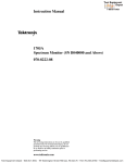
Period Measurements and Period Averaging
The 7D15 measures periods from 10 ns to 10 5 s . Up to
1000 periods can be averaged to obtain a resolution of up
to 10 ps .
The period mode measures the time between two points
on a waveform . These two points are selected by the A
TRIGGER controls such that the counter main gate turns
on and off at the point selected by the level and slope
controls, see Fig. 2-7a . The period averaging mode holds the
-PERIOD-~
PERIOD
PERIOD AVERAGED (X10)
B.
PERIOD AVERAGED
C.
TIM WIDTH A
+SLOPE
HYSTERESIS
WINDOW
-SLOPE
A INPUT
D.
TIME
INTERVAL
B INPUT
r
TIME INTERVAL
TIM A-rB
1432-13
Fig. 2-6 . Measurement intervals .
2-7
Operating Instructions-7D15
counter main gate on until 1, 10, 100 or 1000 periods are
counted (see Fig. 2-7b) .
Time Interval Averaging
Averaging makes possible time interval measurement as
short as six nanoseconds with a usable resolution up to 0.1
nanosecond . This increased resolution is achieved by
statistically reducing the t1 count error inherent in single
shot time interval measurements . The probability of
obtaining the true value increases with the number of
intervals averaged .
Time interval averaging can be used whenever several
repetitive intervals are available . The number of averages
selected (10, 100, or 1000) is largely determined by the
number of intervals available . Overflowing the counter
registers is another consideration for selecting the number
of averages .
Time interval averaging should not be used when the
interval being measured might vary during the measurement
cycle (a non-repetitive signal), or when signal repetition rate
is synchronized with the counter clock rate . The problems
of synchronization are discussed later.
Unlike period averaging (which turns the counter main
gate on for a certain length of time), time interval averaging
makes a predetermined number of discrete measurements,
then averages these measurements to obtain the final
answer . For instance, for 1000 averages, the counter main
gate is turned on and off 1000 times before the final answer
is ready .
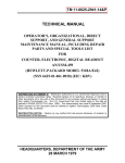
With a ten nanosecond clock, it is possible to obtain
accuracies of one nanosecond . For example, assume that
the time interval to be measured is 11 nanoseconds. The
measurement is made and the results are totaled 1000
times . In this case, a ten nanosecond clock is used . 1 .1
pulses of the clock will occur during the measurement
interval, so 1100 counts would be expected to occur during
1000 measurements . Since the counter cannot record a
fractional count, sometimes it registers one count and
sometimes two counts, depending on the timing between
the clock and the repetition rate of the interval to be
measured . Assuming a uniform random distribution of
timing coincidence, two counts are recorded 10% of the
time and one count 90% of the time . Figure 2-8 shows the
graphical representation of this example.
While time interval averaging reduces inaccuracies, the
amount is often difficult to determine . The period of the
interval to be measured is one variable in calculating the
I~---11 ns-~I
INPUT T. I .
TO BE MEASURED
1ST MEAS .
D MEAS .
1000TH MEAS .
INTERNAL
CLOCK
GATED OUTPUT TO
COUNT REGISTER
1 COUNT RECORDED
90% OF THE TIME
2 COUNTS RECORDED
10% OF THE TIME
EXAMPLE ASSUMES UNIFORM RANDOM
DISTRIBUTION OF TIMING COINCIDENCE.
Fig. 2-7. Graphical representation of time interval averaging.
2- 8
TOTAL NOMINAL
COUNT 1100
1432-14
Operating Instructions-71315
standard deviation. A probability distribution graph for the
previous example, where the time interval is 11 ns, is shown
in Figure 2-9. Compare this graph with the probability
distribution graphs for 10 .1 ns and 15 ns . The probability
range for a time interval of 10 .1 ns is narrower than for a
time interval of 11 ns or 15 ns . Readings in the shaded area
of the graph represent the range of answers that may be
given 50% of the time .
Another variable that can change the shape of the
distribution curve is the number of averages taken. The
graphs shown in Figure 2-10 represent the probability curve
of an 11 ns time interval that is averaged 10, 100, and 1000
times. The graphs show that the probability of obtaining an
answer of exactly 11 ns increases with the number of
averages taken .
1 .75
1.50
1 .25
F
J
m
a
m
O
a
1 .00
.75
.50
.25
.00
9.9
10 .0 10.1
10.2
10 .3 10.4 10.5 10.6 10.7
10 .8 10 .9 11 .0
RANGE OF ANSWERS Ins)
It should be noted that the previous examples assume a
uniform random distribution of time coincidence . If the
input time interval and clock is synchronized an erroneous
answer may be given ; see Figure 2-11 . The answer does not
vary, but is wrong . Anything short of pure synchronization
is usually acceptable .
If synchronization is suspected, a check can be made by
comparing the repetition rate of the time interval to be
measured with the 71315 clock rate . This can be done by
triggering the oscilloscope with the 71315 PSEUDO GATE
and observing the CLOCK OUT signal . Since all the 71315
Clock positions are synchronized with each other, for the
purpose of display, a lower clock rate position can be used .
Synchronization is indicated by a display with little or no
drift.
-
Number of averages
Repetition rate of measured time interval
Second, observe the waveform and measure the time of one
cycle of drift. Correct for the time interval actually used .
.050
CLOCK RATE = 10 ns
-
.045
AVERAGES= 1000
-
.040
J
Qm
a
.035
.030
.025
.020
.015
.010
.005
.000
The amount of acceptable drift can be determined first,
by calculating the time needed to make a time interval
average measurement (Tmeas) by the following :
Tmeas
TIME INTERVAL= 11 ns-
.055
10 .4
-0 -1 .[111111
.
10.5 10 .6 10 .7 10 .8 10.9 11 .0 11 .1
.0350
CLOCK RATE = 10 ns
.0275
m
Q
m
O
a
11 .4 11 .5
TIME INTERVAL = 15 ns
.0325
.0300
>F
11 .2 11 .3
RANGE OF ANSWERS (ns)
AVERAGES = 1000
.0250
jIII
.0225
.0200
I, .
lNllllllHIIINIIMI
.0175
.0150
.0125
!lIIIIIIIIIIIIIIlIIIIIillllllII~II
IIIIllilllllllllllIIIIIIlIIIIilllllMlll~ll~
111111!IIIIIIIIIIIIIIIIIIIIIIIIIIIIIIIUIII~lllfll~
.0050
~IIIIIIIIIIIIIIIIIIIIlIlIIIlIIIIIIIIIIIIillllllllllllllllllllm~
.0025
lllll~llllllllllllllllllillllllIIIllllll1111i111111IIIilIlIlllllllllllllllllltllhlll~
.0000
.0100
Generally, synchronization will not occur if this figure is
less than Tmeas .
Example : A time interval with a repetition rate of
100 kHz is being measured and averaged 1000 times, using
a clock of 10 ns .
Tmeas
1000
100 kHz
=
10 ms
.0075
14 .4
14 .5
14 .6
14.7 14 .8 14 .9 15 .0 15 .1 15 .2 15 .3 15.4
RANGE OF ANSWERS (ns)
15.5
THE ABOVE EXAMPLES ASSUME A UNIFORMLY RANDOM DISTRIBUTION OF TIMING COINCIDENCE.
1432-15
Fig. 2-8. Probability versus time interval .
2- 9
Operating Instructions-7D15
.500
AVERAGES = 10
.450
TIME INTERVAL= 11 ns-
.400
CLOCK RATE = 10 ns
.350
J
m
Qm
O
a
10 ns
logs
.300
.250
.200
.100
.050
9.0
10.0
11 .0
12 .0
13 .0 14 .0 15.0 16 .0
17 .0
18 .0
19 .0 20 .0
RANGE OF ANSWERS Ins)
.180
AVERAGES = 100
.160
m
a
0
a
1 .5 seconds
=
1 .5 ms
To eliminate a synchronous relationship, change the
input signal repetition rate, introduce some type of phase
instability to the input signal, or alter the 7D15 clock
frequency (two or three ppm is usually adequate) . Any of
these methods allow the counter to seek a true random
distribution of time coincidence .
TIME INTERVAL = 11 ns
.140
F
J
X
Since Tmeas (10 ms) is greater than the drift rate (1 .5 ms),
synchronization is not a problem .
.150
.000
The CLOCK OUT signal is viewed on the oscilloscope, using
an amplifier plug-in unit . The display is triggered with the
PSEUDO GATE . To present a usable display, the 7D15
clock rate is changed to 10 ps . A drift of 1 .5 seconds per
cycle is noted. This drift rate is corrected by :
CLOCK RATE = 10 ns
Selective Time Interval Measurements
.120
Selective time interval measurements are made possible
by using the 7D15 A ARM and B ARM gates. The
oscilloscope delayed gate can be used in conjunction with
the ARM gates to choose the portion of a waveform to be
measured . Refer to the oscilloscope and time base manuals
for complete information concerning gate outputs available.
.100
.080
.060
.040
.020
.000
10 .4
10 .5
10 .6 10.7 10.8
10 .9 11 .0 11 .1
11 .2
11 .3 11 .4
11 .5
RANGE OF ANSWERS Ins)
OPERATION AND CHECKOUT
055
.050
Introduction
045
These procedures demonstrate the use of the connectors
and controls of the 7D15, and also provide a means of
checking the basic operation of the instrument .
.040
.035
Q
O
a
Inl~p
.030
025
IIOIIII~
.020
015
IIIIIYIINIII~~WI
010
005
.000
Preliminary Setup
10 .4
10 .5
10 .6
10 .7
10 .8
~~~~IIM
10 .9
11 .0
11 .1
11 .2 11 .3
11 .4 11 .5
Install the 7D15 into a vertical compartment of any
7000-Series, readout-equipped, oscilloscope . Set the oscilloscope Vertical Mode and Trigger Source switches to the
proper settings .
RANGE OF ANSWERS (ns)
THE ABOVE EXAMPLES ASSUME A UNIFORMLY RANDOM DISTRI_
BUTION OF TIMING COINCIDENCE.
1432-16
Fig. 2-9. Probability versus number of averages .
2- 1 0
Install a 7B-Series time-base unit into a horizontal
compartment and set the oscilloscope Horizontal Mode
switch to the proper setting. Adjust the time-base unit
throughout the procedures to obtain an optimum triggered
display .
Operating Instructions-71315
2(l nis
20
INPUT
TIME
INTERVAL
GATED
OUTPUT
TO COUNT
REGISTER
- 1~
3 COUNTS
ANSWER GIVEN IS 30 ns
1432-17
Fig. 2-10 . Results of pure synchronization between the clock rate and input time interval .
Set the 71315 controls as follows :
NO TE
A and B TRIGGER
SLOPE
COUPL
SENS
LEVEL
SOURCE
To obtain the total time of a number of time
measurements, do not reset counter .
+
DC
.1 V
PRESET
INPUT B
Event Counter
1 . Set the 71315 GATE switch to OFF and set the
MODE switch to FREQ B .
DISPLAYED WAVEFORM
Switch
PSEUDO GATE
Manual Stop Watch
1 . Set the 71315 GATE switch to OFF and set the
MODE switch to PERIOD A .
2 . Select the desired counting interval
interval of 1 ms can be observed easily) .
3 . Turn the STORAGE
DISPLAY control to ~ .
switch
to
(a
OFF
counting
and
the
2 . Turn the STORAGE switch to OFF and connect the
signal to be counted to the B Input connector (a 0 .4 V,
1 kHz oscilloscope calibrator signal may be used to show
operation) .
3 . Use the GATE ON OFF switch to start and stop the
event counter . If necessary, adjust the B TRIGGER
controls to obtain proper triggering . The DISPLAY control
determines the length of time that the digital display is
shown on the CRT before the counter resets .
Period Measurements
4 . The 71315 is ready to count . Use the GATE ON OFF
switch to start and stop the counter . Push the RESET
button to reset the counter .
1 . Set the 71315 MODE switch to PERIOD A, the
AVERG switch to X1, the GATE switch to NORM, and the
CLOCK switch to the desired resolution .
2- 1 1
Operating Instructions-7D15
2 . Set the STORAGE switch to ON and the DISPLAY
TIME control to the desired repetition rate .
3 . Connect the signal to be measured to the A Input
connector and adjust the A TRIGGER controls for proper
triggering . Observe the PSEUDO GATE display on the
CRT.
NOTE
The CLOCK OUT signal may be used as the A Input
Signal to show operation. The period of the CLOCK
OUT signal is selected by the CLOCK switch.
Period Averaging
1 . Follow the procedures for Period Measurements .
2 . Set the AVERG switch to the number of averages
desired, i .e ., with the CLOCK OUT signal connected
through a 50 ohm terminator to the A Input, the CLOCK
switch set to 10 ns, and the AVERG switch set to X1000,
the 7D15 digital display will be "10.00 ns 1000X" ±1
count .
Frequency Measurements
1 . Set the 7D15 MODE switch to FREQ, the GATE
switch to NORM, and the TIME switch to the desired
measurement interval .
2. Set the STORAGE switch to ON and the DISPLAY
TIME switch to the desired repetition rate .
3. Connect the signal to be measured to the B Input
connector and adjust the B TRIGGER controls for proper
triggering .
NO TE
The CLOCK OUT signal may be used as the B Input
signal to show operation. The frequency of the
CLOCK OUT signal is selected by the CLOCK switch,
i.e ., with the CLOCK OUT signal connected to the B
Input, the CLOCK switch set to 100 ns, and the
TIME switch set for a 1 second measurement interval
the 7D 15 will read "10000.000 kHz 1000 ms".
Frequency Ratio Measurements
1 . Apply one of the signals to be compared to the EXT
CLOCK IN connector using one of the cables supplied with
the 7D15 . This signal is usually a standard to which the
other signal is compared . Move the internal Clock switch
toward the rear of the plug-in to the External clock
position, see Fig. 2-12 .
2 . Set the MODE switch to FREQ and the TIME
AVERG switch to X1 .
3. Connect the second signal (the signal to be compared) to the B Input connector . Adjust the B TRIGGER
controls for proper triggering .
4. The numerical readout located on the upper portion
of the CRT indicates the ratio of the B Input signal to the
EXT CLOCK IN signal .
5. To obtain greater resolution, the TIME AVERG
switch can be used to divide the EXT CLOCK IN signal by
10, 100, or 1000 . However, the decimal point for these
switch positions will be incorrect. To obtain the correct
answer, multiply the CRT readout by the correction factor
given in Table 1-1 . For example, the CRT reads 10000.00
and the TIME AVERG switch is set to X10 . The corrected
readout is 10 .00000 :1 .
1432-18
Fig. 2-11 . Internal/External clock switch .
2-12
Operating Instructions-71315
to be averaged . Set the GATE switch to NORM and the
CLOCK switch to the desired resolution .
TABLE 2-1
Frequency Ratio Decimal Point Chart
TIME AVERG
Switch
Position
x 1l
X10
X100
X1000
71315
Readout
0 .0000
00 .00
0 .000
0 .0000
Correction
Factor
X101
X103
X103
X103
2. Set the STORAGE switch to ON and the DISPLAY
TIME control to the desired repetition rate .
Corrected
Readout
0.0000
000.00
000.000
000.0000
:
:
:
:
1
1
1
1
TIM WIDTH and TIM WIDTH Averaging Measurements
1 . Set the 71315 MODE switch to TIM WIDTH A, and
the AVERG switch to the desired number of measurements
NOTE
The oscilloscope Calibrator may be used as the A and
B Inputs to show operation, i.e., connect a 1 kHz,
0.4 .V Calibrator signal to the A Input and set the
SOURCE switch to the outward position . With the
CLOCK set to 10 ns and the AVERG switch set to
X10, the 71315 digital display will be "1000.000ps
1OX"t calibrator accuracy.
Section 3-7D15
CIRCUIT DESCRIPTION
INTRODUCTION
This section of the manual contains a description of the
circuitry used in the 7D15 Universal Counter Timer plugin . The circuitry starts with a block diagram discussion .
Following the block diagram discussion is a detailed
discussion of the individual circuits .
A basic knowledge of discrete and digital electronics is
needed for a thorough understanding of the instrument . If
more information about commonly used circuits is
desired, refer to the following text books:
Jacob Millman and Herbert Taub, "Pulse, Digital, and
Switching Waveforms", McGraw-Hill, New York, 1965 .
To understand the 7D15 readout circuitry, a basic
knowledge of the Tektronix 7000-Series readout system is
required . A brief synopsis, labeled "Readout Theory" is
given in this section . More information is available in any
service manual for a Tektronix 7000-Series, readoutequipped mainframe.
LOGIC FUNDAMENTALS
Signal lines in this instrument are named to indicate the
state at which the indicated function is performed . For
example, the line labeled "RESET" means that the
affected circuits are reset when this line is HI ; the line
labeled "RESET" (RESET -NOT) means that the affected
circuits are reset when this line is LO .
BLOCK DIAGRAM DESCRIPTION
GENERAL
The following discussion is provided to aid in understanding the overall concept of the 7D15 before the
individual circuits are discussed in detail . A block diagram
of the 7D15 is shown in the Diagrams section . Only the
basic interconnections between the individual blocks are
shown on the block diagram . Each block represents a
major circuit within the instrument . The number on each
block refers to the schematic on which the complete
circuit is found .
The Block Diagram is broken into five functional
blocks : Input, Clock, Gate, Reset, and Counters and
Readout. The following Block diagram description is
divided into these five categories .
INPUT
The Input section conditions the signal for use in the
Gating circuitry. This section includes the signal source,
coupling, amplitude, polarity, slope, trigger level, A ARM,
and B ARM functions.
Input signals can be connected to the A or B Inputs,
depending on the mode used . With the Source switch in
the outward position, the signal connected to the A Input
is internally connected to the B input circuitry. The AC-DC
Attenuator Blocks select the type of coupling and the
amount of attenuation required . In addition, when the
7D15 is used in an oscilloscope horizontal plug-in compartment, the AC-DC attenuator circuitry can select the
oscilloscope internal triggers . These triggers are
generated in the vertical plug-in unit .
The signals pass through the AC-DC Attenuator to the
A Amplifier and B Amplifier, where the signal is amplified
and the do trigger level is selected . The Trigger Level
connectors can be used as an output to show the actual do
trigger level selected, or through the use of an external
power supply, can select the do trigger level.
CLOCK
The clock circuitry provides a standard against which
the input signal is compared . The standard is obtained
either from ; a precision crystal oscillator, which provides
the One Megahertz Standard, an external input connected
to the EXT CLOCK IN, orthe Voltage Controlled Oscillator
referenced to either the One Megahertz Standard or the
EXT CLOCK IN .
The One Megahertz Standard signal is derived from the
five megahertz crystal oscillator, by way of the - 5 block.
An external standard signal can be substituted by selecting the EXT Position of the External Clock switch and by
applying the external standard to the EXT CLOCK connector . The external clock signal is shaped for use with the
rest of the clock circuitry. The One Megahertz Standard is
connected to a series of decade counters to provide the
1 Ns, 10 /is, 1 ms, and 10 ms Clock signals. The 100-
Circuit Description-7D15
megahertz Voltage Controlled Oscillator (VCO) and
decade counter provides the 10 ns and 100 ns Clock
signal . The Voltage Controlled Oscillator is stabilized with
a phase-locked loop circuit, in which the 100 megahertz
output is divided by 100 and compared with the One
Megahertz Standard . The frequency difference from the
Phase Detector is a do error voltage and is presented to the
Voltage Controlled Oscillator to correct any drift.
After amplification and level selection, the signals are
shaped in the A and B Shapers. The signals are then
connected to the A Arm and B Arm circuitry (byway of the
Slope circuits) . This circuitry can, with the proper command, inhibit the signal from any further travel . A LO or
ground connection to the A ARM connector will inhibit the
B signal while a HI command at the B ARM connectorwill
inhibit the A signal . These signals, if not inhibited, are
connected to the gating circuitry.
eseeee
GATE
For simplicity, the Gate block is discussed in each
mode of operation . A block diagram, showing the main
signal flow, is given for each mode .
FREQUENCY MODE
Refer to Fig . 3-1 for signal flow . The frequency to be
measured is connected to the B input through the B
circuitry ; then to the main gate . The 10 ms Frequency
Standard is connected through the A Arm circuit to the
Gate Generator and the Arm Gate Generator . The 10 ms
pulse sets the Arm Gate Generator and the Gate
Generator HI . This enables the AND gate and opens the
Main Gate . Opening the Main Gate allows the B signal to
be counted. The next 10 ms pulse sets the Arm Gate
Generator LO, which causes the AND Gate to go LO,
turning the Main Gate off. A LO at the output at the AND
Averaging Signal Path
Channel B Signal
0
10ms Clock or Reference Signal
GgrE
Fig. 3-1. Signal flow for FREC! and Frequency Ratio modes.
3-2
1433-1
Circuit Description-7D15
Gate also flips the Initiate Generator and in turn generates
the Mono Update command . This starts the Timer. The
signal to the Mono Update causes the information in the 8
Decade Counters to be stored and converted into the
proper row and column set by the Display Time Control, a
reset command is generated; the entire instrument is now
ready for another measurement cycle.
of U390 goes LO, thus enabling the main gate, U386A,
which allows the unknown signal to be counted . With the
arrival of the next 10 millisecond clock, pin 2 of U374A
goes LO, pin 15 of U386D goes LO, and a LO is presented
to the D input of U390 . Pin 3 of U390 therefore goes HI with
the next pulse from the unknown signal . This enables the
main gate (U386A) and stops the counting process.
Frequency measurements can also be made by using
100 ms, 1 s, and 10 s Timing Standards. The process is the
same as for the 10 ms Time Standard, except that the
10 ms clock pulses are diverted, after passing through the
A Arm circuit, into a series of decade counters . The output
of the counters are selected by the TIME switch to give
100 ms, 1 s, or 10 s pulses . The Time switch also provides
commands to change the readout and legends for proper
readout (kHz, MHz, etc.)
INITIATE . Prior to the second 10 millisecond clock,
U374B was determined to be LO . This enabled U536B so
that the second 10 millisecond pulse clocks U409A. This
causes pin 3 to go HI, causing Q571 to turn on and Q574 to
turn off. The collector of Q574 goes HI, is inverted in
U530D, and connects through U530A to provide a gate
pulse. This starts the display-time multiplier (see reset
circuitry) . In addition, pin 6 of U530B goes HI and is held
HI, by the feedback loop of C581 and U530A, until C581
discharges. The pulse at pin 6 of U530B generates the
DISPLAY via U421 C and U266D. The contents of the
counters are stored, encoded, then read out on the crt.
FREQUENCY MODE . In the frequency mode, U360A is
enabled, allowing the frequency to be counted, (from the
B Arm circuitry) to pass to U38613 and U390 . This unknown
signal is connected to the main gate (U386A) via U386B.
This signal also clocks a D flip-flop U390 . The D input of
U390, derived from the 10 millisecond time standard,
remains high for 10 milliseconds . The signal path for U390
arrives via U286A, U287C, U290C, U287D, and to pin 9 of
U374A and pin 9 of U374B . U374B, which was set prior to
the start of the measurement cycle (see Reset Circuitry), is
clocked by the 10 millisecond standard . This causes pin 15
to go LO thus enabling U386D . The 10 millisecond
standard is also clocked through U374A, inverted in
U386C and passed through the enabling gate U386D. Pin
15 of U386D therefore goes HI, presenting a HI to the D
input of U390 . With the arrival of the unknown signal, pin 3
FREQUENCY RATIO
Refer to Fig. 3-1 for signal flow . An external time
standard can be used for frequency measurements by
setting the gate switch to OFF. This replaces the 10 ms
Frequency Standard with the signal connected to the A
Input. Frequency ratio measurements are made in this
mode .
FREQUENCY RATIO. The operation in the Frequency
Ratio mode is the same as for the frequency
measurements, except the internal 10 millisecond standard is replaced by the signal connected to the EXT
CLOCK connector. Refer to the discussion of the clock
circuitry.
Circuit Description-7D15
U266C, U351 B, and
(via Q460) and sets
U386D LO, placing
eventually inhibiting
EVENTS
Refer to Fig . 3-2 for signal flow . The front panel GATE
switch is set to ON . This opens the Main Gate and allows
the signal to be counted . Pressing the GATE switch to OFF
closes the Main Gate and provides an initiate command to
complete the cycle.
Q354 ; from whence it clears U374A
U374B (via Q367) . This in turn sets
a LO at the D input of U390, and
the main gate (U386A).
PERIOD
EVENTS . In the events mode, the signal to be counted
is connected to channel B. The signal to be counted is
connected to the main gate (U386A) via U386B, U360A,
and U390D. The main gate is enabled by placing the GATE
switch to ON . This clears U374B and sets U374A. This
causes pins 12 and 13 of U386D to be LO, pin 15 goes HI
and the D input of U390 goes HI . The signal to be counted
clocks U390, pin 3 goes LO and U386A is enabled. When
the GATE switch is set to OFF, the signal passes through
Refer to Fig. 3-3 for signal flow . The period to be
measured is selected from the signal connected to the A
Input. The trigger level is selected by the coupling switch,
attenuator, level controls, and slope controls . The signal
passes through the A Arm circuit to the Gate Generator
and Arm Gate Generator. The outputs of the Gate
Generator and Arm Gate Generator go HI . This causes the
AND Gate to go HI and the Main Gate opens.
wr r _ ® Control Signal (manual)
Clock Signal
B ARM
Q775 U287B~
g277 U190B,D
q1.so
DISPLAYED
WAVEFORM
SWITCHING
g9D3
V29SA,B,C
5500
CR512
uxao
PVL5E
GENERATOR
U2. 7A
V571C
BY-PASS
AMPLIFIER
U19gA
US60C
TIM
A+B
POSITION
Q227
U266C U060B
TIM
wI .T . A
To 8 Decade Counter
- Q375
TIM
b4y8
A ARM
A 40.M
CH A INPOYp
I
CLOC K
IO'S
E
SWITCHING
Q459
U2665
U111D
Q445
Q447
U411B
I
Q424
Q417
Q429
Q467
V460 A
TIM
E
FREQ E
PERIOD
AV ERG
D GATE Q
GENERATOR
CP
U2688
U551A
U4SO
U374A
AND
GATE
U S1"9
Q 399
I
U 38 6A8
Q
V 586C,D
D
MAIN
GATE
Q
~REQ
U187C, D
U2. 0C
U560D
CLOCK ~4
U386A
0590
AVERAGING
COUNTERS
5599
AV ERG
8509 U519
Q512
U521
Q521 U556AC
U463 A,B
U4
U461
B9B
U496A,B
U4994I B
QS51
U3 SIC
TM
AV ERG
D
INITIATE
CP
ESET
5
ARM
CP GATE
Q5G7
CP Q591
U374B
U371S
U409A U536B Q
~ CR25~5
3-4
HOLD 811E
SSB4
STORAGE
DISPLAY
UP DATE
GATE
Q571
g574
GL-,B4
U264C,D
U166D
U421A,C
U550A,B,D
~A22 BUSY
'7~
J
GAT E
Fig. 3-2. Signal flow for Events mode .
Q
1433-2
Circuit Description-7D15
In the period mode, the clock frequency selected by the
CLOCK switch is connected to the Main Gate . When the
Main Gate is open, the clock pulses are counted in the 8
Decade Counters . The second waveform from the A
circuitry sets the Arm Gate Generator LO, and in turn sets
the AND Gate LO, thus closing the Main Gate . The initiate
command is given and the storage, read, and reset cycles
are completed .
PERIOD . The period of a waveform is measured by
counting the number of clock pulses that occur within the
period . The clock is connected to the main gate (U386A)
via U371 A and U386B . The period waveform is connected
to U374A and U475B via U287C, U290C, and U287D . The
period pulses clocks U274B, pin 15 goes LO and U386D is
enabled . U374A is also clocked, pin 2 goes HI, is inverted
in U386C and presented to U386D . This causes the D input
of U390 to go HI . A clock pulse from Q393 causes pin 3 of
U390 to go LO, thus enabling the main gate U386A . This
allows the clock to be counted . With the arrival of the
second pulse (signifing the end of the period to be
measured) U374A is clocked, U386D is inhibited, the D
input of U390 goes LO and U386A is inhibited . Also, the
initiate commands are given via U409A.
PERIOD AVERAGING
Refer to Fig . 3-3 for signal flow . The period averaging
mode uses the same procedure as the period mode,
except that the signal from the A Arm circuit is routed
through a series of decade counters . The number of
averages correspond to the counters switched in by the
Average switch .
PERIOD AVERAGING. Period averaging is achieved by
holding the main gate (U386A) on for 10, 100, or 1000
periods. This is accomplished by deflecting the A input
through the averaging counters . In the period averaging
mode, the LO state of PERIOD, (coupled through U371 D,
Q459, U266B, and U351A) disables U290C and enables
U360D. The channel A signal is connected to the averaging counters via U463A. The operation of the averaging
counters for the period mode is similar to the operation in
the frequency mode .
Clock Signal
Channel A Signal
D111-1WAVEF02M
SW rtCM NG
Averaging Signal Path
Q303
U295A,BL
5900
From A Slope Switch
MAIN
GATE
Q
Cv
U3 86A
U 990
AVERAGING
COUNTERS
ymm
5599
,509
U519
Q512
.521
U5~
,529
U4634,8
U 47 BBL
U4B9B
U096A,B
U 994,B
5584
RESET
01 S7 LAY
UPDATE
GATE
Q9ll
QS74
,584
U264C,D
U2 6D
U411A,C
U590A,B,D
L R2 5
A22
BUSY
GATE
1433-3
Fig. 3-3. Signal flow for PERIOD mode.
3-5
Circuit Description-7D15
amplifier etc ., is connected to the Gate Generator clear
input. This sets the Gate Generator output LO and closes
the Main Gate .
TIM WIDTH A
Refer to Fig. 3-4 for signal flow . The signal at the A input
is processed through the attenuators, amplifiers, shaper,
slope circuit, and A Arm circuit . This signal bypasses the
Gate Generator via the Bypass Amplifier. The signal also
flips the Arm Gate Generator HI, which in turn opens the
Main Gate to allow the clock pulses to be counted .
TIM A-B AND TIM WIDTH A AVERAGE
Refer to Fig . 3-4 and Fig. 3-5 for signal flow . The
averaging procedure for the TIM mode is different than for
the period or frequency modes of operation . The TIM
averaging modes allow the Main Gate to open and close
10, 100, or 1,000 times. This is accomplished by disabling
the Initiate Generator until after 10, 100 or 1,000
measurements are made . The input signal is connected to
the Averaging Counters via the Bypass Amplifier in the
TIM WIDTH A mode, or to the Gate Generator in the TIM
A-B mode . The output of the Averaging Counters inhibits
the Initiate generator until after 10, 100, or 1,000 pulses of
the input signals are counted . The Initiate generator, in
turn, clears the Arm Gate and holds it until after the
preselected number of averages . The AND Gate,
therefore, opens and closes to allow the main gate to make
10, 100 and 1,000 separate measurements .
TIM A--B
Refer to Fig . 3-5 for signal flow . The TIM A--B mode, in
effect, opens the Main Gate with a trigger from the A Input,
then closes the Main Gate with the a trigger from the B
Input. The procedure is as follows : The A signal is
processed through the attenuators, amplifiers, shaper,
and slope circuit . The signal is then connected to the Gate
Generator and Arm Gate Generatoras in the Period mode .
The AND Gate goes HI and the Main Gate opens . The B
signal, after being processed through the B attenuator,
Channel A Signal
Clock Signal
Averaging Signal Path
GATE
1433-4
Fig. 3-4 . Signal flow for TIM WIDTH A mode .
3-6
Circuit Description-7D15
OUTPUTS
The Display Waveform Am plifiercan present anyone of
three waveforms . The Pseudo Gate, CH B, or True Gate .
The Pseudo Gate signal is the Gate Generator output . This
waveform represents the time that the Main Gate would be
open if the Arm Gate Generator would allow it . The True
Gate waveform is the actual time that the main Gate is
open . The CH B output of the Displayed Waveform
Amplifier is the B signal after it has been processed
through the attenuators, amplifiers, shaper, slope
amplifier, and B Arm circuit .
COUNTERS AND READOUT
Pulses from the Main Gate are counted by the Eight
Decade Counters . Upon a Display Update command, the
information is stored and converted into the proper row
and column currents necessary to encode the Tektronix
7000-Series readout system .
Decimal point, legends, etc., representing the state of
the front panel switches, are also converted into row and
column currents to encode the Tektronix 7000-Series
readout system .
RESET
The internally generated Reset and Reset signals ar
generated at the end of display time or by a Ext Reset
command . The function of the Reset and Reset commands
are to set the Eight Decade Counters, set the Averaging
Counters, provide a busy signal to external equipment,
and to set, then clear, the Initiate generator . Ext Reset
resets the entire instrument, including the display.
Clock Signal
Channel A Signal
DISPLAYED
AVEFOkM
SWITCHING
Averaging Path Signal
""" ** " * Channel B Signal
QB01
_11A,.,C
5000
PULSE
GENERATOR
u2914
V911L
From B Slope Switch
BY - PASS
AMPLIFIER
U2'0A
-11-
From A Slope Switch
A ARM
A4RM
_'Y
CL0CR
4
To 8 Decade Counter
t
SWITCHING
4445
Q447
U41,a
Q424
Q421
Q429
g468A
Q459
U 260B
U07ID
FREQ
I
(
ER IOU
AvERG
U$ IA
.450
U 28l C,D
U290C
USbOD
0
GATE
4
GENERATOR
CP
D
US'4A
MAIN
GATE
Q
0
CP
U9B0A
0990
AVERAGING
COUNTERS
5599
IMPM
Q509
V 519
0921
g512
U59GlyC
Q529
U4bB4,B
I
U 410 B,C
04698
U49A,B
U 4994,B
-1515111 C
D
Q
SSB4
INITIATE
CP
RESET
UIB
0
u44 O.A
.5
U59
q
HOLD 622
CR2
5
y1
GATE
DISPLAY
UPDATE
GATE
Q511
QSl4
4584
UTG4C,O
U24(.D
U411A,D
U1S .A,B,D
A22
U-
1433-5
Fig. 3-5. Signal flow for TIM-B mode .
3-7
Circuit Description-7D15
TRIGGER INPUT AMPLIFIERS
Refer to Diagram 1 . Connectors J1 and J101 provide a
means for connecting the A and B signals to the 7D15 .
With the A COUPL switch in the DC position, the signal
connected to the CH A input is connected to the A SENS
switches through C4 and R4 . With the A COUPL switch in
the AC position, the path is through C2, and R2, and the do
blocking capacitor C5 . The A signal then passes through
the X100 attenuator, the X10 attenuator, or passes directly
to the AC Amplifier, depending upon the A TRIGGER
SENS switch position . The attenuators are hybrid devices
that furnish the appropriate attenuation and compensation . Each attenuator is replaceable as a unit .
The trigger source position of S11 and S111 disconnects the A or B signal and connects the internal
trigger signal .
frequency range. L41 couples the do signal to the shaper
and prevents U43 from degrading the high-frequency
performance of the AC Amplifier.
SHAPER
The outputs of the AC and DC Amplifiers are connected
to the Shaper circuit, consisting of 060 and 065, a fast
Schmitt Trigger. VR67 and VR69 provide do offset
necessary to drive the following stage (slope circuit) .
SLOPE CIRCUITRY
The signal from the Shaper circuit is connected to
paraphase amplifiers Q72-074 and Q79-081 . With S89 in
the + position, Q72 and Q74 are held off; Q87 is forwardbiased, thus providing emitter current to 079 and 081 .
The signal is passed through T75 to the next stage. With
S89 in the - position, Q87 is turned off and emitter current
is provided for Q72 and Q74.
INTERNAL TRIGGER
The 7D15 has access to the oscilloscope trigger signal
when plugged into an oscilloscope horizontal plug-in
compartment. This differential trigger signal is connected
to differential amplifier Q203-0213, via pins A20 and B20
of the Mainframe connector ; see Diagram 1 . 0203 and
0213 form a paraphase amplifier. The base of Q217 (a
single-ended amplifier) is driven by Q203 ; the emitter of
0217 is driven by Q213 . CR203 provides the offset
necessary for proper operation of 0217 . The output of
0217 is ac-coupled through C219 to provide inputs to the
A and B Amplifiers .
A AMPLIFIER
The input signal is connected to the AC Amplifier,
which consists of 025, Q32, and Q38, and the DC
Amplifier, consisting of U43. R17 provides the one
megohm input resistance . R18 is a current limiting resistor
and C18 provides ac bypass . CR20, CR21, CR22, and
CR23 provide overvoltage protection for the amplifiers .
Q25 source follower is ac-coupled through C27 into
amplifier Q32, and the low output impedance amplifier
Q38. R31 provides the high-frequency gain adjustment for
Q32. VR36 provides the 12-volt supply for Q32 and Q38.
The output of the AC Amplifier is ac coupled into Schmitt
Trigger Q60-065 .
The do path for the input signal is provided by amplifier
U43. The input signal is connected to the non-inverted (+)
input of the operational amplifier through R44. R49 sets
the quiescent do operating level for amplifier U43. R57, the
LEVEL control, is used to select the do operating level of
U43. J52, trigger level jack, provides a means for monitoring the level set by R57, or it can be used to provide an
external trigger level. A portion of the ac signal from Q38 is
connected into the feedback loop of U43 to keep the
output of both of the amplifiers constant throughout the
3-8
TIME BASE
TIME STANDARD
Refer to Diagram 4 . The five-megahertz crystal oscillator (Y622) output is divided by counter U625, then
used as the One-Megahertz Standard signal for the 7D15 .
With S626 in the EXT position, an external standard can be
used .
Asignal connected toJ601 is ac-coupled to the Schmitt
Trigger (0606-0614) through C603. R602 provides
current limiting and C602 provides ac bypass . CR603 and
CR604 are over-voltage protectors . R613 provides positive
feed-back for high-speed operation . The output of the
Schmitt Trigger is coupled through amplifier 0620 to
provide the external standard .
CLOCK SIGNALS
The 1 Ns, 10 ps, 1 ms, and 10 ms frequency standard
are derived directly from the One Megahertz Standard .
CLOCK switch S699, in conjunction with the four nand
gate sections of U676, selects the appropriate frequency,
counted down from the One Megahertz Standard by
decade counters U665, U668, and U671 . After selection,
the signal is coupled to U371A (Diagram 2) and Q694Q696, the Clock Out circuit. After conditioning by the
Clock Out circuit, the signal is coupled to front-panel
CLOCK OUT connector J697, by way of connector J696 .
Selection of the 1 /is position of the clock switch S699
presents a LO to the input of U678B and a HI to pin 8 of
U676C. This enables U676C and allows the One
Megahertz Standard to pass directly through to the Clock
Out circuit.
Circuit Description-71315
Selection of the 10 ,as position of S699 presents a LO to
U678C and a HI to U676B. This enables U676B and allows
the output of decade counter U665 to pass . The output of
U665 is the One Megahertz Standard divided by 10 .
Selection of the 1 ms position of S699 presents a LO to
U678D and a HI to U676A . This enables U676A and allows
the output of decade counter U671 to pass . The output of
U671 is the One Megahertz Standard divided by 1000 .
The 10 ms frequency standard is derived by dividing
the One Megahertz Standard by 10,000 in U665, U668,
U671, and U674 . The reset command connected to pin 1 of
U674 ensures that the 10 ms frequency standard will be
ready.
ARM INPUTS
A ARM
With no input, Q445 is biased off by divider R441, R443,
and R444 . This forward biases 0447, which holds the data
input of U450 (Pin 11) HI . With the arrival of a clock pulse
(derived from the Channel A input, via 0429, or in the
frequency mode, the 10 ms clock, via U268A and Q467)
pin 3 of U450 will go LO . This enables Gate U287D to allow
the Channel A signal to pass . Gate U360D is also enabled
to allow the averaging modes to be used . To disable the
input, a ground is connected to the A ARM input. This
forward-biases 0445, reverse-biases Q447 and in turn
places a LO at the data input of R450 . With the arrival of the
next clock pulse, pin 3 will go HI to inhibit U287D and
U360D.
B ARM
The 10 ns and 100 ns clocks are derived from the 100
megahertz oscillator U643 . Selection of the 10 ns position
of S699 presents a low to Q687 . This turns Q687 on and
allows Q689 to turn on . 0689 then passes the 100
megahertz output of U643 to the Clock Out circuit.
Selection of the 100 ns position of S699 causes the
output of U678A to go low. This enables U676D and allows
the 10 megahertz output of Q660 to pass . The
10 megahertz output of Q660 is derived from the 100
megahertz oscillator, U643 . U647A, U647B, U654A, and
U654B compose a high speed decade counter. Q655 and
Q660 is a buffer used to match the MECL output of Q647B
to the TTL input of U662 .
100 MHz OSCILLATOR
U643 is a voltage-controlled oscillator and is connected
in a phase-lock loop with the One Megahertz Standard,
The output of U643 is divided by 100 by decade counters
U647A, U647B, U654A, and U654B and by decade counter
U662 . The output of U662 is approximately one
megahertz . This one megahertz signal is compared to the
One Megahertz Standard in U628A . The resulting output
of U628B is a do voltage level representing the phase
difference between the One Megahertz Standard and the 1
megahertz signal from U662 . This do voltage level is
connected through source follower Q633A to amplifier
U628C . 0633B is a current source to provide stabilization
for Q633A. The do voltage at pin 8 of U628C is connected
to varicap CR641, which in turn corrects the frequency of
100 megahertz oscillator U643 . L641 is adjusted (by
squeezing or expanding the coil) to ensure that CR641 is
at the center of its operating range. C638, C637, and R637
are used to slow the reaction time of the phase detector .
With no input to the B ARM, Q275 is forward-biased .
Q277 is reversed-biased and Pin 11 of U280 is LO,
enabling gates U287A and U295D . +5 volts, applied to B
ARM, will reverse-bias Q275, forward-bias Q277 and apply
a HI to pin 11 of U280 . With the arrival of the next clock
pulse (derived from the channel B input via Q285), pin 2 of
U280 goes HI to disable gates U287A and U295D. The
polarity of the B ARM command can be reversed by
moving the internal strap to connect U290D with the CU
output of U280 (pin 3) . This mode of operation requires
+0 .5 volt at the B ARM connector to allow the signal to
pass . Removal of the +0 .5 volt will inhibit the signal .
RESET CIRCUITRY
The internally generated RESET and RESET pulses are
generated at the end of the disp layed ti me or by Ext Reset.
The function of the RESET and RESET pulses is to set the
eight decade counters, set the averaging counters,
provide a busy signal for external equipment, and set, then
clear, U409A (to start a new measurement) .
RESET and RESET pulses are generated as follows: At
the end of display time, unijunction transistor Q258 will
switch on momentarily. A positive pulse is applied through
C261 to reverse-bias diode CR262. This momentarily
removes the LO from the input of U264A, which in turn
applies a momentary LO at Pin 2 of U266A and a
momentary HI on the RESET line . A few nanoseconds
later (the transi t time of U268D), a momentary LO is
presented to the RESET line . The RESET line is connected
to the set inputs of counters U401, U40913, U413A, and
U413B. The RESET line is also connected to pins 1 and 2 of
U289A. If the instrument is not in the Period mode, pin 12
of U489A will go LO, and pin 8 of U489C will go
momentarily HI . This sets or clears the averaging
counters : U519, U521, U496A, U496B, U499A, and U499B.
(U409A is also set.) The RESET, which occurs a few
3-9
Circuit Description-7D15
nanoseconds after RESET, is delayed even longer through
U264B and U530C. The delayed RESET pulse is then
differentiated by C532 and LR532, and used to clear
U409A. (U409A was just set by the RESET pulse.)
five, 0.6 milliamp of column current and 0.1 milliamp of
row current is necessary . Refer to any 7000-Series,
readout-equipped oscilloscope service manual for
detailed readout information .
The RESET line is also connected to U264D, which
provides a LO to pin 1 of U421A and a HI to the busy line .
CH 1 COLUMN AND ROW DATA
Complete resetting of the entire instrument, including
the display is initiated by the EXT RESET line . The EXT
RESET command is generated by applying a HI to the
front panel RESET connector, pressing the RESET
pushbutton, switching the gate switch to NORM, or by a
command th rough the rear interface connector (131 5) . The
EXT RESET comman d generates a RESET and RESET
pulse via U266A. The EXT RESET is also connected to pin
10 of U421 C. The EXT RESET command causes pin 8 of
U421 C to go HI and, if there is no external hold command
connected to B22 of the rear interface connector, the
display line will go LO, thus resetting the display readout.
EXT RESET also connects to pin 5 of U351B, where it
clears U374A and presets U374B.
Q490 and U478A are used, in addition to the previously
discussed reset lines, to accommodate the various modes
of operation. When the gate switch is placed into the OFF
position or taken out of the OFF position, the averaging
counters are reset and U409A is set. When the gate switch
is set to OFF and when not in the FREQ mode, the
averaging counters are reset and U409A is set and held .
This is to allow frequency ratio measurements .
READOUT THEORY
GENERAL
The 7D15 displays its readout on the upper and lower
portion of the oscilloscope crt. The upper readout contains the numerals, decimal point, and overflow indicator
(>) . The lower word location gives the units in which the
measurements are made (MHz, us, EVENTS, etc .) . The
upper readout (Channel 1 readout) is discussed first .
Tektronix 7000-Series readout systems contain timeslot pulses corresponding to each letter of signal in a
word . Ten time slots are available for each word . A row and
a column current return line is associated with each word
location . In the case of the 7D15, there are two word
locations available, the upper crt readout and the lower crt
readout. All that is required to encode a letter or signal is to
connect the correct value resistors between the desired
time slot and the row and column return lines. The value of
the resistors determine the current flowing into the row
and column return lines. The matrix (Figure 3-6) shows the
row and column currents necessary to select any of the
available symbols. For instance, to display the number
3- 1 0
Refer to Diagram 5 . The 7D15 has a measurement
capacity of up to 8 digits . Each of the 8 digits has an
associated time-slot line . The time-slot line number 2 (TS2) corresponds to the most significant digit in the readout.
Time-slot number 9 (TS-9) corresponds to the least
significant digit. Time-slot 1 is used to encode the
overflow indication (>) . Time-slot 10 is used to encode the
location of the decimal point. Since time-slot 10 is the last
pulse to occur, it is also used for a transfer pulse.
DECADE COUNTERS
Refer to Diagram 4. U741 is a BCD-to-analog converter.
It supplies current from time-slots 1, 8, 9, and 10 to the
column return line . The magnitude of current corresponds
to the BCD input. Inputs at pins 1, 2, 3, and 4 are active only
during time-slot 9 and thus are the units input. The output
from the biquinary counters (divide by 2-divide by 5) on
Diagram 2 is connected to the biquinary to BCD converter,
which consists of Q703, 0705, Q709, Q711, Q713, Q715,
Q717, Q719, U725A, U725C, and U725D . The output of the
biquinary to BCD converter is connected to pins 2, 3, 6,
and 7 of U735 . U735, at the propertime, will store the count
and transfer it to U741 . The O output pulses of the
biquinary counter equal one-tenth of the actual count.
These pulses are connected to the decade counter U728
via 0703 and 0701 . The BCD output of U728 is connected
to storage register U732 which, at the proper time, stores
the count and transfers it to U741 . The BCD output of U732
corresponds to the tens digit . R743 and R744 supplies the
extra 0.1 mA of current needed to correct the output of
U741 .
The C and D outputs of U728 are connected to the clock
input of U587 . CR729 and CR730 connect the C and D
outputs of U728 to provide a wide, usable pulse.
U758 contains four decade counters, four 4-bit storage
registers, and four BCD- to-analog converters . The BCD
to analog converters are connected to, respectively, timeslot 7, time-slot 6, time-slot 5, and time-slot 4. This
provides the proper column currents for the 100's, 1000's,
10,000's, 100,000's digits . R756 standardizes the current
levels so that they are compatible with the oscilloscope
readout system . Pin 6 of U758 is the current output line .
The count output of U758 is connected to the input of
U762 . U762 is similar to U758, except only two decade
counters and two 4-bit latches and two BCD-to-analog
converters are used . Pins 14 and 13 supply the time-slot 3
and time-slot 2 pulses for the 1 millions and 10 millions
digits . R760 standardizes the output of U762 so that it is
compatible to the oscilloscope readout system .
Circuit Description-7D15
0
0
a)
A
QC
Lai
O
I
U
00
o
d
i
d
li
j
o
v
U
CO
U
i.
i
Z
J
aF°~
n
+
^o
U
U0VZ
wa0
O J
J
Z
m
aF O o
o
U
Sc
L0
-Z3
Q-
W
O
a
U~
U
o
v
q
U
CI?
U
+
X
~W
N Ca
M
Ci
o
N
Z
H
00
OCC
aN
ZZ
a
S
~.
N
a0
~x
~w
1<
U0UZ
C
J
L9
Z
O aOUZ
O
J Z
aF 0~
6z
Wa ao
C
Q
J
i
~a ?FOarI)
0
W
O
a
f
a
X
w
w
~
,
F
w
'
~ ? QO
WOUZ
C]
Ow
wJ
m
O
a
000
0 3: CC
C~
N
I
OW0
0
0
0
J
07
UZ
<<O N
E
a
o
U
Z CL
~W
OCO
,.
w J Cc
MCC J w
a.
U
DU
O<ZJa
N
Z -w
O
Gw
u.
0
Z
_O
(NZ
a
UZ
Z
aFoM
ya
WF
N
N
F
ay
O
17
O
N
O
M
O
d'
O
In
O
(q
O
rl~O
CC
O
7
cc
N
cc
M
cc
V
cc
In
cc
(C
cc
r
CO
cc
C7
cc
N
O
>
a
N
(Nn
w
0
a
a
U
O
a
Z
O
0
Z
O
O
WN
O
F
a
Wa
6)
O
a
~~ Cc
cc:
co
Z
1195-25
Fig . 3-6. Character Selection Matrix for 7000-Series Readout System .
3- 1 1
Circuit Description-7D15
CH 2 COLUMN/ROW DATA
Refer to Diagram 6. Column converter U890 and Row
converter U898 provide appropriate column and row
currents when one or more inputs (pins 1 through 13 and
pin 20), receive a low, and in turn are interrogated by timeslot pulses applied to pins 14, 15, 16 and 17 . Various
symbols and combinations of symbols have been given
word designations, and are shown in a matrix . See Fig . 3-7.
With the NORM switch depressed, current is steered to
the inputs of the Column and Row converters by TIME
AVERAGE switch S599 and CLOCK switch S699, which
select the desired character or possible combinations of
characters for display on the crt. Depressing the FREQ B
button and cancelling the NORM button will produce the
EVENTS character.
With the FREQ B button depressed, a high is placed at
the bases of 0815 through Q821, turning those transistors
on, which in turn pull down on the bases of 0823 through,,
Q861, turning them all off. Pin 12 of U790D and the
emitters of Q869, Q874, and Q879 also receive a high,
turning them all off. When the ON or OFF mode switch is
depressed, a NORM is received at pin 13 of U790D, making
it high . This causes pin 11 to become low and turns off
Q884 . This turns of Q866, Q870, Q875, and Q880 by
removing their emitter current. So, in the FREQ mode and
the NORM switch out, a low appears at pins 20 of U890 and
U898 . This is the input for the word twelve, which is
displayed as EVENTS when both IC's are strobed from
time-slots 3 through 8. Therefore, whenever the frequency
mode is used, the CLOCK and TIME switch have no effect
on the display and only the word EVENTS will be
displayed.
TIME SLOT NUMBERS
1
ONE
Two
2
3- 1 2
5
- 1
M H Z
K H Z
n
S
-
1
FOUR
p
S
-
1
FIVE
m
S
-
1
six
S
E
TWELVE
13
12
11
-
1
V
E
j
6
j
I
(SEVEN)
0 0
0
'
- 1
THREE
7
8
(EIGHT)
0 0
I
I
1i
0
1
I
I
I
(NINE)
10
j
9
I
(TEN)
m
S
I
I
I
I
I
1
I
1
(ELEVEN)
X
1I
I
1I
I
1
; N
I
I
S
T
I1
1
I
ONE
TWO
THREE
10
FOUR
9
FIVE
six
5
4
3
2
1
20
U890
SEVEN
19
U898
EIGHT
NINE
TEN
ELEVEN
TWELVE
A
14
Characters may be displayed from the selections of
TIME switch S599, when in the Frequenc y mod e, by
depressing the NORM switch . This causes a NORM (low)
at pin 13 of U790D, causing the output of U790D to go
high . This cancels the EVENTS display and turns on Q884,
providing emitter curr ent to transistors Q866, Q870, Q875
and Q880 . The NORM also turns on Q803, which provides
current for TIME switch S599 . Depressing the 10 ms
button on TIME switch S599 causes a high at the. base of
Q866, pulling its collector down . This low is coupled
through CR865 and on to the DP5 line, which causes the
decimal point 5 to be displayed . A low is also coupled
through CR866 and CR867, placing a low at pins 13 and 3
of U890 and U898 . Pin 13 is word one, and writes MHZ 1 .
Pin 3 is word nine and writes one 0. With Q884 conducting,
its collector is low, which gets coupled through CR884,
placing a low at pin 2 of U890 and U898 . Pin 2 is word ten
and writes ms . So, with the TIME switch in the 10 ms
position, the characters MHZ 10mS is displayed on the
lower readout location of the crt.
4
3
B
C
115
117
D
116
1433-6
Fig. 3-7. Symbol and Word designation Matrix .
The characters for the 100 ms and 1 s switch positions
are developed in a similar pattern. However, in the 10 s
position, the 0896 circuitry ("milli-cruncher") is required
for a proper readout display. In the 10 s position Q880 is
turned on, its collector goes low, and the low is then
coupled through CR878 and on to the DP5 line . A low is
also coupled through CR880 and CR881, placing a low at
pins 12 and 2 of U890 and U898 . Transistor Q884 still
remains on, so we see characters KHZ 10mS displayed on
the crt. To correct the reading, the character m must now
be removed . Referring to Fig . 3-6, Character Selection
Matrix, the lower case m requires 100 NA of column
current, and is written during time-slot 9, as illustrated in
Fig . 3-7. Transistor 0896 serves as a three-input NAND
Circuit Description-7D15
gate, with TS9, pins 12 and 3 of U890 providing the inputs .
These three lines are low during time-slot 9, which turns
off Q896 and raises its collector up . This causes a 100 NA
current drop across R897, subtracting it from the column
output line . Thus, no current is available during time-slot
9, and the character m is removed from the readout
display. Since 300,uA of row current is being supplied
during time-slot 9, and a total of 900 pA of current is
needed to add a space in the display, the character s
moves over next to the character O.
The characters for the CLOCK switch S699 positions,
in conjunction with TIME switch S599 are developed in a
similar pattern and produce the various symbols and
combinations of symbols as illustrated in Fig. 3-7.
A diode matrix provides time-slot information to the A,
B, C, and D inputs of Digital-Analog converters U890 and
U898 in BCD code, but displaced by a count of one. Timeslot 2 pulls down on A input, TS3 on B input, TS4 on both A
and B inputs . This results in a BCD count of 1, 2, and 3,
rather than 2, 3, and 4 . Time-slot 1 doesn't enter the IC but
this information is produced when A, B, C, and D inputs
become high . Normally, this would produce a 0 count.
However, the displacement of 1 pattern causes this to be a
count of 1 . During this time, the internal resistors are all
interrogated, depending on what word is selected at the
input, and provides the proper row and column current for
the display information .
OVERFLOW
When an overflow condition occurs, a HI appears at Pin
3 of U762 . This causes Q782 and 0778 to latch, putting a
LO at Pin 10 of U790C. This causes Pin 4 of U725B to go
LO, giving an overflow command to U741 .
GATING
Because of the complexity of the various modes of
operation, the gating circuitry is discussed in each mode
and we use a > symbol displayed at the top of the screen .
AVERAGING COUNTERS . If a time standard other
than 10 millisecond is used (front panel TIME switch set to
100 ms, 1 s, or 10 s), the 10 millisecond clock is deflected
through the averaging counters . In the 100 ms, 1 s, and
10 s positions (not X1), U371 D disables U290C and
enables U360D; U463A is enabled at pin 4 via Q459 and
U266B. This deflects the 10 millisecond clock through
U463A to the decade counter consisting of U496A, U496B,
U499A, and U499B . When the front panel switch is set to
100 ms (X10), 0529 is off. The 10 millisecond clock is
divided by 10 in the decade counter and the resulting
100 millisecond clock is connected to U374A and U374B
via U463B and U360D. Otherwise, the operation is the
same as for the 10 millisecond clock .
If the TIME switch is set to 1 s (X100), 0529 is turned on
and U478B is inhibited . The output of the decade counter
(pin 14, U499B) is connected to divide-by-10 counter U519
via the level shifting network 0509 and Q512 . The output
of U519 is a 1 second pulse. It is connected to U374A and
U374B via U489B, Q529, U463B, and U360D . When the
TIME switch is set to 10 s (X1000), Q529 and U478B are
enabled . The output of U519 is divided by 10 in U521 and is
connected to U374A and U374B via U478C, U478B, and
the path used for one-second operation .
TIM WIDTH A. In the TIM Width A mode, U374A is
cleared and held via 0360, Q354, U351 B, and Q227 . By
means of Q227, TIM WIDTH also enables U360B and turns
on Q367 . The interval to be measured therefore bypasses
U374A and connects to U386C via U360B, U360C, U290A,
U287D, U290C, and U287C. The interval to be measured is
inverted in U386C, which presents a LO to pin 13 of
U386D. U374B is also clocked by the interval via Q367 . As
a result, pin 15 of U374B goes LO and the output of U386D
goes HI . This presents a HI to the D input of U390 . The
clock is connected to the main gate via U371A and U386B .
U390 is toggled via Q393, which in turn enables the main
gate and allows the clock to be counted. At the end of the
time interval, pin 10 of U386C goes LO, pin 13 of U386D
goes HI, pin 15 goes LO, which is presented to the D input
of U390 . When U390 is toggled, pin 3 goes H I and the main
gate (U386A) is inhibited. At the same time, U409A is
clocked and the initiate commands are given.
Circuit Description-71)15
TIM AVERAGING . TIM averaging is achieved by making 10, 100, or 1000 measurements before resetting the
counters . This is accomplished by holding the initiate
generator (U409A) until after 10, 100, or 1000
measurements are made . In the TIM averaging mode, the
D input of U409A is held LO and U536A is enabled via
Q551 and U351C. The intervals to be averaged are
connected to the averaging counters via U536A. The
output of the averaging counters is U536C. After the
selected 10, 100, or 1000 intervals are counted, pin 15 of
U536C goes HI, presenting a HI to the D input of U409A.
U409A is now able to be clocked and initiate command is
given. To prevent U374B from inhibiting U386D during the
averaging measurements, it is set and held via U371 B and
U409A.
TIM A-B. The TIM A--B mode effectively enables the
main gate with a signal from the channel A input and
disables the main gate with a signal from the channel B
input. The channel A input is connected to U374A and
U374B via U287D, U290C, and U287C. In the TIM A-B
mode, the D input of U374A is set HI . The start, or the
channel A signal, clocks U374A and U374B, thus enabling
U386D. This presents a HI to the D input of U390 . The
clock is connected to the main gate (U386A) via U386B
and U371A . U390 is clocked via Q393, which in turn
enables the main gate and allows the clock to be counted.
The stop, or channel B signal, is connected to the clear
input of U374A via the shaper circuit; U287A, U371 C, and
U290D. With the arrival of the stop signal, U374A is
cleared, U386D is disabled and a LO is presented to the D
input of U390 . The initiate command is also given via
U536B .
-5-VOLT SUPPLY
Refer to Diagram 7 . The -5-volt switching regulator
provides the necessary current for the digital integrated
circuits . Q980 is the series-pass element. Comparator
Q984-Q986 is referenced to 5 volts by divider R989-R990 .
The output of the power supply is fed into the comparator .
This increases or decreases Q986 collector voltage, which
varies the base and emitter of Q982 . When the output of
the power supply drifts negative, the compartor senses it
and causes the collector of 0986 to move negative . This in
turn causes Q982 to turn Q980 off. Excess current at this
point is returned to the circuit through Q993, thus
protecting Q980 and increasing the efficiency . When the
output drifts positive, Q980 is turned back on . Theoretically, Q980 will be conducting one third of the time .
The output is filtered by C995, L996, and C996 . VR995
ensures that the output will not raise above 6.2 volts . C997
provides high frequency filtering.
Section 4-71315
MAINTENANCE
INTRODUCTION
RECALIBRATION
This section of the manual contains maintenance information for use in preventive maintenance, corrective
maintenance, and troubleshooting of the 71315.
To ensure accurate measurements, the 71315 should be
checked after each 1000 hours of operation or every six
months if used infrequently . A complete performance
check procedure is given in Section 5.
Further maintenance information relating to general
maintenance can be found in the instruction manuals for
the 7000-Series oscilloscopes .
PREVENTIVE MAINTENANCE
The performance check procedure can be helpful in
isolating major troubles in the unit. Moreover, minor
troubles not apparent during regular operation may be
revealed and corrected .
GENERAL
Preventive maintenance, consisting of cleaning, visual
inspection, etc ., performed on a regular basis, will improve
the reliability of this instrument . Periodic checks of the
semiconductor devices used in the unit are not recommended as a preventive maintenance measure . See
semiconductor-checking information given under
Troubleshooting .
CLEANING
Avoid the use of chemical cleaning agents which
might damage the plastics in this instrument. Avoid
chemicals containing benzene, toluene, xylene, acetone, or similar solvents.
FRONT PANEL. Loose dust may be removed with a
soft cloth or a dry brush . Water and mild detergent may be
used ; however, abrasive cleaners should not be,used .
INTERIOR . Cleaning the interior of the unit should
precede calibration, since the cleaning process could alter
the settings of the calibration adjustments . Use low-velocity
compressed air to blow off the accumulated dust . Hardened
dirt can be removed with a soft, dry brush, cotton-tipped
swab, or cloth dampened with a mild detergent and water
solution .
LUBRICATION
Use a cleaning-type lubricant on shaft bushings, interconnecting plug contacts, and switch contacts . Lubricate
switch detents with a heavier grease . A lubrication kit
containing the necessary lubricating materials and instructions is available through any Tektronix Field Office . Order
Tektronix Part No . 003-0342-00.
TROUBLESHOOTING
GENERAL
The following is provided to augment information
contained in other sections of this manual when troubleshooting the 71315 . The schematic diagrams, circuit description, and calibration sections should be used to full
advantage. The circuit description section gives detailed
information on circuit behavior and output requirements .
TROUBLESHOOTING AIDS
DIAGRAMS . Circuit diagrams are given on foldout pages
in Section 7. The circuit number and electrical value of
each component in this instrument are shown on the
diagrams . Important voltages and semiconductor lead configurations are also shown .
COMPONENT LOCATOR . The circuit boards used in
the 71315 are outlined on the schematic diagrams . A
representation of each circuit board is shown, in most cases,
on the back of the preceding circuit diagram . These board
representations outline all the board mounted electrical
components and identify them by their circuit number .
COMPONENT AND WIRING COLOR CODE . Colored
stripes or dots on resistors and capacitors signify electrical
values, tolerances, etc., according to the EIA standard color
code . Components not color coded usually have the value
printed on the body .
The insulated wires used for interconnection in the
71315 are color coded to facilitate tracing a wire from one
point to another in the unit .
Maintenance-7D15
TROUBLESHOOTING EQUIPMENT
The following equipment is useful for troubleshooting
the 7D15 .
1 . Semiconductor Tester-Some means of testing the
transistors and diodes used in this instrument is helpful . A
transistor-curve tracer such as the Tektronix 576 will give
the most complete information .
2 . DC Voltmeter and Ohmmeter-A voltmeter for
checking voltages within the circuit and an ohmmeter for
checking resistors and diodes is required .
3 . Test Oscilloscope-A test oscilloscope is required to
view waveforms at different points in the circuit . A
Tektronix 7000-Series oscilloscope equipped with a readout
system, 7D13 Digital Multimeter unit, 7B-Series Time-Base
unit, and a 7A-Series Amplifier unit with a 10X probe will
meet the needs of both items 2 and 3 .
4 . Plug-in Extender-A fixture that permits operation of
the unit outside of the plug-in compartment for better
accessibility during troubleshooting . Order Tektronix Part
No . 067-0616-00 .
TROUBLESHOOTING PROCEDURE
This troubleshooting procedure is arranged in an order
which checks the simple trouble possibilities before proceeding with extensive troubleshooting .
NO TE
A small portion of the 7D 15 Main Interface board is
inaccessible due to the location of the Power Supply
board. The Power Supply board, however, can be
flipped up and out of the way . Remove the Power
Supply board, turn it on end, and plug it in using the
three accessory connectors located on top of the
Power Supply board.
1 . Check Control Settings . An incorrect setting of the
7D15 controls can indicate a trouble that does not exist . If
there is any question about the correct function or
operation of a control or front-panel connector, see the
Operators Manual .
2 . Check Associated Equipment . Before proceeding
with troubleshooting, check that the equipment used with
this instrument is operating correctly . If possible, substitute
an amplifier unit known to be operating correctly into the
indicator unit and see if the problem persists . Check that
4-2
the input signals are properly connected and that the
interconnecting cables are not defective .
3 . Visual Check . Visually check the portion of the
instrument in which the trouble is suspected . Many troubles
can be located by visual indications, such as unsoldered
connections, broken wires, damaged circuit boards, damaged components, etc .
4 . Check Instrument Performance . Check the calibration of the unit, or the affected circuit by performing
Performance Checks of Section 5 . The apparent trouble
may only be a result of mis-adjustment and may be
corrected by calibration .
5 . Check Voltages . Often the defective component or
stage can be located by checking for the correct voltage in
the circuit . Typical voltages are given on the diagrams ;
however, these are not absolute and may vary slightly
between instruments . To obtain operating conditions
similar to those used to take these readings, see the
instructions in the Diagrams section .
The following
6 . Check Individual Components .
methods are provided for checking the individual components in the 7D15 . Components which are soldered in
place are best checked by disconnecting one end to isolate
the measurement from the effects of surrounding circuitry .
A . TRANSISTORS AND INTEGRATED CIRCUITS .
The best check of transistor operation is actual performance under operating conditions . If a semiconductor is
suspected of being defective, it can best be checked by
substituting a component known to be good ; however, be
sure that circuit conditions are not such that a replacement
might also be damaged . If substitute transistors are not
available, use a dynamic tester (such as Tektronix 576) .
Static-type testers may be used, but since they do not
check operation under simulated operating conditions,
some defects may go unnoticed . The schematic shows base
pin and socket arrangements of semiconductor devices . Be
sure the power is off before attempting to remove or
replace any semiconductor component .
Integrated circuits can be checked with a voltmeter, test
oscilloscope, or by direct substitution . A good understanding of the circuit description is essential to troubleshooting circuits using integrated circuits . Use care when
checking voltages and waveforms around the integrated
circuits so that adjacent leads are not shorted together .
B . DIODES . A diode can be checked for an open or
shorted condition by measuring the resistance between
Maintenance-71315
terminals . With an ohmmeter scale having an internal source
of between 800 millivolts and 3 volts, the resistance should
be very high in one direction and very low when the leads
are reversed .
Do not use an ohmmeter scale that has a high internal
current: High currents may damage the diodes .
C . RESISTORS . Check resistors with an ohmmeter .
Resistor tolerance is given in the Electrical Parts List .
Resistors normally do not need to be replaced unless the
measured value varies widely from the specified value .
D . CAPACITORS . A leaky or shorted capacitor can be
detected by checking resistance with an ohmmeter on the
highest scale . Use an ohmmeter which will not exceed the
voltage rating of the capacitor . The resistance reading
should be high after initial charge of the capacitor . An open
capacitor can best be detected with a capacitance meter, or
by checking whether the capacitor passes ac signals .
7 . Repair and Readjust the Circuit . Special techniques
required to replace components in this unit are given under
Component Replacement . Be sure to check the performance of any circuit that has been repaired or that has had
any electrical components replaced . Recalibration of the
affected circuit may be necessary .
CORRECTIVE MAINTENANCE
GENERAL
Corrective maintenance consists of component replacement and instrument repair . Special techniques required to
replace components in this instrument are given here .
OBTAINING REPLACEMENT PARTS
STANDARD PARTS . All electrical and mechanical part
replacments for the 71315 can be obtained through your
local Tektronix Field Office or representative . However,
many of the electronic components can be obtained locally
in less time than is required to order them from Tektronix,
Inc . Before purchasing or ordering replacement parts, check
the parts list for value, tolerance, rating and description .
NOTE
When selecting replacement parts, it is important to
remember that the physical size and shape of a
component may affect the performance of the
instrument, particularly at high frequencies. All replacement parts should be direct replacments unless it
is known that a different component will not
adversely affect instrument performance .
SPECIAL PARTS . In addition to the standard electronic
components, some special parts are used in the 71315 . These
parts are manufactured or selected by Tektronix, Inc ., in
accordance with our specifications . These special parts are
indicated in the parts list by an asterisk preceding the part
number . Most of the mechanical parts used in this
instrument have been manufactured by Tektronix, Inc .
Order all special parts directly from your local Tektronix
Field Office or representative .
ORDERING PARTS . When ordering replacement parts
from Tektronix, Inc ., include the following information :
1 . Instrument Type .
2 . Instrument Serial Number .
3 . A description of the part (if electrical, include circuit
number) .
4 . Tektronix Part Number .
SOLDERING TECHNIQUES
WARNING
Disconnect the instrument from the power source
before soldering.
CIRCUIT BOARDS . The components mounted on the
circuit boards in the 71315 can be replaced using normal
circuit board soldering techniques . Keep the following
points in mind when soldering on the circuit board :
1 . Use a pencil-type soldering iron with a wattage rating
from 15 to 50 watts .
2 . Apply heat from the soldering iron to the junction
between the component and the circuit board .
3 . Heat-shunt the lead to the component by means of a
pair of long-nose pliers .
4 . Avoid excessive heating of the junction with the
circuit board, as this could separate the circuit board wiring
from the base material .
5 . Use electronic grade 60-40 tin lead solder .
6 . Clip off any excess lead length extending beyond the
circuit board . Clean off any residual flux with a fluxremoving solvent .
4-3
Maintenance-71315
METAL TERMINALS. When soldering metal terminals
(potentiometers, etc.) use 60-40 tin lead solder and a 15 to
50 watt soldering iron . Observe the following precautions
when soldering metal terminals :
1 . Apply only enough heat to make the solder flow
freely .
2. Apply only enough solder to form a solid connection .
Excess solder may impair the funciton of the part .
3. If a wire extends beyond the solder joint, clip off the
excess .
4 . Clean the flux from the solder joint with a fluxremoving solvent.
COMPONENT REPLACEMENT
WARNING
Disconnect the equipment from the power source
before rep/acing components.
SEMICONDUCTOR REPLACEMENT . Transistors and
integrated circuits (IC's) should not be replaced unless
actually defective. If removed from their sockets during
routine maintenance, return them to their original sockets.
Unnecessary replacement of semiconductors may affect the
calibration of this instrument . When semiconductors are
replaced, check the performance of the part of the
instrument which may be affected .
Replacement semiconductors should be of the original
type or a direct replacement . Lead configuration of the
semiconductors used in this instrument are shown on the
schematic diagrams . If the replacement semiconductor is
not of the original type, check the manufacturer's basing
diagram for proper basing .
RECALIBRATION AFTER REPAIR
After any electrical component has been replaced, the
calibration of that particular circuit should be checked, as
well as the calibration of other closely related circuits . The
Performance Check instructions given in Section 5 provide
a quick and convenient means of checking the instrument
operation . The Adjustment procedure in Section 5 can then
be used to adjust the operation to meet the Performance
Requirements listed in Section 1 .
Section 5-7D15
CALIBRATION
INTRODUCTION
To ensure instrument accuracy, check the calibration
of the 7D15 every 1000 hours of operation or every six
months, if used infrequently . Before complete calibration,
thoroughly clean and inspect this instrument as outlined
in the Maintenance section .
TEKTRONIX FIELD SERVICE
Tektronix, Inc ., provides complete instrument repair
and recalibration service at local Field Service Centers
and the Factory Service Center . Contact your local field
office or representative for further information .
TEST EQUIPMENT REQUIRED
GENERAL
The test equipment and accessories (or its equivalent)
required for complete calibration of the 7D15 are listed in
Table 5-1 . Specifications given for the test equipment are
the minimum necessary for accurate calibration .
Therefore, the specifications of any test equipment used
must meet or exceed the listed specifications . All test
equipment is assumed to be correctly calibrated and
operating within the listed specifications. Detailed
operating instructions for thetest equipment are not given
in this procedure. Refer to the instruction manual for the
test equipment if more information is needed .
PERFORMANCE CHECK
The performance of this instrument can be checked by
performing only the ~/ CHECK steps . Performing the
steps marked with a ~/ indicates that the instrument is
checked against the tolerances listed as a Performance
Requirement (see Specification section in Operators
Manual) .
Limits and tolerances given in other check steps are
calibration guides and should not be interpreted as
instrument specifications . Front-panel adjustments are
adjusted as part of the Performance Check procedure.
CALIBRATION
To verify proper calibration of the 7D15 and to prevent
unnecessary recalibration of the entire instrument, perform the Adjust- portion of a step only if the tolerance
given in the Check- part of the step is not met.
For best overall instrument performance when performing a complete calibration procedure, make each adjustment to the exact setting even if the Check- is within
allowable tolerance.
SPECIAL CALIBRATION FIXTURES
Special Tektronix calibration fixtures are used in this
procedure only where they facilitate instrument calibration . These special calibration fixtures are available from
Tektronix, Inc. Order by part number through your local
Tektronix Field Office or representative .
CALIBRATION EQUIPMENT ALTERNATIVES
All of the listed test equipment is required to completely
check and adjust this instrument . The calibration
procedure is based on the first item of equipment given as
an example of applicable equipment. When other equipment is substituted, control settings or the calibration
setup may need to be altered slightly to meet the
requirements of the substitute equipment. If the exact item
of test equipment given as an example in the Test
Equipment list is not available, first check the
Specifications column carefully to see if any other equipment is available which might suffice. Then check the
Usage column to see what this item of test equipment is
used for. If used for a check or adjustment that is of little or
no importance to your measurement requirements, the
item and corresponding step(s) can be deleted.
Calibration-713115
TABLE 5-1
REQUIRED TEST EQUIPMENT
Description
1 . Oscilloscope
Minimum Specifications
Usage
Used throughout procedure
Tektronix 7000-series mainframe with four plug-in compart- to provide power, readout
ments. Minimum system band- and display.
width (vertical plug-in plus mainframe) : 225 MHz.
2. Vertical Plug-In Unit Tektronix 7A-series plug-in unit . Used throughout procedure
to provide vertical display.
Minimum sensitivity : 5 mV/div ;
system bandwidth : 225 MHz.
3. Time-Base Plug-In
Tektronix 713-series plug-in unit . Used throughout procedure
to provide sweep.
Fastest sweep rate : 0 .1 us/div .
4. Digital Voltmeter
(DVM)
Range: 0 V to 3 V; accuracy :
+5% ; resolution : 3 digits .
Used for steps 1 and 10 .
Examples of Applicable
Test Equipment
1 . Tektronix 7904 Oscilloscope Mainframe.
2. Tektronix 7704A or 7504
may be used if steps 13 and
14 are not checked .
1 . Tektronix 7A16A Amplifier.
1 . Tektronix 71350 Time Base
Plug-In.
1 . Tektronix DM 501 Digital
Multimeter .'
2 . Tektronix 7D13 Digital
Multimeter .
5. Sine-Wave Generator Frequency range: 3 MHz and
70 MHz to 225 MHz; peak-topeak amplitude : 0.5 V to 4 V
into 50 SQ .
Used for steps 2, 6, 12, 13,
14 and 15 .
1 . SG 503
6. Square-Wave
Generator
Repetition rate : approximately
1 kHz; rise time : approximately
0.5 Ns amplitude: 0.5 V to 12 V
into 50 0.
Used for steps 3, 4 and 5.
1 . Tektronix FG 501 Function Generator.'
(QG 5o0
2. Tektronix 106 Squarewave
Generator .
7. Pulse Generator
Pulse amplitude: 0.5 V peak-topeak ; pulse rise time : <1 ns .
Used for step 12 .
1 . Tektronix PG 502 Pulse
Generator.' (QC,
506)
)
2. Tektronix 106 Squarewave
Generator (Fast Rise porttion) .
'Requires
TM
500-series mainframe.
Calibration-71315
TABLE 5-1 (cont)
Description
8. Low-Frequency
Sine-Wave Generator
Minimum Specifications
Frequency range : 2 Hz to 20 Hz ; Used for steps 8 and 9.
amplitude: 100 mV to 800 mV
peak-to-peak .
Examples of Applicable
Test Equipment
1 . Tektronix FG 501 Function Generator.'
_
2. General Radio 1301B SineWave Generator.
Used for step 16 .
,, 9. NBSFS WWV
Frequency Standard .
10 . Time-Mark
Generator
Usage
Range: 10 ns marker and 1 s
marker ; accuracy : 20 ppm:
amplitude: at least 100 mV .
Used for steps 11 and 13 .
1 . Tektronix TG 501 TimeMark Generator.'
2 . Tektronix 2901 Time-Mark
Generator.
3 . Tektronix 184 Time-Mark
Generator.
ACCESSORIES
11 . RC Normalizer
RC Time constant : 1 MO X
22 pF .
Used for step 5 .
1 . Tektronix Part Number
067-0538-00 .
12 . Feed-Through
Termination
Impedance : 50 f2 ; connectors :
BNC .
Used throughout procedure .
1 . Tektronix Part Number
011-0049-01 .
13 . 10X Probe
Compatible with selected Vertical Plug-In . Frequency Response : DC to 225 MHz.
Used throughout procedure
for signal connection to the
Vertical Plug-In.
1 . Tektronix P6054A 10X
Probe.
14 . Flexible Extender
For 7000-series plug-ins .
Used throughout procedure .
1 . Tektronix Part Number
067-0616-00 .
15 . 10X Attenuator
Impedance: 50 f2 ; connectors :
GR ; accuracy : ±2%.
Used for step 4 and when
necessary for attenuation .
1 . Tektronix Part Number
017-0078-00 .
16 . Adapter
Connectors : GR to BNC male .
Used throughout procedure .
1 . Tektronix Part Number
017-0064-00.
17 . "T" Adapter
Connectors : BNC .
Used for step 7.
1 . Tektronix Part Number
103-0030-00.
18 . 42-Inch Cable (2)
Connectors : BNC; impedance :
500.
Used throughout procedure
for signal connection .
1 . Tektronix Part Number
012-0057-01 .
19 . 10 ns Cable
Delay : 10 ns ; connectors : GR ;
impedance: 50 S2 .
Used for step 12 and through 1 . Tektronix Part Number
017-0501-00.
out for signal connection .
20 . 5 ns Cable
Delay : 5 ns ; connectors : GR ;
impedance: 50 0 .
Used for step 12 .
21 . Short-Circuit
Fixed short with GR connectors . Used for step 12 .
Termination .
'Requires TM 500-series mainframe.
1 . Tektronix Part Number
017-0502-00.
1 . General Radio Type
874-WN .
5-3
Calibration-711)'15
CALIBRATION PROCEDURE
GENERAL
The following procedure is arranged so that the 7D15
can be calibrated with the least interaction of adjustments
and reconnection of equipment. The control settings and
test equipment setup, throughout this procedure, continue from the preceding step(s) unless otherwise noted.
Refer to Figure 5-1 for location of adjustments.
NOTE
This instrument should be calibrated at an ambient
temperature of +20°C to +30°C for best overall
accuracy . The performance of the instrument can be
checked at any temperature within the 0° C to +50° C
range.
PRELIMINARY CONTROL SETTINGS
OSCILLOSCOPE
NOTE
Control titles that are printed on the front panel of
the 7D15 are totally capitalized in this procedure
(e .g ., LEVEL) . Internal adjustments and associated
equipment controls are initially capitalized only
(e .g ., oscilloscope Vertical Mode).
PRELIMINARY PROCEDURE FOR CALIBRATION
1 . Remove the side panels of the 7D15 .
2 . Insert the Flexible Extender into the Right Vertical
compartment of the oscillsocope . Plug the 7D15 into the
Flexible Extender .
3. Insert the Time Base Plug-In in the oscilloscope B
Horizontal compartment.
4 . Insert the Vertical Plug-In in the oscilloscope Left
Vertical compartment.
5 . Connect oscilloscope to a suitable power source,
turn on and allow 20 minutes warmup before proceeding .
Vertical Mode
Horizontal Mode
Trigger Source
Other controls
Left
B
Vertical Mode
as desired
VERTICAL PLUG-IN
Volts/Division
AC-DC-GND
Polarity
Other controls
5 mV
AC
+ UP
as desired
TIME-BASE PLUG-IN
Internal
Trigger Source
Other controls as desired
711315 PLUG-IN
SLOPE (A and B)
COUPL (A and B)
SOURCE
P-P SENS (A and B)
Displayed Waveform
Selector
GATE
MODE
AVERG
CLOCK
STORAGE
+ (in)
AC (in)
INPUT A (out)
.1 V
PSEUDO GATE
NORM
PERIOD A
X1
l ms
ON
mir
7-o -00
Calibration-7D15
_ 257-ffL,rS
INDEX TO CALIBRATION PROCEDURE
\/1 . Trigger Level Range (Check)
Page 5-5
2. Trigger Preset (Check/Adjust)
Page 5-5
3. Trigger Amplifier Compensation
(Check/Adjust)
Page 5-7
\/4. Attenuator Accuracy (Check)
Page 5-7
5 . Input Compensation (Check/Adjust)
Page 5-8
\/6. Trigger Range (Check)
Page 5-8
\/7. Trigger Slope (Check)
Page 5-8
\/8. AC Coupling (Check)
Page 5-9
\/9. External Clock (Check)
Page 5-9
10 . Phase Lock Voltage (Check/Adjust)
Page 5-9
x/11 . Period A Accuracy (Check)
Page 5-9
x/12 . TIM Width A and TIM A--B Accuracy
(Check)
Page 5-10
x/13 . Input Trigger Sensitivity (Check)
Page 5-11
x/14 . Internal Trigger Source (Check)
Page 5-11
x/15 . A and B ARM (Check)
Page 5-12
16 . Clock (Check/Adjust)
Page 5-12
\/1 . TRIGGER LEVEL RANGE (CHECK)
a . Connect the DVM between the Channel A TRIG
LEVEL jack and ground .
b. Check for a DVM reading ~of +0 .5 V to -0 .5 V or
greater while rotating the Channel A LEVEL control from
fully counterclockwise to fully clockwise (but not in
detent) .
c. Connect the DVM between the Channel B TRIG
LEVEL jack and ground .
d . Check for a DVM reading of +0 .5 V to -0 .5 V or
greater while rotating the Channnel B LEVEL control from
fully counterclockwise to fully clockwise (but not in
detent) .
e. Disconnect all test equipment.
2. TRIGGER PRESET (CHECK/ADJUST)
a. Set the 7D15 A and B LEVEL controls to PRESET .
b . Connect the input of the Vertical Plug-In unit
between test point 41 (see Figure 5-1) and ground using a
10X probe. Set the Vertical Plug-In sensitivity to
5 mV/division (to obtain 50 mV/division with 10X probe) .
c. Connect a 3 MHz sine-wave through a FeedThrough Termination and 10X Attenuator to the Channel
A Input. Adjust the amplitude of the Sine-Wave Generator
to obtain a four-division crt display.
d. Check that the aberrations are centered about the
center of the sine wave (see Figure 5-2) .
S1
,
g6¢YYSIlUht
4;
e t-,
hv~"
v"' fi
l
Q~eglr
ryCYGGS~
f4
,~ ye
f ~.~y
oCc~,
e. Adjust R49 to centere'fhe
ere'fhe abe~ations abou( the
center of the sine wave (see Figure 5-2) .
0 PS~.f . Move the 10X probe to test point 141 .
to Poo6---d
g . Check that the aberrations are centered about the
center of the sine wave (see Figure 5-2) .
h,-e4
Si3hu(
i3
p,-cSek~
_Z F
2 a;r(
G,.. V v
f
.
44
w o+ eod'
2 X i-s
c,ii
e ti
T1-"i
of
19 ml
1u
5-5
i
~i
A
ls
4
Calibration-M15
CA OCK 1 REOW Nry
'A DJU'.; i N i L
Sc 4w'V
Fig. 5-1 . Location of Adjustments and Test Points .
5- 6
Calibration-7D15
ADJUST FOR
EQUAL
DISTANCE
1433-8
Fig . 5-2. Method for adjusting trigger preset .
h . Adjust R149 to center the aberrations about the
center of the sine wave (see Figure 5-2) .
i. Disconnect the Sine-Wave Generator. Leave 10X
Probe connected for step 3.
3 . TRIGGER
AMPLIFIER
(CHECK/ADJUST)
COMPENSATION
a. Connect the Square-Wave Generator to the A Input
connector through 10X Attenuator and a Feed-Through
Termination. Set the repetition rate to approximately
1 kHz . Set the HI AMPLITUDE-FAST RISE switch to HI
AMPLITUDE.
b. Set the 7D15 A and B COUPL switches to DC .
c. SettheVertical Plug-in sensitivity to 20 mV/division
and adjust the Square-Wave Generator output amplitude
to obtain a vertical display of five divisions. Obtain a
triggered display with a sweep rate of approximately
0.5 ms .
d. Adjust R131 to obtain the best front corner .
e. Move the 10X Probe to test point 41 (see Figure 5-1) .
s `~e~~v~2 (.-to 0 CkZP .
Move In
f. Adjust R31 for the best front corner .
fs(, 'Do n)GT
@
2.Ern0YE
CANNcuvD fofL
57 -
1OX ?"6E
~/4. ATTENUATOR ACCURACY (CHECK)
a. Set Vertical Plug-In sensitivity control to 5 mV .
b . Insert two 10X attenuators between the output of the
Square-Wave Generator and the 7D15 input.
c. With the Channel P-P SENS control set to .1 V, set
the Square-Wave Generator amplitude to obtain a fivedivision display. ON r-Csr Fb1rrr TP41 Po2 UJR
'fp 114 1 FOP- CM 6
d . Remove one 10X attenuator and set the P-P SENS
control to 1 V.
e. Check for a display of five divisions, ±0 .25 division .
f. Remove the 10X attenuator and set the P-P SENS
control to 10 V.
g. Check for a display of five divisions, ±0 .25 division .
h. Move the 10X Probe to test point 141 . Repeat steps b
through g . v5ik3 13
Seas
P - f"
c,0"4'I-
i . Disconnect Square-Wave Generator; leave 10X
Probe connected for step 5.
- I--CEAVC-
5-7
Calibration-71315
TABLE 5-3
TABLE 5-2
Channel B Compensation
Adjust Pulse
Set 71315
Generator
Ch B
P-P SENS Amplitude for'
.1 V
1 V
10 V
4 div
*4 div
**4 div
Channel A Compensation
Adjust for
Best Flat
Waveform'
Long Term
Rolloff and
Spiking
C112, C113
C109, C110
±0 .32 div
±0 .32 div
±0 .32 div
Set 71315
Adjust Pulse
Generator
Ch A
P-P SENS Amplitude for'
.1 V
1 V
10V
4 div
*4 div
**4 div
*Remove one 10X attenuator .
*Remove one 10X attenuator .
**Both 10X attenuators removed.
**Both 10X attenuators removed.
5. INPUT COMPENSATION (CHECK/ADJUST)
a . Connect the Square-Wave Generator to the FREQ B
connector through two 10X attenuators and a FeedThrough Termination and the RC Normalizer . Set
SOURCE to INPUT B.
b . Follow the procedures given in Table 5-2 to check or
adjust the Channel B input compensation .
-b TPy1
c . Repeat st)p 5a and use Table 5-3 to check/adjust
the Channel A input compensation . Connect the Squaree!e
Wave Generator to the Channel A Input . 1
Adjust for
Best Flat
Waveform'
Long Term
Rolloff and
Spiking
C12, C13
C9, C10
±0 .32 div
±0 .32 div
±0 .32 div
Zit may be necessary to remove the 50 0 termination to obtain a
five-division display. Reinsert Feed-Through Termination after
check.
'See Figure 5-1 for location of adjustment .
e. Move the 10X Probe to test point 430.
f . Check that the display disappears when the A LEVEL
control is rotated to its fully clockwise (but not in detent)
and fully counterclockwise positions .
g . Disconnect all test equipment.
d . Disconnect all test equipment .
~/7. TRIGGER SLOPE POLARITY (CHECK)
,,/6 . TRIGGER RANGE (CHECK)
a. Connect the Vertical Plug-In 10X Probe totest point
286 . Set the Vertical Plug-In sensitivity to 50 mV/div .
b. Set the 71315 A and B P-P SENS to .1 V, A and B
COUPL to AC, SOURCE to A INPUT, and MODE to TIM
A-B .
a. Connect a 1 kHz 0 .4 V square wave from the
Oscilloscope Calibrator to the 71315 Channel A Input
connector and also to the Time Base External Trigger
Input. Externally trigger the Time Base .
b . Set the 71315 to measure the TIM WIDTH A of the
Calibrator signal . Set the DISPLAYED WAVEFORM to
PSEUDO GATE . Set the Oscilloscope Vertical Mode to
Right .
c . Connect a 1 .0 V p-p 3 MHz sine wave to the Channel
A input connector.
c. Check that the displayed waveform is triggered on
the positive slope when the A SLOPE switch is set to + .
Check that the display is triggered on the negative slope
when the SLOPE switch is set to - (released) .
d . Check that the display disappears when the B
LEVEL control is rotated to its fully clockwise (but not in
detent) and fully counterclockwise positions.
d . Set the 71315 MODE to FREQ B . Change the
DISPLAYED WAVEFORM to CH B .
5-8
Calibration- 7D15
e. Check that the displayed waveform is triggered on
the positive slope when the SLOPE switch is set to + .
Check that the display is triggered on the negative slope
when the SLOPE switch is set to - (released) .
f. Disconnect all test equipment.
\/8. AC COUPLING (CHECK)
a . Set 7D15 MODE to PERIOD A, AVERG switches to
X1, CLOCK to 1 ms and A and B COUPL to AC, and
Triggers to Preset .
b. Connect a 5 Hz, 100 mV peak-to-peak signal from
the Low-Frequency Sine-Wave Generator to the 7D15 A
input .
b. Connect the 7D15 CLOCK OUT to the Vertical PlugIn using one of the cables supplied with the 7D15 and a
50 Q Feed-Through Termination .
c. Set the Vertical Plug-In coupling to DC and sensitivity to .5 V/div. Set the Oscilloscope Vertical Mode to
left .
d. Set the 7D15 INTERNAL/EXTERNAL switch
(located on right side of plug-in, see Figure 5-1) to EXT.
Set the GATE switch to NORM and the CLOCK to 10 us.
e. Check that the 20 Hz waveform displayed on the crt
is referenced to 0 V and has an amplitude of approximately 0 .5 V.
f. Disconnect all test equipment and return the INTERNAL/EXTERNAL switch to INT.
NOTE
Use the Vertical Plug-In unit to set the amplitude of
the Low-Frequency Sine-Wave Generator.
c . Check for a readout display of 0.200 s. Reduce the
frequency of the Low-Frequency Sine-Wave Generator to
2 Hz . Press the 7D15 RESET button and check for a
readout display of 0.000 s. Set the 7D15 A COUPL switch
to DC and check for a readout display of 0 .500 s.
d . Move the Low-Frequency Sine-Wave Generator
output to the B FREQ input. Set 7D15 MODE to FREQ and
B
TIME to 1 s.
S e(e c +
SO --' RC C
'
e. Check for a readout display of 0.000 kHz. Set 7D15
COUPL switch to DC and check for a readout of
0.002 kHz. Change the Low-Frequency Sine-Wave
Generator frequency to 5 Hz . Change the 7D15 COUPL
switch to AC and check for a readout of 0 .005 kHz.
f. Disconnect all test equipment .
10 . PHASE LOCK VOLTAGE (CHECK/ADJUST)
a. Connect the DVM between test point 641 and
ground . See Figure 5-1 for location of test point 641 .
b . Check that the voltage reading iswithin 2.2to2.9 V .
c. Adjust the spacing of coil L641 to obtain a reading of
2.6 V ± .4 V.
d . Disconnect all test equipment.
,,/11 . PERIOD A ACCURACY (CHECK)
a . Connect 10 ns markers from the Time Mark
Generator to the 7D15 Channel A connector through a
Feed-Through Termination.
NOTE
Use the Vertical Plug-In to set the amplitude of the
Low-Frequency Sine-Wave Generator.
,/9 . EXTERNAL CLOCK (CHECK)
a. Connect a 0 .8 V peak-to-peak, 20 Hz sine wave from
the Low-Frequency Sine-Wave Generator to the 7D15 EXT
CLOCK IN connector using one of the cables supplied
with the 7D15 .
b . Set the 7D15 MODE switches to PERIOD A, the
AVERG switches to 1000, and the CLOCK to 10 ns . Set A
TRIGGER controls for proper triggering and GATE to
NORM .
c. Check for a display readout of 10 .00 ns ±1 count.
d . Disconnect all test equipment.
5-9
Calibration-71315
b . Remove the Feed-Through Termination from the
cable and connect as shown in Figure 5-3 .
PULSE
GENERATOR
+OUT
c.
00
A
INPUT
GR TO BNC
ADAPTER
ADAPTER
SHORT
CIRCUIT
ADAPTER
Set the 71315 controls as follows :
MODE
AVERG
CLOCK
SLOPE (A and B)
COUPL (A and B)
SOURCE
P-P SENS (A and B)
TIM WIDTH A
1000
10 ns
+ (in)
AC (in)
INPUT B (in)
.1 V
d . Connect the DVM between the A TRIG LEVEL jack
and ground . Use the A LEVEL control to adjust for
+0 .250 V .
5 ns
CABLE
1433-9
Fig. 5-3 . Equipment setup used to check TIM WIDTH A accuracy .
x/12 . TIM WIDTH A AND TIME A-B ACCURACY
(CHECK)
a . Connect the positve-going output of the Pulse
Generator to the Vertical Plug-In through a Feed-Through
Termination. Adjust the amplitude of the Pulse Generator
for a peak-to-peak amplitude of 500 mV .
e.
Check for a display readout of 10 .00 ns +1 ns .
f . Connect equipment as shown in Figure 5-4 using the
10 ns cable .
g . Set the 71315 A and B LEVEL controls to PRESET
and the MODE switch to TIM A--B .
h.
.l0
Check for a readout display of 1,0.09 ns ±1 ns .
i . Disconnect all test equipment .
Calibration- 7D15
e. Set the 7D15 MODE to PERIOD A, the AVERG
switches to 1000, and the CLOCK to 10 ns .
f. Check that the 7D15 can be triggered and the
displayed readout is 10 ns .
g . Disconnect all test equipment.
1433-10
Fig. 5-4. Equipment setup used to check TIM A+13 accuracy .
NOTE
Use the Vertical Plug-In unit to set the output
amplitude of the Sine-Wave Generator.
,,/13 . INPUT TRIGGER SENSITIVITY (CHECK)
a. Connect a 225 MHz, 150 mV peak-to-peak signal
from the Sine-Wave Generator to the 7D15 B FREQ IN
connector through a Feed-Through Termination .
b. Set the 7D15 MODE switch to FREQ B, the TIME
switches to 10 ms and SOURCE to INPUT B .
c . Check that the 7D15 can be triggered and that the
displayed readout is 225 MHz.
d. Change the Sine-Wave Generator frequency to
100 MHz and move the output to the A input .
,,/14. INTERNAL TRIGGER SOURCE (CHECK)
a . Remove the 7D15 Plug-In from the Flexible Extender and plug it directly into the A Horizontal compartment of the oscilloscope mainframe . Set the Channel A
and B P-P SENS controls to TRIG SOURCE .
b . Connect a 100 MHz sine wave from the Sine-Wave
Generator to the Vertical Plug-In through a Feed-Through
Termination and obtain a crt display of 0.5 division .
c . Check that the 7D15 can be triggered and that the
displayed readout is approximately 10 ns .
d . Change the Sine-Wave Generator frequency to
225 MHz and obtain a crt display of 0.5 division .
e. Change the 7D15 MODE to FREQ Band the TIME to
10 ms .
f. Check that the 7D15 can be triggered and that the
displayed readout is approximately 225 MHz.
g . Disconnect all test equipment.
Calibration- 7D15
x/15 . A AND B ARM (CHECK)
a . Set 7D15 A and B P-P SENS to .1 V.
b. Connect the Sine-Wave Generator to the 7D15 B
FREQ connector and note a displayed readout of approximately 225 MHz.
c. Connect the +4 V do level from the Oscilloscope
Calibrator to the 7D15 B ARM . Use one of the cables
supplied with the 7D15 .
d . Check that the displayed readout is zero .
e. Move the Sine-Wave Generator to the A input.
Change the frequency control of the Sine-Wave Generator
to 100 MHz.
f . Set the 7D15 MODE to PERIOD A, AVERG to 1000,
and CLOCK to 10 ns . Note a readout display of approximatley 10 ns .
g. Connect a 0.2 V do level from the Oscilloscope
Calibrator to the 7D15 A ARM . Use one of the cables
supplied with the 7D15 and a Feed-Through Termination
and connect it to the A ARM connector .
h . Check that the readout display turns to zero after
the RESET button is pressed .
i . Disconnect all test equipment.
e. Connect the 7D15 CLOCK OUT to the Vertical PlugIn input connector using one of the cables supplied with
the 7D15 and a Feed-Through Termination. Set the
Vertical Plug-In sensitivity to 0.1 V per division .
f. Connect one-second markers from the Time Mark
Generator to the External Z-Axis input of the oscilloscope .
NOTE
The displayed waveform will drift slowly to the left or
right. This represents a positive (+) or negative (-)
clock error. A drift to the left represents a + error and
a drift to the right represents a - error. With a Time
Base sweep of 0,1 ps per division, a drift of one
division per second (blinks of the CRT or Z-Axis
blinks) equals a clock error of 0.1 Hz. The 5 MHz
oscillator in the 7D15 has a frequency error to which
it should be set. This frequency error is printed on
the oscillator . The relation of "clock error" to
"frequency error" is equal to the formula: frequency
error15 - clock error. For example : a frequency error
of -1 .5 Hz is marked on the 7D15 oscillator . This
represents a clock error of -1 .5/5 or 0.3 Hz. The
oscillator frequency, therefore, should be adjusted
for a drift of three divisions per second . Since the
error is negative, the drift should be to the right.
g. Calculate the clock error from the frequency error
printed on the 7D15 oscillator . See Figure 5-1 for location .
h. Adjust the clock frequency to obtain the proper drift
for the clock error calculated in step g. Be sure the drift is
in the proper direction .
16 . CLOCK (CHECK/ADJUST)
a . Connect the National Bureau of Standards Frequency Standard (NBSFS) WWV to 7D15 B FREQ connector.
b. Set the 7D15 MODE to FREQ B and the TIME to
5 ms .
c. Check for a displayed readout of from 999.9995 kHz
to 1000 .0005 kHz . If not within these tolerances, follow the
adjustment procedure starting with d .
d . Connect the NBSFS WWV signal to the Time Base
Plug-In External input . Externally trigger the Time Base .
Set the sweep rate to 0.1 ps per division .
NOTE
Some oscillators use a metal cover screw. Replacing
this screw will change the oscillator frequency.
Check for correct error frequency with screw in
place.
i. Repeat steps a, b and c .
j. Disconnect all test equipment.
This completes the calibration for the 7D15 .
Section 6-7D15
REPLACEABLE
ELECTRICAL PARTS
PARTS ORDERING INFORMATION
Replacement parts are available from or through your local Tektronix, Inc . Field Office
or representative .
Changes to Tektronix instruments are sometimes made to accommodate improved
components as they become available, and to give you the benefit of the latest circuit
improvements developed in our engineering department . It is therefore important, when
ordering parts, to include the following information in your order : Part number, instrument
type or number, serial number, and modification number if applicable .
If a part you have ordered has been replaced with a new or improved part, your local
Tektronix, Inc . Field Office or representative will contactyou concerning any change in part
number.
Change information, if any, is located at the rear of this manual .
SPECIAL NOTES AND SYMBOLS
X000
Part first added at this serial number
00X
Part removed after this serial number
ITEM NAME
In the Parts List, an Item Name is separated from the description by a colon ( :) .
Because of space limitations, an Item Name may sometimes appear as incomplete . For
further Item Name identification, the U .S . Federal Cataloging Handbook H6-1 can be
utilized where possible .
ABBREVIATIONS
ACTR
ASSY
CAP
CER
CKT
COMP
CONN
ELCTLT
ELEC
INCAND
LED
NONWIR
ACTUATOR
ASSEMBLY
CAPACITOR
CERAMIC
CIRCUIT
COMPOSITION
CONNECTOR
ELECTROLYTIC
ELECTRICAL
INCANDESCENT
LIGHT EMITT4NG DIODE
NON WIREWOUND
PLSTC
QTZ
RECP
RES
RF
SEL
SEMICOND
SENS
VAR
WW
XFMR
XTAL
PLASTIC
QUARTZ
RECEPTACLE
RESISTOR
RADIO FREQUENCY
SELECTED
SEMICONDUCTOR
SENSITIVE
VARIABLE
WIREWOUND
TRANSFORMER
CRYSTAL
Electrical Parts List-71315
CROSS INDEX MFR . CODE NUMBER TO MANUFACTURER
MFR .CODE
01121
01295
02735
03508
04713
07263
07910
08806
09353
12040
12954
13715
14433
14936
18324
22229
24931
25403
28480
56289
71400
72982
74868
75042
80009
80294
81073
90201
91637
94091
98291
99942
MANUFACTURER
Allen-Bradley Co .
Texas Instruments, Inc .,
Semiconductor Group
RCA Corp ., Solid State Division
General Electric Co ., Semi-Conductor
Products Dept .
Motorola, Inc ., Semiconductor
Products Div.
Fairchild Semiconductor, A Div. of
Fairchild Camera and Instrument Corp .
Teledyne Semiconductor
General Electric Co ., Miniature
Lamp Products Dept .
C and K Components, Inc .
National Semiconductor Corp .
Dickson Electronics Corp .
Fairchild Semiconductor, A Div. of
Fairchild Camera and Instrument Corp .
ITT Semiconductors, A Div. of
International Telephone and Telegraph
Corp .
General Instrument Corp ., Semiconductor
Products Group
Signetics Corp .
Solitron Devices, Inc., Diodes,
Integrated Circuits and CMOS
Specialty Connector Co ., Inc.
Amperex Electronic Corp ., Semiconductor
and Microcircuits Div.
Hewlett-Packard Co ., Corporate Hq .
Sprague Electric Co .
Bussman Mfg ., Division of McGrawEdison Co .
Erie Technological Products, Inc .
Bunker Ramo Corp ., The Amphenol IT Div .
TRW Electronic Components, IRC Fixed
Resistors, Philadelphia Division
Tektronix, Inc.
Bourns, Inc., Instrument Div.
Grayhill, Inc.
Mallory Capacitor Co ., Div . Of
P . R. Mallory Co ., Inc .
Dale Electronics, Inc.
Nippon Communcation Equipment Co .
Sealectro Corp .
Centralab Semiconductor, Centralab
Electronics, Div. of Globe-Union, Inc .
ADDRESS
CITY,STATE,ZIP
1201 2nd St . South
Milwaukee, WI 53204
P . O. Box 5012
Route 202
Dallas, TX 75222
Somerville, NY 08876
Electronics Park
Syracuse, NY 13201
5005 E. McDowell Rd .
Phoenix, AZ 85036
464 Ellis St .
12515 Chadron Ave .
Mountain View, CA 94042
Hawthorne, CA 90250
Nela Pk .
103 Morse Street
Commerce Drive
8700 E. Thomas Rd .
Cleveland, OH 44112
Watertown, MA 02172
Danbury, CT 06810
Scottsdale, AZ 85252
4300 Redwood Hwy .
San Rafael, CA 94903
3301 Electronics Way
West Palm Beach, FL 33401
600 W. John St .
811 E. Arques
Hicksville, NY 11802
Sunnyvale, CA 94086
8808 Balboa Ave.
3560 Madison Ave .
San Diego, CA 92123
Indianapolis, IN 46227
Providence Pike
1501 Page Mill Rd .
Slatersville, RI 02876
Palo Alto, CA 94304
North Adams, MA 01247
2536 W. University St .
644 W. 12th St .
33 E. Franklin St .
St . Louis, MO 63107
Erie, PA 16512
Danbury, CT 06810
401 N. Broad St .
P. O . Box 500
6135 Magnolia Ave .
561 Hillgrove Ave .
Philadelphia,
Beaverton, OR
Riverside, CA
La Grange, IL
3029 E . Washington St .
P . O. Box 609
225 Hoyt
Indianapolis, IN 46206
Columbus, NB 68601
Kawasaki, Kanagawa, Japan
Mamaroneck, NY 10544
4501 N. Arden Dr .
El Monte, CA 91734
PA 19108
97077
92506
60525
Electrical Parts List-71315
Ckt No .
Tektronix
Part No.
Serial/Model No .
Dscont
Eff
Name & Description
Mfr
Code
Mfr Part Number
CKT
CKT
CKT
CKT
CKT
BOARD
BOARD
BOARD
BOARD
BOARD
ASSY :--GATE
ASSY :--MODE
ASSY :--AVERAGE
ASSY :--CLOCK
ASSY :--ATTENUATOR
80009
80009
80009
80009
80009
CKT
CKT
CKT
CKT
BOARD
BOARD
BOARD
BOARD
ASSY :--INTERFACE
ASSY :--INTERFACE
ASSY :--TIME BASE AND LOGIC
ASSY :--POWER SUPPLY
80009
80009
80009
80009
670-2165-00
670-2165-01
670-2167-00
670-2166-00
CAP .,FXD,CER DI :27PF,10%,500V
CAP .,FXD,CER DI :27PF,10%,500V
CAP .,FXD,CER DI :0 .047UF,10%,400V
ATTENUATOR,FXD :100X
56289
56289
72982
80009
40C287A2
40C287A2
8131N401X5R473K
307-1014-00
ATTENUATOR,FXD :100X
80009
307-1014-01
ATTENUATOR,FXD :1OX
80009
307-1013-00
ATTENUATOR,FXD :1OX
80009
307-1013-01
283-0000-00
283-0000-00
290-0136-00
283-0076-00
CAP .,FXD,CER DI :O .OO1UF,+100-0%,500V
CAP .,FXD,CER DI :O .OOIUF,+100-08,500V
CAP .,FXD,ELCTLT :2 .2UF,208,20V
CAP .,FXD,CER DI :27PF,10%,500V
72982
72982
56289
56289
831-516E102P
831-516E102P
162D225XO020CD2
40C287A2
C34
C36
C38
C40
C43
281-0662-00
283-0003-00
281-0542-00
290-0177-00
283-0060-00
CAP .,FXD,CER DI :1OPF,+/-O .SPF,500V
CAP.,FXD,CER DI :O .O1UF,+80-208,150V
CAP .,FXD,CER DI :18PF,10%,500V
CAP .,FXD,ELCTLT :IUF,208,50V
CAP .,FXD,CER DI :100PF,5%,200V
72982
72982
72982
90201
72982
301-OOOH3MOl00D
855-547E103Z
301-002000OISOK
TAE105MO50AS
855-535U2J101J
C51
C65
C69
C74
C81
283-0003-00
283-0003-00
283-0003-00
281-0604-00
281-0604-00
CAP .,FXD,CER
CAP .,FXD,CER
CAP.,FXD,CER
CAP .,FXD,CER
CAP .,FXD,CER
72982
72982
72982
72982
72982
855-547E103Z
855-547E103Z
855-547E103Z
301-000COJO229C
301-000COJO229C
C102
C105
C109
C110
C109
C110
C1121
C113~
C112l
C1131
283-0076-00
283-0187-00'
307-1014-00
B010100
56289
72982
80009
40C287A2
8131N401X5R473K
307-1014-00
307-1014-01
B030000
ATTENUATOR,FXD :100X
80009
307-1014-01
307-1013-00
B010100
ATTENUATOR,FXD :1OX
80009
307-1013-00
307-1013-01
B030000
ATTENUATOR,FXD :1OX
80009
307-1013-01
C118
C125
C127
C133
C134
283-0000-00
283-0000-00
290-0136-00
283-0076-00
281-0662-00
CAP .,FXD,CER DI :O .OO1UF,+100-0%,500V
CAP .,FXD,CER DI :O .OO1UF,+100-08,5OOV
CAP .,FXD,ELCTLT :2 .2UF,20%,20V
CAP .,FXD,CER DI :27PF,10%,500V
CAP .,FXD,CER DI :1OPF,+/-O .5PF,500V
72982
72982
56289
56289
72982
831-516E102P
831-516E102P
162D225XO020CD2
40C287A2
301-OOOH3MOl00D
C136
C138
C140
C143
C151
283-0003-00
281-0542-00
290-0177-00
283-0060-00
283-0003-00
CAP.,FXD,CER DI :O .O1UF,+80-20%,150V
CAP.,FXD,CER DI :18PF,10%,500V
CAP.,FXD,ELCTLT :lUF,20%,50V
CAP.,FXD,CER DI :100PF,58,200V
CAP .,FXD,CER DI :O .O1UF,+80-208,150V
72982
72982
90201
72982
72982
855-547E103Z
301-0020000180K
TAE105MO50AS
855-535U2J101J
855-547E103Z
Al
A2
A3
A4
A5
670-2169-00
670-2171-00
670-2172-00
670-2170-00
670-2168-00
A6
A6
A7
A8
670-2165-00
670-2165-01
670-2167-00
670-2166-00
C2
C4
C5
C901
C1
283-0076-00
283-0076-00
283-0187-00
307-1014-00
B010100
C91
C10~
C121
C13
C121
C13}
C18
C25
C27
C33
307-1014-01
B030000
307-1013-00
B010100
307-1013-01
B030000
B010100
B060000
B059999
B029999
B029999
B029999
B029999
DI :O .O1UF,+80-20%,150V
DI :O .O1UF,+80-20%,150V
DI :O .O1UF,+80-20%,150V
DI :2 .2PF,+/-0 .25PF,500V
DI :2 .2PF,+/-0 .25PF,500V
CAP .,FXD,CER DI :27PF,10%,SOOV
CAP .,FXD,CER DI :0 .047UF,10%,400V
. ATTENUATOR,FXD :100X
670-2169-00
670-2171-00
670-2172-00
670-2170-00
670-2168-00
Electrical Parts List-7D15
Ckt No .
Tektronix
Part No .
Serial/Model No .
Eff
Dscont
Name & Description
DI
DI
DI
DI
DI
:0 .O1UF,+80-20%,150V
:O .O1UF,+80-20%,150V
:O .O1UF,+80-20%,150V
:2 .2PF,+/-0.25PF,500V
:2 .2PF,+/-0 .25PF,500V
Mfr
Code
Mfr Part Number
72982
72982
72982
72982
72982
855-547E103Z
855-547E103Z
855-547E103Z
301-000COJO229C
301-000COJO229C
C160
C163
C169
C174
C181
283-0003-00
283-0003-00
283-0003-00
281-0604-00
281-0604-00
CAP . ,FXD,CER
CAP .,FXD,CER
CAP .,FXD,CER
CAP .,FXD,CER
CAP .,FXD,CER
C191
C192
C205
C208
C213
283-0003-00
290-0527-00
281-0617-00
290-0530-00
281-0617-00
CAP .,FXD,CER DI :O .O1UF,+80-20%,150V
CAP .,FXD,ELCTLT :15UF,20%,20V
CAP .,FXD,CER DI :15PF,10%,200V
CAP .,FXD,ELCTLT :68UF,208,6V
CAP.,FXD,CER DI :15PF,10%,200V
72982
90201
72982
90201
72982
855-547E103Z
TDC156MO20FL
374-001COG0150K
TDC686MO06FL
374-0010000150K
C215
C216
C219
C255
C261
283-0003-00
281-0662-00
283-0111-00
290-0573-00
283-0003-00
CAP.,FXD,CER DI :O .OIUF,+80-20%,150V
CAP.,FXD,CER DI :IOPF,+/-0 .5PF,500V
CAP.,FXD,CER DI :O .lUF,20%,50V
CAP.,FXD,ELCTLT :2 .7UF,20%,50V
CAP .,FXD,CER DI :O .O1UF,+80-20%,150V
72982
72982
72982
56289
72982
855-547E103Z
301-OOOH3MOl00D
8131NO75651104M
196D275XOO50JAl
855-547E103Z
C263
C273
C284
C285
C310
283-0003-00
283-0000-00
283-0023-00
283-0076-00
283-0000-00
CAP .,FXD,CER
CAP .,FXD,CER
CAP .,FXD,CER
CAP .,FXD,CER
CAP .,FXD,CER
DI :O .O1UF,+80-20%,150V
DI :O .OO1UF,+100-0%,500V
DI :O .lUF,+80-20%,10V
DI :27PF,10%,500V
DI :O .OO1UF,+100-0%,500V
72982
72982
56289
56289
72982
855-547E103Z
831-516E102P
20C374
40C287A2
831-516E102P
C313
C316
C322
C323
C330
283-0003-00
281-0700-00
283-0003-00
283-0000-00
283-0023-00
CAP .,FXD,CER
CAP .,FXD,CER
CAP.,FXD,CER
CAP.,FXD,CER
CAP.,FXD,CER
DI :O .O1UF,+80-20%,150V
DI :3 .3PF,10%,200V
DI :O .O1UF,+80-209,150V
DI :0 .OO1UF,+100-08,500V
DI :O .lUF,+80-20%,10V
72982
72982
72982
72982
56289
855-547E103Z
374-OOlS3BO339K
855-547E103Z
831-516E102P
20C374
C334
C336
C428
C443
C456
283-0023-00
281-0700-00
283-0076-00
283-0000-00
283-0003-00
CAP.,FXD,CER
CAP.,FXD,CER
CAP.,FXD,CER
CAP .,FXD,CER
CAP .,FXD,CER
DI :O .lUF,+80-20%,10V
DI :3 .3PF,10%,200V
DI :27PF,108,500V
DI :O .OO1UF,+100-0%,500V
DI :O .O1UF,+80-20%,150V
56289
72982
56289
72982
72982
20C374
374-OOlS3BO339K
40C287A2
831-516E102P
855-547E103Z
C472
C479
C481
C484
C491
281-0617-00
283-0088-00
283-0003-00
283-0023-00
283-0060-00
CAP .,FXD,CER
CAP .,FXD,CER
CAP .,FXD,CER
CAP .,FXD,CER
CAP .,FXD,CER
DI :15PF,10%,200V
DI :1000PF,5%,500V
DI :O .O1UF,+80-20%,150V
DI :O .1UF,+80-20%,1OV
DI :100PF,5%,200V
72982
56289
72982
56289
72982
374-0010000150K
20C285
855-547E103Z
20C374
855-535U2J101J
C516
C532
C533
C577
C581
283-0003-00
283-0095-00
283-0000-00
283-0003-00
283-0028-00
CAP.,FXD,CER
CAP.,FXD,CER
CAP.,FXD,CER
CAP .,FXD,CER
CAP .,FXD,CER
DI :O .O1UF,+80-208,150V
DI :56PF,10%,200V
DI :O .OO1UF,+100-0%,500V
DI :O .O1UF,+80-20%,150V
DI :0 .0022UF,20%,50V
72982
72982
72982
72982
56289
855-547E103Z
855-535A560K
831-516E102P
855-547E103Z
19C606
C602
C603
C617
C637
C638
283-0060-00
283-0212-00
283-0000-00
283-0003-00
281-0524-00
CAP .,FXD,CER
CAP .,FXD,CER
CAP .,FXD,CER
CAP .,FXD,CER
CAP .,FXD,CER
DI :100PF,5%,200V
DI :2UF,20%,50V
DI :O .OO1UF,+100-0%,500V
DI :O .OIUF,+80-20%,150V
DI :150PF,+/-30PF,500V
72982
72982
72982
72982
72982
855-535U2J101J
8141050651205M
831-516E102P
855-547E103Z
301-OOOX5UO151M
C640
C641
C644
C688
C696
283-0003-00
283-0000-00
283-0003-00
283-0076-00
283-0003-00
CAP .,FXD,CER
CAP.,FXD,CER
CAP.,FXD,CER
CAP .,FXD,CER
CAP .,FXD,CER
DI :O .O1UF,+80-208,150V
DI :O .OO1UF,+100-0%,500V
DI :O .O1UF,+80-20%,150V
DI :27PF,10%,500V
DI :O .O1UF,+80-20%,150V
72982
72982
72982
56289
72982
855-547E103Z
831-516E102P
855-547EI03Z
40C287A2
855-547E103Z
C720
C728
C732
C735
C741
283-0003-00
283-0003-00
283-0003-00
283-0003-00
283-0003-00
CAP .,FXD,CER
CAP .,FXD,CER
CAP .,FXD,CER
CAP .,FXD,CER
CAP .,FXD,CER
DI :O .O1UF,+80-20%,150V
DI :0 .O1UF,+80-20%,150V
DI :O .OIUF,+80-20%,150V
DI :0 .O1UF,+80-208,150V
DI :O .O1UF,+80-20%,150V
72982
72982
72982
72982
72982
855-547E103Z
855-547E103Z
855-547E103Z
855-547E103Z
855-547E103Z
XBO10125
Electrical Parts List-7D15
Ckt No .
Tektronix
Part No .
Serial/Model No .
Eff
Dscont
Name & Description
Mfr
Code
Mfr Part Number
DI :470PF,+/-94PF,500V
DI :27PF,10%,500V
DI :27PF,10%,500V
DI :O .OOIUF,+100-0%,500V
DI :O .OO1UF,+100-08,500V
72982
56289
56289
72982
72982
301-OOOX5UO471M
40C287A2
40C287A2
831-516E102P
831-516E102P
DI :O .OO1UF,+100-08,SOOV
DI :O .OO1UF,+100-0%,500V
DI :O .OOIUF,+100-0%,500V
DI :27PF,10%,500V
DI :O .lUF,+80-20%,10V
72982
72982
72982
56289
56289
831-516E102P
831-516E102P
831-516E102P
40C287A2
20C374
C746
C750
C753
C755
C757
281-0525-00
283-0076-00
283-0076-00
283-0000-00
283-0000-00
CAP .,FXD,CER
CAP .,FXD,CER
CAP .,FXD,CER
CAP .,FXD,CER
CAP .,FXD,CER
C761
C764
C775
C779
C801
283-0000-00
283-0000-00
283-0000-00
283-0076-00
283-0023-00
CAP .,FXD,CER
CAP .,FXD,CER
CAP .,FXD,CER
CAP .,FXD,CER
CAP .,FXD,CER
C890
C931
C932
C933
C936
283-0003-00
290-0527-00
290-0527-00
283-0003-00
290-0530-00
CAP .,FXD,CER DI :O .O1UF,+80-20%,150V
CAP .,FXD,ELCTLT :15UF,208,20V
CAP .,FXD,ELCTLT :15UF,20%,20V
CAP .,FXD,CER DI :O .O1UF,+80-20%,150V
CAP .,FXD,ELCTLT :68UF,20%,6V
72982
90201
90201
72982
90201
855-547E103Z
TDC156MO20FL
TDC156MO20FL
855-547E103Z
TDC686MO06FL
C939
C940
C941
C944
C945
290-0527-00
290-0530-00
290-0534-00
290-0532-00
283-0003-00
CAP.,FXD,ELCTLT :15UF,20%,20V
CAP .,FXD,ELCTLT :68UF,20%,6V
CAP .,FXD,ELCTLT :1UF,20%,35V
CAP .,FXD,ELCTLT :150UF,20%,6V
CAP .,FXD,CER DI :O .O1UF,+80-208,150V
90201
90201
56289
90201
72982
TDC156MO20FL
TDC686MO06FL
196D105XO035HA1
TDC157MO06CL
855-547E103Z
C947
C948
C950
C951
C954
283-0003-00
290-0530-00
290-0530-00
290-0530-00
290-0534-00
CAP.,FXD,CER DI :0 .O1UF,+80-20%,150V
CAP.,FXD,ELCTLT :68UF,20%,6V
CAP .,FXD,ELCTLT :68UF,208,6V
CAP .,FXD,ELCTLT :68UF,208,6V
CAP.,FXD,ELCTLT :1UF,20%,35V
72982
90201
90201
90201
56289
855-547E103Z
TDC686MO06FL
TDC686MO06FL
TDC686MO06FL
196D105XO035HA1
C980
C981
C992
C995
C996
290-0248-01
283-0177-00
283-0128-00
290-0139-00
290-0530-00
CAP.,FXD,ELCTLT :150UF,20%,15V
CAP.,FXD,CER DI :luF,+80-20%,25V
CAP.,FXD,CER DI :100PF,5%,500V
CAP.,FXD,ELCTLT :180UF,208,6V
CAP.,FXD,ELCTLT :68UF,20%,6V
56289
72982
72982
06751
90201
150D157XO015S2
8131NO39651105Z
871-536T2H101J
TS3K6-187
TDC686MO06FL
C997
283-0198-00
CAP.,FXD,CER DI :0 .22UF,20%,50V
72982
8131NO75651224M
CR20
CR21
CR22
CR23
CR120
152-0153-00
152-0246-00
152-0246-00
152-0153-00
152-0153-00
SEMICOND
SEMICOND
SEMICOND
SEMICOND
SEMICOND
DEVICE
DEVICE
DEVICE
DEVICE
DEVICE
:SILICON,15V,50MA
:SILICON,400PIV,200MA
:SILICON,400PIV,200MA
:SILICON,15V,50MA
:SILICON,15V,50MA
13715
07910
07910
13715
13715
FD7003
CD12676
CD12676
FD7003
FD7003
CR121
CR122
CR123
CR167
CR168
152-0246-00
152-0246-00
152-0153-00
152-0141-02
152-0141-02
SEMICOND
SEMICOND
SEMICOND
SEMICOND
SEMICOND
DEVICE :SILICON,400PIV,200MA
DEVICE :SILICON,400PIV,200MA
DEVICE :SILICON,15V,50MA
DEVICE :SILICON,30V,150MA
DEVICE :SILICON,30V,150MA
07910
07910
13715
07910
07910
CD12676
CD12676
FD7003
1N4152
1N4152
CR169
CR203
CR233
CR234
CR235
152-0141-02
152-0141-02
152-0075-00
152-0075-00
150-1004-00
SEMICOND DEVICE :SILICON,30V,150MA
SEMICOND DEVICE :SILICON,30V,150MA
SEMICOND DEVICE :GE,25V,40MA
SEMICOND DEVICE :GE,25V,40MA
LAMP,LED :RED,2 .5V,15MA
07910
07910
14936
14936
08806
1N4152
1N4152
GD238
GD238
SSL-12
CR251
CR262
CR275
CR306
CR322
152-0141-02
152-0075-00
152-0141-02
152-0141-02
152-0075-00
SEMICOND
SEMICOND
SEMICOND
SEMICOND
SEMICOND
:SILICON,30V,150MA
:GE,25V,40MA
:SILICON,30V,150MA
:SILICON,30V,150MA
:GE,25V,40MA
07910
14936
07910
07910
14936
1N4152
GD238
1N4152
1N4152
GD238
CR328
CR353
CR372
152-0141-02
152-0141-02
152-0141-02
SEMICOND DEVICE :SILICON,30V,150MA
SEMICOND DEVICE :SILICON,30V,150MA
SEMICOND DEVICE :SILICON,30V,150MA
07910
07910
07910
1N4152
1N4152
1N4152
XB060000
X8030000
DEVICE
DEVICE
DEVICE
DEVICE
DEVICE
Electrical Parts List-7D15
Ckt No.
Tektronix
Part No.
Serial/Model No.
Eff
Dscont
Name & Description
Mfr
Code
Mfr Part Number
1N4152
1N4152
1N4152
1N4152
1N4152
CR445
CR448
CR459
CR467
CR472
152-0141-02
152-0141-02
152-0141-02
152-0141-02
152-0141-02
SEMICOND
SEMICOND
SEMICOND
SEMICOND
SEMICOND
DEVICE
DEVICE
DEVICE
DEVICE
DEVICE
:SILICON,30V,150MA
:SILICON,30V,150MA
:SILICON,30V,150MA
:SILICON,30V,150MA
:SILICON,30V,150MA
07910
07910
07910
07910
07910
CR483
CR516
CR529
CR531
CR603
152-0141-02
152-0075-00
152-0141-02
152-0075-00
152-0141-02
SE41COND
SEMICOND
SEMICOND
SEMICOND
SEMICOND
DEVICE
DEVICE
DEVICE
DEVICE
DEVICE
:SILICON,30V,150MA
:GE,25V,40MA
:SILICON,30V,150MA
:GE,25V,40MA
:SILICON,30V,150MA
07910
14936
07910
14936
07910
1N4152
GD238
1N4152
GD238
1N4152
CR604
CR619
CR641
CR656
CR697
152-0141-02
152-0071-00
152-0269-00
152-0141-02
152-0141-02
SEMICOND
SEMICOND
SEMICOND
SEMICOND
SEMICOND
DEVICE
DEVICE
DEVICE
DEVICE
DEVICE
:SILICON,30V,150MA
:GERMANIUM,15V,40MA
:SILICON,VAR VCAP .,4V,33PF
:SILICON,30V,150MA
:SILICON,30V,150MA
07910
14433
25403
07910
07910
1N4152
G865
1N3182
1N4152
1N4152
CR703
CR729
CR730
CR741
CR757
152-0071-00
152-0141-02
152-0141-02
152-0322-00
152-0322-00
SEMICOND
SEMICOND
SEMICOND
SEMICOND
SEMICOND
DEVICE :GERMANIUM,15V,40MA
DEVICE :SILICON,30V,150MA
DEVICE :SILICON,30V,150MA
DEVICE :SILICON,15V
DEVICE :SILICON,15V
14433
07910
07910
28480
28480
G865
1N4152
1N4152
5082-2672
5082-2672
CR761
CR762
CR766
CR767
CR768
152-0322-00
152-0141-02
152-0141-02
152-0141-02
152-0141-02
SEMICOND
SEMICOND
SEMICOND
SEMICOND
SEMICOND
DEVICE
DEVICE
DEVICE
DEVICE
DEVICE
:SILICON,15V
:SILICON,30V,150MA
:SILICON,30V,150MA
:SILICON,30V,150MA
:SILICON,30V,150MA
28480
07910
07910
07910
07910
5082-2672
1N4152
1N4152
1N4152
1N4152
CR769
CR771
CR775
CR776
CR777
152-0141-02
152-0141-02
152-0141-02
152-0141-02
152-0141-02
SEMICOND
SEMICOND
SEMICOND
SEMICOND
SEMICOND
DEVICE
DEVICE
DEVICE
DEVICE
DEVICE
:SILICON,30V,150MA
:SILICON,30V,150MA
:SILICON,30V,150MA
:SILICON,30V,150MA
:SILICON,30V,150MA
07910
07910
07910
07910
07910
1N4152
1N4152
1N4152
1N4152
1N4152
CR779
CR795
CR796
CR797
CR802
152-0141-02
152-0141-02
152-0141-02
152-0141-02
152-0141-02
SEMICOND
SEMICOND
SEMICOND
SEMICOND
SEMICOND
DEVICE :SILICON,30V,150MA
DEVICE :SILICON,30V,150MA
DEVICE :SILICON,30V,150MA
DEVICE :SILICON,30V,150MA
DEVICE :SILICON,30V,150MA
07910
07910
07910
07910
07910
1N4152
1N4152
1N4152
1N4152
1N4152
CR805
CR823
CR824
CR825
CR826
152-0141-02
152-0141-02
152-0141-02
152-0141-02
152-0141-02
SEMICOND
SEMICOND
SEMICOND
SEMICOND
SEMICOND
DEVICE
DEVICE
DEVICE
DEVICE
DEVICE
:SILICON,30V,150MA
:SILICON,30V,150MA
:SILICON,30V,150MA
:SILICON,30V,150MA
:SILICON,30V,150MA
07910
07910
07910
07910
07910
1N4152
1N4152
1N4152
1N4152
1N4152
CR827
CR828
CR829
CR830
CR837
152-0141-02
152-0141-02
152-0141-02
152-0141-02
152-0141-02
SEMICOND
SEMICOND
SEMICOND
SEMICOND
SEMICOND
DEVICE
DEVICE
DEVICE
DEVICE
DEVICE
:SILICON,30V,150MA
:SILICON,30V,150MA
:SILICON,30V,150MA
:SILICON,30V,150MA
:SILICON,30V,150MA
07910
07910
07910
07910
07910
1N4152
1N4152
1N4152
1N4152
1N4152
CR838
CR845
CR846
CR853
CR854
152-0141-02
152-0141-02
152-0141-02
152-0141-02
152-0141-02
SEMICOND
SEMICOND
SEMICOND
SEMICOND
SEMICOND
DEVICE :SILICON,30V,150MA
DEVICE :SILICON,30V,150MA
DEVICE :SILICON,30V,150MA
DEVICE :SILICON,30V,150MA
DEVICE :SILICON,30V,150MA
07910
07910
07910
07910
07910
1N4152
1N4152
1N4152
1N4152
1N4152
CR859
CR860
CR861
CR862
CR864
152-0141-02
152-0141-02
152-0141-02
152-0141-02
152-0071-00
SEMICOND
SEMICOND
SEMICOND
SEMICOND
SEMICOND
DEVICE
DEVICE
DEVICE
DEVICE
DEVICE
07910
07910
07910
07910
14433
1N4152
1N4152
1N4152
1N4152
G865
XB050000
XBO50000
XBO50000
:SILICON,30V,150MA
:SILICON,30V,150MA
:SILICON,30V,150MA
:SILICON,30V,150MA
:GERMANIUM,15V,40MA
Electrical Parts List-7D15
Ckt No .
Tektronix
Part No .
Serial/Model No .
Eff
Dscont
Name & Description
Mfr
Code Mfr Part Number
CR865
CR866
CR867
CR868
CR869
152-0141-02
152-0141-02
152-0141-02
152-0141-02
152-0141-02
SEMICOND
SEMICOND
SEMICOND
SEMICOND
SEMICOND
DEVICE
DEVICE
DEVICE
DEVICE
DEVICE
:SILICON,30V,150MA
:SILICON,30V,150MA
:SILICON,30V,150MA
:SILICON,30V,150MA
:SILICON,30V,150MA
07910
07910
07910
07910
07910
1N4152
1N4152
1N4152
1N4152
1N4152
CR870
CR871
CR873
CR874
CR875
152-0141-02
152-0141-02
152-0141-02
152-0141-02
152-0141-02
SEMICOND
SEMICOND
SEMICOND
SEMICOND
SEMICOND
DEVICE
DEVICE
DEVICE
DM'ICE
DEVICE
:SILICON,30V,150MA
:SILICON,30V,150MA
:SILICON,30V,150MA
:SILICON,30V,150MA
:SILICON,30V,150MA
07910
07910
07910
07910
07910
1N4152
1N4152
1N4152
1N4152
1N4152
CR876
CR878
CR879
CR880
CR881
152-0141-02
152-0141-02
152-0141-02
152-0141-02
152-0141-02
SEMICOND
SEMICOND
SEMICOND
SEMICOND
SEMICOND
DEVICE
DEVICE
DEVICE
DEVICE
DEVICE
:SILICON,30V,150MA
:SILICON,30V,150MA
:SILICON,30V,150MA
:SILICON,30V,150MA
:SILICON,30V,150MA
07910
07910
07910
07910
07910
1N4152
1N4152
1N4152
1N4152
1N4152
CR884
CR888
CR890
CR897
CR898
152-0141-02
152-0141-02
152-0322-00
152-0141-02
152-0322-00
SEMICOND
SEMICOND
SEMICOND
SEMICOND
SEMICOND
DEVICE
DEVICE
DEVICE
DEVICE
DEVICE
:SILICON,30V,150MA
:SILICON,30V,150MA
:SILICON,15V
:SILICON,30V,150MA
:SILICON,15V
07910
07910
28480
07910
28480
1N4152
1N4152
5082-2672
1N4152
5082-2672
CR900
CR902
CR904
CR905
CR906
152-0141-02
152-0141-02
152-0141-02
152-0141-02
152-0141-02
SEMICOND
SEMICOND
SEMICOND
SEMICOND
SEMICOND
DEVICE
DEVICE
DEVICE
DEVICE
DEVICE
:SILICON,30V,150MA
:SILICON,30V,150MA
:SILICON,30V,150MA
:SILICON,30V,150MA
:SILICON,30V,150MA
07910
07910
07910
07910
07910
1N4152
1N4152
1N4152
1N4152
1N4152
CR908
CR909
CR911
CR912
CR914
152-0141-02
152-0141-02
152-0141-02
152-0141-02
152-0141-02
SEMICOND
SEMICOND
SEMICOND
SEMICOND
SEMICOND
DEVICE
DEVICE
DEVICE
DEVICE
DEVICE
:SILICON,30V,150MA
:SILICON,30V,150MA
:SILICON,30V,150MA
:SILICON,30V,150MA
:SILICON,30V,150MA
07910
07910
07910
07910
07910
1N4152
1N4152
1N4152
1N4152
1N4152
CR916
CR917
CR918
CR920
CR921
152-0141-02
152-0141-02
152-0141-02
152-0141-02
152-0141-02
SEMICOND
SEMICOND
SEMICOND
SEMICOND
SEMICOND
DEVICE
DEVICE
DEVICE
DEVICE
DEVICE
:SILICON,30V,150MA
:SILICON,30V,150MA
:SILICON,30V,150MA
:SILICON,30V,150MA
:SILICON,30V,150MA
07910
07910
07910
07910
07910
1N4152
1N4152
1N4152
1N4152
1N4152
DS221
DS223
DS599
DS699
150-0048-01
150-0048-01
150-0048-01
150-0048-01
LAMP,INCAND :NO.683,SELECTED
LAMP,INCAND :NO.683,SELECTED
LAMP,INCAND :NO.683,SELECTED
LAMP,INCAND :NO .683,SELECTED
80009
80009
80009
80009
150-0048-01
150-0048-01
150-0048-01
150-0048-01
F980
159-0042-00
FUSE,CARTRIDGE :3AG,0 .75A,250V,FAST-BLOW
71400
AGC3-4
11
J101
J270
J323
J325
131-0955-00
131-0955-00
131-0372-00
131-1003-00
131-1315-00
CONNECTOR,RCPT,
CONNECTOR,RCPT,
CONNECTOR,RCPT,
CONNECTOR BODY,
CONNECTOR,RCPT,
:BNC,FEMALE
:BNC,FEMALE
:COAXIAL
:CKT BD MT,3 PRONG
:BNC,FEMALE
24931
24931
98291
80009
80009
28JR200-1
28JR200-1
51-043-4300
131-1003-00
131-1315-00
J440
J470
J601
J696
J697
131-0372-00
131-0372-00
131-0156-00
131-1003-00
131-0156-00
CONNECTOR,RCPT, :COAXIAL
CONNECTOR,RCPT, :COAXIAL
CONNECTOR,RCPT, :COAXIAL
CONNECTOR BODY, :CKT BD MT,3 PRONG
CONNECTOR,RCPT, :COAXIAL
98291
98291
74868
80009
74868
51-043-4300
51-043-4300
27-3
131-1003-00
27-3
L39
L41
L69
L139
108-0433-00
108-0440-00
108-0420-00
108-0433-00
COIL,RF :0 .09UH
COIL,RF :BUH,TOROIDAL INDUCTOR
COIL,RF :60NH
COIL,RF :0 .09UH
80009
80009
80009
80009
108-0433-00
108-0440-00
108-0420-00
108-0433-00
Electrical Parts List-71315
Ckt No .
Tektronix
Part No .
Serial/Model No .
Dscont
Eff
Mfr
Code Mfr Part Number
Name & Description
L141
L169
L203
L213
L283
108-0440-00
108-0420-00
276-0569-00
276-0569-00
108-0420-00
COIL,RF :8UH,TOROIDAL INDUCTOR
COIL,RF :60NH
CORE,TOROID :
CORE,TOROID :
COIL,RF :60NH
80009
80009
80009
80009
80009
108-0440-00
108-0420-00
276-0569-00
276-0569-00
108-0420-00
L286
L430
L432
L641
L980
276-0569-00
276-0569-00
108-0420-00
108-0420-00
108-0473-00
CORE,TOROID :
CORE,TOROID :
COIL,RF :60NH
COIL,RF :60NH
COIL,RF :150UH
80009
80009
80009
80009
80009
276-0569-00
276-0569-00
108-0420-00
108-0420-00
108-0473-00
L996
108-0337-00
COIL,RF :25UH
80009
108-0337-00
LR215
LR491
LR532
LR931
LR936
108-0333-00
108-0333-00
108-0333-00
108-0537-00
108-0537-00
COIL,RF :0 .9UH
COIL,RF :0 .9UH
COIL,RF :0 .9UH
COIL,RF :200UH
COIL,RF :200UH
80009
80009
80009
80009
80009
108-0333-00
108-0333-00
108-0333-00
108-0537-00
108-0537-00
LR939
LR944
108-0537-00
108-0537-00
COIL,RF :200UH
COIL,RF :200UH
80009
80009
108-0537-00
108-0537-00
Q25
Q32
Q38
Q60
Q65
151-1025-00
151-0402-00
151-0271-00
151-0206-00
151-0206-00
TRANSISTOR :SILICON,JFE,N-CHANNEL
TRANSISTOR :SILICON,NPN,SEL FROM 3571TP
TRANSISTOR :SILICON,PNP
TRANSISTOR :SILICON,NPN
TRANSISTOR :SILICON,NPN
01295
01295
01295
94091
94091
SBA8129
SKA6814
SKA4504
2SC288A
2SC288A
Q72
Q74
Q79
Q81
Q87
151-0402-00
151-0402-00
151-0402-00
151-0402-00
151-0190-00
TRANSISTOR :SILICON,NPN,SEL
TRANSISTOR :SILICON,NPN,SEL
TRANSISTOR :SILICON,NPN,SEL
TRANSISTOR :SILICON,NPN,SEL
TRANSISTOR :SILICON,NPN
3571TP
3571TP
3571TP
3571TP
01295
01295
01295
01295
04713
SKA6814
SKA6814
SKA6814
SKA6814
2N3904
Q125
Q132
Q138
Q160
Q165
151-1025-00
151-0402-00
151-0271-00
151-0206-00
151-0206-00
TRANSISTOR :SILICON,JFE,N-CHANNEL
TRANSISTOR :SILICON,NPN,SEL FROM 3571TP
TRANSISTOR :SILICON,PNP
TRANSISTOR :SILICON,NPN
TRANSISTOR :SILICON,NPN
01295
01295
01295
94091
94091
SBAS129
SKA6814
SKA4504
2SC288A
2SC288A
Q172
Q174
Q179
Q181
Q187
151-0402-00
151-0402-00
151-0402-00
151-0402-00
151-0190-00
TRANSISTOR
TRANSISTOR
TRANSISTOR
TRANSISTOR
TRANSISTOR
3571TP
3571TP
3571TP
3571TP
01295
01295
01295
01295
04713
SKA6814
SKA6814
SKA6814
SKA6814
2N3904
Q203
Q213
Q217
Q227
Q253
151-0402-00
151-0402-00
151-0271-00
151-0254-00
151-0190-00
TRANSISTOR :SILICON,NPN,SEL FROM 3571TP
TRANSISTOR :SILICON,NPN,SEL FROM 3571TP
TRANSISTOR :SILICON,PNP
TRANSISTOR :SILICON,NPN
TRANSISTOR :SILICON,NPN
01295
01295
01295
03508
04713
SKA6814
SKA6814
SKA4504
2N5308
2N3904
Q258
Q275
Q277
Q285
Q303
151-0510-00
151-0220-00
151-0220-00
151-0402-00
151-0188-00
TRANSISTOR :SILICON,UNIJUNCTION
TRANSISTOR :SILICON,PNP
TRANSISTOR :SILICON,PNP
TRANSISTOR :SILICON,NPN,SEL FROM 3571TP
TRANSISTOR :SILICON,PNP
04713
80009
80009
01295
04713
2N4852
151-0220-00
151-0220-00
SKA6814
2N3906
Q312
Q316
Q319
Q330
Q332
151-0190-00
151-0282-00
151-0282-00
151-0190-01
151-0188-00
TRANSISTOR
TRANSISTOR
TRANSISTOR
TRANSISTOR
TRANSISTOR
04713
02735
02735
07910
04713
2N3904
2N5179
2N5179
TE23652
2N3906
XBO60000
:SILICON,NPN,SEL
:SILICON,NPN,SEL
:SILICON,NPN,SEL
:SILICON,NPN,SEL
:SILICON,NPN
:SILICON,NPN
:SILICON,NPN
:SILICON,NPN
:SILICON,NPN
:SILICON,PNP
FROM
FROM
FROM
FROM
FROM
FROM
FROM
FROM
Electrical Parts List-7D15
Ckt No .
Tektronix
Part No .
Serial/Model No .
Eff
Dscont
Name & Description
Mfr
Code
Mfr Part Number
Q336
Q339
Q354
Q367
Q369
151-0282-00
151-0282-00
151-0188-00
151-0301-00
151-0225-00
TRANSISTOR :SILICON,NPN
TRANSISTOR :SILICON,NPN
TRANSISTOR :SILICON,PNP
TRANSISTOR :SILICON,PNP
TRANSISTOR :SILICON,NPN
02735
02735
04713
04713
07910
2N5179
2N5179
2N3906
2N2907A
CS23365
Q375
Q393
Q424
Q427
Q429
151-0188-00
151-0301-00
151-0188-00
151-0188-00
151-0402-00
TRANSISTOR :SILICON,PNP
TRANSISTOR :SILICON,PNP
TRANSISTOR :SILICON,PNP
TRANSISTOR :SILICON,PNP
TRANSISTOR :SILICON,NPN,SEL FROM 3571TP
04713
04713
04713
04713
01295
2N3906
2N2907A
2N3906
2N3906
SKA6814
Q445
Q447
Q459
Q467
Q475
151-0220-00
151-0220-00
151-0188-00
151-0188-00
151-0190-00
TRANSISTOR :SILICON,PNP
TRANSISTOR :SILICON,PNP
TRANSISTOR :SILICON,PNP
TRANSISTOR :SILICON,PNP
TRANSISTOR :SILICON,NPN
80009
80009
04713
04713
04713
151-0220-00
151-0220-00
2N3906
2N3906
2N3904
Q490
Q509
Q512
Q529
Q551
151-0190-00
151-0225-00
151-0225-00
151-0188-00
151-0190-00
TRANSISTOR :SILICON,NPN
TRANSISTOR :SILICON,NPN
TRANSISTOR :SILICON,NPN
TRANSISTOR :SILICON,PNP
TRANSISTOR :SILICON,NPN
04713
07910
07910
04713
04713
2N3904
CS23365
CS23365
2N3906
2N3904
Q571
Q574
Q584
Q592
Q606
151-0282-00
151-0225-00
151-0190-00
151-0190-00
151-0192-00
TRANSISTOR :SILICON,NPN
TRANSISTOR :SILICON,NPN
TRANSISTOR :SILICON,NPN
TRANSISTOR :SILICON,NPN
TRANSISTOR :SILICON,NPN,SEL FROM MPS6521
02735
07910
04713
04713
80009
2N5179
CS23365
2N3904
2N3904
151-0192-00
Q614
Q620
Q633A,B
Q655
Q660
151-0190-00
151-0190-00
151-1054-00
151-0220-00
151-0225-00
TRANSISTOR :SILICON,NPN
TRANSISTOR :SILICON,NPN
TRANSISTOR :SILICON,JFE,N-CHANNEL,DUAL
TRANSISTOR :SILICON,PNP
TRANSISTOR :SILICON,NPN
04713
04713
22229
80009
07910
2N3904
2N3904
FD1644
151-0220-00
CS23365
Q687
Q689
Q691
Q694
Q696
151-0301-00
151-0221-00
151-0221-00
151-0367-00
151-0367-00
TRANSISTOR :SILICON,PNP
TRANSISTOR :SILICON,PNP
TRANSISTOR :SILICON,PNP
TRANSISTOR :SILICON,NPN,SEL FROM 3571TP
TRANSISTOR :SILICON,NPN,SEL FROM 3571TP
04713
07263
07263
80009
80009
2N2907A
524849
524849
151-0367-00
151-0367-00
Q701
Q703
Q705
Q709
Q711
151-0220-00
151-0225-00
151-0225-00
151-0302-00
151-0302-00
TRANSISTOR :SILICON,PNP
TRANSISTOR :SILICON,NPN
TRANSISTOR :SILICON,NPN
TRANSISTOR :SILICON,NPN
TRANSISTOR :SILICON,NPN
80009
07910
07910
04713
04713
151-0220-00
CS23365
CS23365
2N2222A
2N2222A
Q713
Q715
Q717
Q719
Q748
151-0302-00
151-0302-00
151-0302-00
151-0302-00
151-0190-00
TRANSISTOR :SILICON,NPN
TRANSISTOR :SILICON,NPN
TRANSISTOR :SILICON,NPN
TRANSISTOR :SILICON,NPN
TRANSISTOR :SILICON,NPN
04713
04713
04713
04713
04713
2N2222A
2N2222A
2N2222A
2N2222A
2N3904
Q773
Q775
Q778
Q782
Q788
151-0190-00
151-0192-00
151-0190-00
151-0190-00
151-0190-00
TRANSISTOR
TRANSISTOR
TRANSISTOR
TRANSISTOR
TRANSISTOR
:SILICON,NPN
:SILICON,NPN,SEL FROM MPS6521
:SILICON,NPN
:SILICON,NPN
:SILICON,NPN
04713
80009
04113
04713
04713
2N3904
151-0192-00
2N3904
2N3904
2N3904
Q794
Q803
Q815
Q817
Q819
151-0190-00
151-0301-00
151-0190-00
151-0190-00
151-0190-00
TRANSISTOR
TRANSISTOR
TRANSISTOR
TRANSISTOR
TRANSISTOR
:SILICON,NPN
:SILICON,PNP
:SILICON,NPN
:SILICON,NPN
:SILICON,NPN
04713
04713
04713
04713
04713
2N3904
2N2907A
2N3904
2N3904
2N3904
XB020000
Electrical Parts List-71315
Ckt No .
Tektronix
Part No .
Serial/Model No .
Eff
Dscont
j
Name & Description
Mfr
Code
Mfr Part Number
Q821
Q823
Q825
Q827
Q829
151-0190-00
151-0190-00
151-0190-00
151-0190-00
151-0190-00.
TRANSISTOR :SILICON,NPN
TRANSISTOR :SILICON,NPN
TRANSISTOR :SILICON,NPN
TRANSISTOR :SILICON,NPN
TRANSISTOR :SILICON,NPN
04713
04713
04713
04713
04713
2N3904
2N3904
2N3904
2N3904
2N3904
Q831
Q833
Q835
Q837
Q839
151-0190-00
151-0190-00
151-0190-00
151-0190-00
151-0190-00
TRANSISTOR :SILICON,NPN
TRANSISTOR :SILICON,NPN
TRANSISTOR :SILICON,NPN
TRANSISTOR :SILICON,NPN
TRANSISTOR :SILICON,NPN
04713
04713
04713
04713
04713
2N3904
2N3904
2N3904
2N3904
2N3904
Q841
Q843
Q845
Q847
Q849
151-0190-00
151-0190-00
151-0190-00
151-0190-00
151-0190-00
TRANSISTOR :SILICON,NPN
TRANSISTOR :SILICON,NPN
TRANSISTOR :SILICON,NPN
TRANSISTOR :SILICON,NPN
TRANSISTOR :SILICON,NPN
04713
04713
04713
04713
04713
2N3904
2N3904
2N3904
2N3904
2N3904
Q851
Q853
Q855
Q857
Q859
151-0190-00
151-0190-00
151-0190-00
151-0190-00
151-0190-00
TRANSISTOR :SILICON,NPN
TRANSISTOR :SILICON,NPN
TRANSISTOR :SILICON,NPN
TRANSISTOR :SILICON,NPN
TRANSISTOR :SILICON,NPN
04713
04713
04713
04713
04713
2N3904
2N3904
2N3904
2N3904
2N3904
Q861
Q866
Q869
Q870
Q874
151-0190-00
151-0190-00
151-0190-00
151-0190-00
151-0190-00
TRANSISTOR :SILICON,NPN
TRANSISTOR :SILICON,NPN
TRANSISTOR :SILICON,NPN
TRANSISTOR :SILICON,NPN
TRANSISTOR :SILICON,NPN
04713
04713
04713
04713
04713
2N3904
2N3904
2N3904
2N3904
2N3904
Q875
Q879
Q880
Q884
Q896
151-0190-00
151-0190-00
151-0190-00
151-0190-00
151-0190-00
TRANSISTOR
TRANSISTOR
TRANSISTOR
TRANSISTOR
TRANSISTOR
:SILICON,NPN
:SILICON,NPN
:SILICON,NPN
:SILICON,NPN
:SILICON,NPN
04713
04713
04713
04713
04713
2N3904
2N3904
2N3904
2N3904
2N3904
Q980
Q982
Q984
Q986
Q993
151-0352-00
151-0302-00
151-0220-00
151-0220-00
151-0352-00
TRANSISTOR :SILICON,NPN
TRANSISTOR :SILICON,NPN
TRANSISTOR :SILICON,PNP
TRANSISTOR :SILICON,PNP
TRANSISTOR :SILICON,NPN
03508
04713
80009
80009
03508
X44C282
2N2222A
151-0220-00
151-0220-00
X44C282
R2
R4
R6
R7
R15
315-0180-00
315-0180-00
317-0102-00
317-0102-00
315-0100-00
RES .,FXD,COMP
RES .,FXD,COMP
RES .,FXD,COMP
RES .,FXD,COMP
RES .,FXD,COMP
:18
:18
:IK
:IK
:10
01121
01121
01121
01121
01121
CB1805
CB1805
BB1025
BB1025
CB1005
R17
R18
R25
R26
R28
321-0481-00
315-0274-00
315-0101-00
315-0302-00
315-0752-00
RES .,FXD,FILM
RES .,FXD,COMP
RES .,FXD,COMP
RES .,FXD,COMP
RES .,FXD,COMP
:IM OHM,1%,0 .125W
:270K OHM,S%,0 .25W
:100 OHM,5%,0 .25W
:3K OHM,5%,0 .25W
:7 .5K OHM,5%,0 .25W
75042
01121
01121
01121
01121
CEATO-1004F
CB2745
CB1015
CB3025
CB7525
R29
R31
R32
R33
R34
315-0102-00
311-1244-00
315-0121-00
315-0430-00
315-0101-00
RES .,FXD,COMP :IK OHM,58,0 .25W
RES .,VAR,NONWIR :100 OHM,108,0 .50W
RES .,FXD,COMP :120 OHM,5%,0 .25W
RES .,FXD,COMP :43 OHM,5%,0 .25W
RES.,FXD,COMP :100 OHM,58,0 .25W
01121
80294
01121
01121
01121
CB1025
3386X-TO7-101
CB1215
CB4305
CB1015
R38
R39
R42
R44
R45
315-0510-00
315-0181-00
315-0332-00
315-0273-00
321-0347-00
RES .,FXD,COMP :51 OHM,5%,0 .25W
RES.,FXD,COMP :180 OHM,S%,0 .25W
RES .,FXD,COMP :3 .3K OHM,5%,0 .25W
RES.,FXD,COMP :27K OHM,5%,0 .25W
RES .,FXD,FILM :40 .2K OHM,1%,0 .125W
01121
01121
01121
01121
75042
CB5105
CB1815
CB3325
CB2735
CEATO-4022F
OHM,58,0 .25W
OHM,5%,0 .25W
OHM,5%,0125W
OHM,5%,0125W
OHM,5%,0 .25W
Electrical Parts List-7D15
Ckt No.
Tektronix
Part No.
Serial/Model No.
Eff
Dscont
Name & Description
Mfr
Code
Mfr Part Number
R47
R48
R49
R51
R52
321-0309-00
315-0684-00
311-1235-00
321-0384-00
321-0193-00
RES .,FXD,FILM :16 .2K OHM,1%,0 .125W
RES .,FXD,COMP :680K OHM,5%,0 .25W
RES .,VAR,NONWIR :100K OHM,20l,0 .50W
RES .,FXD,FILM :97.6K OHM,18,0 .125W
RES .,FXD,FILM :IK OHM,19,0 .125W
75042
01121
80294
75042
75042
CEATO-1622F
CB6845
3389F-P31-104
CEATO-9762F
CEATO-1001F
R53
R55
8571
R60
R62
321-0281-00
315-0163-00
311-0468-00
315-0821-00
315-0101-00
RES.,FXD,FILM :8 .25K OHM,1s,0 .125w
RES.,FXD,COMP :16K OHM,S%,0 .25W
RES.,VAR,NONWIR :l00K OHM,201,0 .50W
RES.,FXD,COMP :820 OHM,S%,0 .25W
RES.,FXD,COMP :100 OHM,5%,0 .25W
75042
01121
01121
01121
01121
CEATO-8251F
CB1635
GS-6588C
CB8215
CB1015
R63
R65
R67
R69
R71
321-0162-00
315-0821-00
315-0510-00
315-0510-00
315-0200-00
RES .,FXD,FILM :475 OHM,1%,0 .125W
RES .,FXD,COMP :820 OHM,58,0 .25W
RES .,FXD,COMP :51 OHM,5%,0 .25W
RES .,FXD,COMP :51 OHM,S%,0 .25W
RES .,FXD,COMP :20 OHM,S%,0 .25W
75042
01121
01121
01121
01121
CEATO-475OF
CBS215
CB5105
CB5105
CB2005
R73
R75
R76
R78
R80
315-0102-00
315-0162-00
315-0111-00
315-0200-00
315-0102-00
RES .,FXD,COMP :1K OHM,5l,0 .25W
RES .,FXD,COMP :1 .6K OHM,5%,0 .25W
RES .,FXD,COMP :110 OHM,5%,0 .25W
RES .,FXD,COMP :20 OHM,5%,0 .25W
RES .,FXD,COMP :1K OHM,S%,0 .25W
01121
01121
01121
01121
01121
CB1025
CB1625
CB1115
CB2005
CB1025
R82
R83
R87
R89
R102
315-0162-00
315-0111-00
315-0563-00
315-0153-00
315-0180-00
RES .,FXD,COMP :1 .6K OHM,5%,0 .25W
RES .,FXD,COMP :110 OHM,5%,0 .25W
RES .,FXD,COMP :56K OHMS%,0.25W
RES .,FXD,COMP :15K OHM,58,0 .25W
RES .,FXD,COMP :18 OHM,5%,0 .25W
01121
01121
01121,
01121
01121
CB1625
CB1115
CB5635
CB1535
CB1805
R106
8107
R115
8117
R118
317-0102-00
317-0102-00
315-0100-00
321-0481-00
315-0274-00
RES.,FXD,COMP :1K OHM,S%,0125W
RES.,FXD,COMP :1K OHM,S%,0125W
RES.,FXD,COMP :10 OHM,5%,0 .25W
RES.,FXD,FILM :IM OHM,1%,0 .125W
RES .,FXD,COMP :270K OHM,58,0 .25W
01121
01121
01121
75042
01121
BB1025
BB1025
CB1005
CEATO-1004F
CB2745
8125
8126
8128
R129
8131
315-0101-00
315-0302-00
315-0752-00
315-0102-00
311-1244-00
RES .,FXD,COMP :100 OHM,S%,0 .25W
RES .,FXD,COMP :3K OHM,5%,0 .25W
RES .,FXD,COMP :7 .5K OHM,5%,0 .25W
RES .,FXD,COMP :1K OHM,5%,0 .25W
RES .,VAR,NONWIR :100 OHM,10%,0 .50W
01121
01121
01121
01121
80294
CB1015
CB3025
CB7525
CB1025
3386X-TO7-101
8132
8133
8134
8138
8139
315-0121-00
315-0430-00
315-0101-00
315-0510-00
315-0181-00
RES .,FXD,COMP
RES .,FXD,COMP
RES .,FXD,COMP
RES .,FXD,COMP
RES .,FXD,COMP
01121
01121
01121
01121
01121
CB1215
CB4305
CB1015
CB5105
CB1815
8142
R144
8145
8147
R148
315-0332-00
315-0273-00
321-0347-00
321-0309-00
315-0684-00
RES .,FXD,COMP :3 .3K OHM,S%,0 .25W
RES .,FXD,COMP :27K OHM,5%,0 .25W
RES .,FXD,FILM :40.2K OHM,18,0 .125W
RES .,FXD,FILM :16.2K OHM,1%,0 .125W
RES .,FXD,COMP :680K OHM,5%,0 .25W
01121
01121
75042
75042
01121
CB3325
CB2735
CEATO-4022F
CEATO-1622F
CB6845
R149
R151
R152
8153
8155
311-1235-00
321-0384-00
321-0193-00
321-0281-00
315-0163-00
RES.,VAR,NONWIR :100K OHM,208,0 .50W
RES .,FXD,FILM :97.6K OHM,1%,0 .125W
RES .,FXD,FILM :IK OHM,1%,0 .125W
RES .,FXD,FILM :8 .25K OHM,1%,0 .125W
RES .,FXD,COMP :16K OHM,5%,0 .25W
80294
75042
75042
75042
01121
3389F-P31-104
CEATO-9762F
CEATO-1001F
CEATO-8251F
C91635
R157 2
8160
R162
R163
8165
311-0468-00
315-0821-00
315-0101-00
321-0162-00
301-0821-00
RES .,VAR,NONWIR :l00K OHM,203,0.50W
RES .,FXD,COMP :820 OHM,5%,0 .25W
RES .,FXD,COMP :100 OHM,5%,0 .25W
RES .,FXD,FIIM :475 OHM,li,0 .125W
RES .,FXD,COMP :820 OHM,58,0 .50W
01121
01121
01121
75042
01121
GS-6588C
CBS215
CB1015
CEATO-475OF
EB8215
:120 OHM,5%,0 .25W
:43 OHM,5%,0 .25W
:100 OHM,5%,0 .25W
:51 OHM,5%,0 .25W
:180 OHM,5%,0 .25W
1Furnished as a unit with S57 .
2Furnished as a unit with 5157 .
6-11
Electrical Parts Ust-7D15
Ckt No.
Tektronix
Part No .
Serial/Model No .
Eff
Dscont
Name & Description
Mfr
Code
Mfr P rt Number
RES.,FXD,COMP :51 OHM,5%,0 .25W
RES.,FXD,COMP :51 OH14,5%,0 .25W
RES .,FXD,COMP :20 OHM,5%,0 .25W
RES .,FXD,COMP :IK OHM,5%,0 .25W
RES .,FXD,COMP :910 OHM,5%,0 .25W
01121 CB5105
01121 ~B5105
01121 CB2005
01121 CB1025
01121 CB9115
8167
R169
R171
R173
8173
315-0510-00
315-0510-00
315-0200-00
315-0102-00
315-0911-00
R175
R176
R178
8180
R182
315-0162-00
315-0111-00
315-0200-00
315-0102-00
315-0162-00
RES .,FXD,COMP :1 .6K OHM,5%,0 .25W
RES .,FXD,C014P :110 OH14,5l,0 .25W
RES .,FXD,COMP :20 OHM,53,0 .25W
RES .,FXD,COMP :IK OHM,53,0 .25W
RES .,FXD,COMP :1 .6K OHM,5%,0 .25W
01121
01121
01121
01121
01121
CB1625
CB1115
CB2005
CB1025
CB1625
R183
8187
R189
R201
R203
315-0111-00
315-0563-00
315-0153-00
315-0510-00
321-0114-00
RES .,FXD,COMP :110 OHM,5%,0 .25W
RES .,FXD,COMP :56K OHM,S%,0 .25W
RES .,FXD,COMP :15K OHM,53,0 .25W
RES .,FXD,COMP :51 OHM,5%,0 .25W
RES .,FXD,FILM :150 OHM,1%,0 .125W
01121
01121
01121
01121
75042
CB1115
CB5635
CB1535
CB5105
CEATO- 50OF
R205
R207
R208
8209
R211
315-0750-00
315-0821-00
315-0330-00
315-0821-00
315-0510-00
RES .,FXD,COMP :75 OHM,5%,0 .25W
RES.,FXD,COMP :820 OHM,S%,0 .25W
RES.,FXD,COMP :33 OHM,5%,0 .25W
RES.,FXD,COMP :820 OHM,5%,0 .25W
RES.,FXD,COMP :51 OHM,58,0 .25W
01121
01121
01121
01121
01121
CB7505
CB8215
CB3305
CB8215
CB5105
R214
8216
8218
R225
8229
315-0100-00
321-0034-00
321-0069-00
315-0223-00
315-0622-00
RES .,FXD,COMP :10 OHM,S%,0 .25W
RES .,FXD,FILM :22 .1 OHM,1s,0 .125W
RES .,FXD- ,FILM :51 .1 OHM,1l,0 .125W
RES .,FXD,COMP :22K OHM,5%,0 .25W
RES .,FXD,COMP :6 .2K OHM,5%,0 .25W
01121
75042
75042
01121
01121
CB1005
CEATO-22R10F
CEATO-51R10F
CB2235
CB6225
R240
R242
8243
8245
R247
315-0223-00
315-0223-00
315-0511-00
315-0223-00
315-0223-00
RES .,FXD,COMP
RES .,FXD,COMP
RES .,FXD,COMP
RES .,FXD,COMP
RES.,FXD,COMP
01121
01121
01121
01121
01121
CB2235
CB2235
CB5115
CB2235
CB2235
R250
R251
8254
R255
R256
315-0473-00
315-0473-00
315-0331-00
315-0303-00
311-1334-00
RES.,FXD,COMP :47K OHM,59,0 .25W
RES.,FXD,COMP :47K OH4,5%,0 .25W
RES .,FXD,COMP :330 OHM,58,0 .25W
RES .,FXD,COMP :30K OHM,5%,0 .25W
RES .,VAR,HOHWIR :2 .5M OHM,20l,1W
01121
01121
01121
01121
01121
CB4735
CB4735
CB3315
CB3035
11M443
R260
8262
R263
R268
8270
315-0101-00
315-0201-00
315-0203-00
315-0511-00
315-0101-00
RES .,FXD,COMP
RES .,FXD,COMP
RES .,FXD,COMP
RES .,FXD,COMP
RES .,FXD,COMP
:100
:200
:20K
:510
:100
OHM,S%,0 .25W
OHM,53,0 .25W
OH4,5%,0 .25W
OHM,5%,0 .25W
OHM,S%,0 .25W
01121
01121
01121
01121
01121
CB1015
CB2015
CB2035
CB5115
CB1015
R271
R273
R274
R275
R278
315-0123-00
315-0102-00
315-0473-00
315-0911-00
315-0511-00
RES .,FXD,COMP
RES .,FXD,COMP
RES .,FXD,COMP
RES .,FXD,COMP
RES.,FXD,COMP
:12K OHM,S%,0 .25W
:IK OHM,58,0 .25W
:47K OHM,5%,0 .25W
:910 OH4,5%,0 .25W
:510 OHM,58,0 .25W
01121
01121
01121
01121
01121
CB1235
CB1025
CB4735
CB9115
CB5115
R279
R283
8284
R286
R286
315-0751-00
315-0101-00
315-0510-00
315-0391-00
315-0271-00
RES.,FXD,COMP :750 OHM,5%,0 .25W
RES .,FXD,COMP :100 OHM,5%,0 .25W
RES .,FXD,COMP :51 OHM,5%,0 .25W
RES.,FXD,COMP :390 OHM,5%,0 .25W
RES .,FXD,COMP :270 OHM,5%,0 .25W
01121
01121
01121
01121
01121
CB7515
CB1015
CB5105
CB3915
CB2715
R288
R289
R291
R293
R296
315-0181-00
315-0271-00
315-0331-00
315-0331-00
315-0511-00
:180
:270
:330
:330
:510
01121
01121
01121
01121
01121
CB1815
CB2715
CB3315
CB3315
CB5115
B010100
B010125
B010100
B010125
B010124
B010124
RES .,FXD,COMP
RES .,FXD,COMP
RES .,FXD,COMP
RES .,FXD,COMP
RES .,FXD,COMP
:22K
:22K
:510
:22K
:22K
OHM,S%,0 .25W
OHM,5%,0 .25W
OHM,5%,0 .25W
OH14,58,0 .25W
OHM,S%,0 .25W
OHM,S%,0 .25W
OHM,S%,0 .25W
OHM,5%,0 .25W
OHM,5%,0 .25W
OHM,5%,0 .25W
Electrical Parts List-7D15
Ckt No .
Tektronix
Part No .
Serial/Model No .
Eff
Dscont
Name & Description
Mfr
Code
Mfr Part Number
:2 .2K OHM,5%,0 .25W
:47K OHM,58,0 .25W
:47K OHM,5%,0 .25W
:2 .2K OHM,58,0 .25W
:360 OHM,5%,0 .25W
01121
01121
01121
01121
01121
CB2225
CB4735
CB4735
CB2225
CB3615
:3 .3K OHM,58,0 .25W
:510 OHM,5%,0 .25W
:100 OHM,58,0 .25W
:270 OHM,5%,0 .25W
:75 OHM,5%,0 .25W
01121
01121
01121
01121
01121
CB3325
CB5115
CB1015
CB2715
CB7505
R301
R302
R304
R305
R310
315-0222-00
315-0473-00
315-0473-00
315-0222-00
315-0361-00
RES .,FXD,COMP
RES.,FXD,COMP
RES .,FXD,COMP
RES .,FXD,COMP
RES .,FXD,COMP
R311
R313
R316
R318
R319
315-0332-00
315-0511-00
315-0101-00
315-0271-00
315-0750-00
RES .,FXD,COMP
RES .,FXD,COMP
RES .,FXD,COMP
RES .,FXD,COMP
RES .,FXD,COMP
R321
R323
R328
R330
R330
315-0750-00
315-0431-00
311-1068-00
315-0101-00
315-0620-00
RES .,FXD,COMP :75 OHM,58,0 .25W
RES .,FXD,COMP :430 OHM,58,0 .25W
RES .,VAR,NONWIR :SK OHM,108,O .SOW
RES .,FXD,COMP :100 OHM,5%,0 .25W
RES .,FXD,COMP :62 OHM,58,0 .25W
01121
01121
01121
01121
01121
CB7505
CB4315
W-7682
CB1015
CB6205
R331
R333
R336
R338
R339
315-0101-00
315-0511-00
315-0101-00
315-0301-00
315-0750-00
RES .,FXD,COMP
RES .,FXD,COMP
RES .,FXD,COMP
RES .,FXD,COMP
RES .,FXD,COMP
:100 OHM,5%,0 .25W
:510 OHM,58,0 .25W
:100 OHM,5%,0 .25W
:300 OHM,5%,0 .25W
:75 OHM,58,0 .25W
01121
01121
01121
01121
01121
CB1015
CB5115
CB1015
CB3015
CB7505
R340
R342
R343
R344
R346
315-0241-00
315-0620-00
315-0620-00
315-0471-00
315-0121-00
RES .,FXD,COMP
RES .,FXD,COMP
RES .,FXD,COMP
RES .,FXD,COMP
RES .,FXD,COMP
:240 OHM,58,0 .25W
:62 OHM,5%,0 .25W
:62 OHM,58,0 .25W
:470 OHM,5%,0 .25W
:120 OHM,5%,0 .25W
01121
01121
01121 .
01121
01121
CB2415
CB6205
CB6205
CB4715
CB1215
R347
R348
R349
R351
R353
315-0471-00
315-0151-00
315-0151-00
315-0103-00
315-0102-00
RES .,FXD,COMP
RES .,FXD,COMP
RES .,FXD,COMP
RES .,FXD,COMP
RES .,FXD,COMP
:470 OHM,5%,0 .25W
:150 OHM,5%,0 .25W
:150 OHM,5%,0 .25W
:10K OHM,5%,0 .25W
:1K OHM,58,0 .25W
01121
01121
01121
01121
01121
CB4715
CB1515
CB1515
CB1035
CB1025
R353
R355
R357
R358
R359
315-0182-00
315-0362-00
315-0102-00
315-0222-00
315-0302-00
RES .,FXD,COMP
RES .,FXD,COMP
RES .,FXD,COMP
RES .,FXD,COMP
RES .,FXD,COMP
:1 .8K OHM,5%,0 .25W
:3 .6K OHM,5%,0 .25W
:1K OHM,5%,0 .25W
:2 .2K OHM,5%,0 .25W
:3K OHM,5%,0 .25W
01121
01121
01121
01121
01121
CB1825
CB3625
CB1025
CB2225
CB3025
R361
R363
R365
R369
R372
315-0511-00
315-0391-00
315-0103-00
315-0331-00
315-0102-00
RES .,FXD,COMP
RES .,FXD,COMP
RES .,FXD,COMP
RES .,FXD,COMP
RES .,FXD,COMP
:510 OHM,5%,0 .25W
:390 OHM,5%,0 .25W
:10K OHM,5%,0 .25W
:330 OHM,5%,0 .25W
:1K OHM,5%,0 .25W
01121
01121
01121
01121
01121
CB5115
CB3915
CB1035
CB3315
CB1025
R373
R376
R378
R379
R381
315-0472-00
315-0511-00
315-0750-00
315-0121-00
315-0332-00
RES .,FXD,COMP
RES .,FXD,COMP
RES .,FXD,COMP
RES .,FXD,COMP
RES .,FXD,COMP
:4 .7K OHM,58,0 .25W
:510 OHM,58,0 .25W
:75 OHM,5%,0 .25W
:120 OHM,5%,0 .25W
:3 .3K OHM,5%,0 .25W
01121
01121
01121
01121
01121
CB4725
CB5115
CB7505
CB1215
CB3325
R382
R384
R386
R387
R388
315-0302-00
315-0271-00
315-0621-00
315-0301-00
315-0622-00
RES .,FXD,COMP
RES .,FXD,COMP
RES .,FXD,COMP
RES .,FXD,COMP
RES .,FXD,COMP
:3K OHM,5%,0 .25W
:270 OHM,5%,0 .25W
:620 OHM,58,0 .25W
:300 OHM,58,0 .25W
:6 .2K OHM,5%,0 .25W
01121
01121
01121
01121
01121
CB3025
CB2715
CB6215
CB3015
CB6225
R389
R390
R391
R392
R393
315-0332-00
315-0302-00
315-0181-00
315-0331-00
315-0102-00
RES .,FXD,COMP
RES .,FXD,COMP
RES .,FXD,COMP
RES .,FXD,COMP
RES .,FXD,COMP
:3 .3K OHM,5%,0 .25W
:3K OHM,5%,0 .25W
:180 OHM,58,0 .25W
:330 OHM,5%,0 .25W
:1K OHM,5%,0 .25W
01121
01121
01121
01121
01121
CB3325
CB3025
CB1815
CB3315
CB1025
B010100
B060000
8010100
B030000
B059999
B029999
Electrical Parts List-7D15
Ckt No.
Tektronix
Part No.
Serial/Model No.
Eff
Dscont
Name & Description
Mfr
Code Mfr Part Number
01121
01121
01121
01121
01121
CB2015
CB5115
CB2415
CB7515
CB3915
:820 OHM,5%,0 .25W
:IK OHM,5%,0 .25W
:270 OHM,58,0 .25W
:180 OHM,5%,0 .25W
:820 OHM,5%,0 .25W
01121
01121
01121
01121
01121
CB8215
CB1025
CB2715
CB1815
CB8215
RES .,FXD,COMP
RES.,FXD,COMP
RES .,FXD,COMP
RES .,FXD,COMP
RES.,FXD,COMP
:IK OHM,5%,0 .25W
:820 OHM,S%,0 .25W
:IK OHM,5%,0 .25W
:510 OHM,5%,0 .25W
:IK OHM,5%,0 .25W
01121
01121
01121
01121
01121
CB1025
CB8215
CB1025
CB5115
CB1025
315-0512-00
315-0472-00
315-0103-00
315-0102-00
315-0103-00
RES .,FXD,COMP
RES.,FXD,COMP
RES .,FXD,COMP
RES.,FXD,COMP
RES .,FXD,COMP
:5 .1K OHM,S%,0 .25W
:4 .7K OHM,5%,0 .25W
:1OK OHM,58,0 .25W
:IK OHM,5%,0 .25W
:10K OHM,5%,0 .25W
01121
01121
01121
01121
01121
CB5125
CB4725
CB1035
CB1025
CB1035
R428
R430
R432
R434
R436
315-0510-00
315-0391-00
315-0101-00
315-0271-00
315-0391-00
RES.,FXD,COMP
RES .,FXD,COMP
RES.,FXD-,COMP
RES.,FXD,COMP
RES .,FXD,COMP
:51 OHM,5%,0 .25W
:390 OHM,5%,0 .25W
:100 OHM,58,0 .25W
:270 OHM,5%,0 .25W
:390 OHM,5%,0 .25W
01121
01121
01121
01121
01121
CB5105
CB3915
CB1015
CB2715
CB3915
R438
R439
R440
R441
R443
315-0101-00
315-0151-00 "
315-0101-00
315-0123-00
315-0102-00
RES .,FXD,COMP
RES .,FXD,COMP
RES .,FXD,COMP
RES .,FXD,COMP
RES .,FXD,COMP
:100 OHM,58,0 .25W
:150 OHM,59,0 .25W
:100 OHM,5%,0 .25W
:12K OHM,5%,0 .25W
:IK OHM,5%,0 .25W
01121
01121
01121
01121
01121
CB1015
CB1515
CB1015
CB1235
CB1025
R444
R445
R445
R448
R449
315-0473-00
315-0911-00
315-0681-00
315-0511-00
315-0681-00
RES .,FXD,COMP
RES .,FXD,COMP
RES .,FXD,COMP
RES .,FXD,COMP
RES .,FXD,COMP
:47K
:910
:680
:510
:680
01121
01121
01121
01121
01121
CB4735
CB9115
CB6815
CB5115
CB6815
R452
R453
R454
R456
R458
315-0302-00
315-0222-00
315-0102-00
315-0511-00
315-0223-00
RES.,FXD,COMP
RES .,FXD,COMP
RES .,FXD,COMP
RES .,FXD,COMP
RES.,FXD,COMP
:3K OHM,S%,0 .25W
:2 .2K OHM,58,0 .25W
:IK OHM,5%,0 .25W
:510 OHM,5%,0 .25W
:22K OHM,S%,0 .25W
01121
01121
01121
01121
01121
CB3025
CB2225
CB1025
CB5115
CB2235
R459
R461
R464
R467
R472
315-0102-00
315-0821-00
315-0821-00
315-0391-00
315-0822-00
RES.,FXD,COMP
RES.,FXD,COMP
RES.,FXD,COMP
RES.,FXD,COMP
RES.,FXD,COMP
:IK OHM,S%,0 .25W
:820 OHM,5%,0 .25W
:820 OHM,5%,0 .25W
:390 OHM,58,0 .25W
:8 .2K OHM,5%,0 .25W
01121
01121
01121
01121
01121
CB1025
CB8215
CB8215
CB3915
CB8225
R473
R475
R477
R481
R483
315-0473-00
315-0103-00
315-0223-00
315-0391-00
315-0391-00
RES.,FXD,COMP :47K
RES.,FXD,COMP :IOK
RES.,FXD,COMP :22K
RES.,FXD,COMP :390
RES .,FXD,COMP :390
OHM,5%,0 .25W
OHM,58,0 .25W
OHM,5%,0 .25W
OHM,5%,0 .25W
OHM,5%,0 .25W
01121
01121
01121
01121
01121
CB4735
CB1035
CB2235
CB3915
CB3915
R485
R488
R493
R495
R497
315-0470-00
315-0102-00
315-0102-00
315-0271-00
315-0821-00
RES .,FXD,COMP
RES .,FXD,COMP
RES .,FXD,COMP
RES .,FXD,COMP
RES .,FXD,COMP
:47 OHM,5%,0 .25W
:IK OHM,5%,0 .25W
:IK OHM,5%,0 .25W
:270 OHM,5%,0 .25W
:820 OHM,58,0 .25W
01121
01121
01121
01121
01121
CB4705
CB1025
CB1025
CB2715
CB8215
R394
R395
R396
R397
R399
315-0201-00
315-0511-00
315-0241-00
315-0751-00
315-0391-00
RES .,FXD,COMP
RES .,FXD,COMP
RES .,FXD,COMP
RES .,FXD,COMP
RES .,FXD,COMP
:200
:510
:240
:750
:390
R403
R404
R406
R407
R410
315-0821-00
315-0102-00
315-0271-00
315-0181-00
315-0821-00
RES .,FXD,COMP
RES .,FXD,COMP
RES .,FXD,COMP
RES .,FXD,COMP
RES .,FXD,COMP
R411
R413
R414
R416
R417
315-0102-00
315-0821-00
315-0102-00
315-0511-00
315-0102-00
R419
R422
R423
R425
R426
B010100
B060000
XB030000
B059999
OHM,5%,0 .25W
OHM,5%,0 .25W
OHM,5%,0 .25W
OHM,5%,0 .25W
OHM,5%,0 .25W
OHM,5%,0 .25W
OHM,58,0 .25W
OHM,5%,0 .25W
OHM,58,0 .25W
OHM,5%,0 .25W
Electrical Parts List-71315
Ckt No .
Tektronix
Part No .
Serial/Model No .
Eff
Dscont
Name & Description
Mfr
Code
Mfr Part Number
R499
R501
R503
R505
R507
315-0821-00
315-0821-00
315-0821-00
315-0102-00
315-0102-00
RES .,FXD,COMP :820 OHM,5%,0 .25W
RES .,FXD,COMP :820 OHM,58,0 .25W
RES .,FXD,COMP :820 OHM,5%,0 .25W
RES .,FXD,COMP :1K OHM,5%,0 .25W
RES.,FXD,COMP :1K OHM,5%,0 .25W
01121
01121
01121
01121
01121
CB8215
CB8215
CB8215
CB1025
CB1025
R511
R513
R514
R516
R517
315-0511-00
315-0122-00
315-0392-00
315-0202-00
315-0242-00
RES.,FXD,COMP
RES .,FXD,COMP
RES .,FXD,COMP
RES .,FXD,COMP
RES .,FXD,COMP
:510 OHM,5%,0 .25W
:1 .2K OHM,5%,0 .25W
:3 .9K OHM,5%,0 .25W
:2K OHM,5%,0 .25W
:2 .4K OHM,S%,0 .25W
01121
01121
01121
01121
01121
CB5115
CB1225
CB3925
CB2025
CB2425
R523
R525
R528
R531
R534
315-0512-00
315-0223-00
315-0511-00
315-0332-00
315-0202-00
RES .,FXD,COMP
RES .,FXD,COMP
RES .,FXD,COMP
RES .,FXD,COMP
RES .,FXD,COMP
:5 .1K OHM,5%,0 .25W
:22K OHM,5%,0 .25W
:510 OHM,5%,0 .25W
:3 .3K OHM,5%,0 .25W
:2K OH4,58,0 .25W
01121
01121
01121
01121
01121
CB5125
CB2235
CB5115
CB3325
CB2025
R535
R538
R539
R541
R543
315-0202-00
315-0302-00
315-0821-00
315-0561-00
321-0251-00
RES .,FXD,COMP :2K OHM,5%,0 .25W
RES .,FXD,COMP :3K OHM,5%,0 .25W
RES .,FXD,COMP :820 OHM,5%,0 .25W
RES .,FXD,COMP :560 OHM,5%,0 .25W
RES .,FXD,FILM :4 .02K OHM,14,0 .125W
01121
01121
01121
01121
75042
CB2025
CB3025
CB8215
CB5615
CEATO-4021F
R545
R547
R549
R551
R552
315-0821-00
315-0511-00
315-0391-00
315-0362-00
315-0152-00
RES .,FXD,COMP :820 OHM,5%,0 .25W
RES .,FXD,COMP :510 OHM,5%,0 .25W
RES .,FXD,COMP :390 OHM,5%,0 .25W
RES .,FXD,COMP :3 .6K OHM,5%,0 .25W
RES .,FXD,COMP :1 .5K OHM,5%,0 .25W
01121
01121
01121
01121
01121
CB8215
CB5115
CB3915
CB3625
CB1525
R554
R571
R573
R574
R575
315-0182-00
315-0102-00
315-0471-00
315-0122-00
315-0392-00
RES.,FXD,COMP :1 .8K OHM,5%,0 .25W
RES.,FXD,COMP :1K OHM,58,0 .25W
RES.,FXD,COMP :470 OHM,5%,0 .25W
RES.,FXD,COMP :1 .2K OHM,5%,0 .25W
RES .,FXD,COMP :3 .9K OHM,5%,0 .25W
01121
01121
01121
01121
01121
CB1825
CB1025
CB4715
CB1225
CB3925
R577
R579
R580
R583
R585
315-0102-00
315-0472-00
315-0472-00
315-0473-00
315-0822-00
RES.,FXD,COMP
RES .,FXD,COMP
RES .,FXD,COMP
RES .,FXD,COMP
RES .,FXD,COMP
:1K OHM,5%,0 .25W
:4 .7K OHM,5%,0 .25W
:4 .7K OHM,5%,0 .25W
:47K OHM,5%,0 .25W
:8 .2K OHM,S%,0 .25W
01121
01121
01121
01121
01121
CB1025
CB4725
CB4725
CB4735
CB8225
R587
R588
R591
R593
R594
315-0223-00
315-0152-00
315-0391-00
315-0102-00
315-0912-00
RES .,FXD,COMP
RES .,FXD,COMP
RES .,FXD,COMP
RES .,FXD,COMP
RES .,FXD,COMP
:22K OHM,5%,0 .25W
:1 .5K OHM,5%,0 .25W
:390 OHM,5%,0 .25W
:1K OHM,5%,0 .25W
:9 .1K OHM,5%,0 .25W
01121
01121
01121
01121
01121
CB2235
CB1525
CB3915
CB1025
CB9125
R595
R597
R602
R604
R606
315-0511-00
315-0223-00
315-0103-00
315-0103-00
315-0222-00
RES .,FXD,COMP :510 OHM,5%,0 .25W
RES .,FXD,COMP :22K OHM,5%,0 .25W
RES .,FXD,COMP :10K OHM,5%,0 .25W
RES .,FXD,COMP :10K OHM,5%,0 .25W
RES .,FXD,COMP :2 .2K OHM,5%,0 .25W
01121
01121
01121
01121
01121
CB5115
CB2235
CB1035
CB1035
CB2225
R608
R609
R610
R612
R613
315-0272-00
315-0391-00
315-0273-00
315-0102-00
315-0474-00
RES.,FXD,COMP :2 .7K OHM,5%,0 .25W
RES.,FXD,COMP :390 OHM,5%,0 .25W
RES .,FXD,COMP :27K OHM,5%,0 .25W
RES .,FXD,COMP :1K OHM,5%,0 .25W
RES.,FXD,COMP :470K OHM,58,0 .25W
01121
01121
01121
01121
01121
CB2725
CB3915
CB2735
CB1025
CB4745
R615
R617
R618
R620
R624
315-0752-00
315-0511-00
315-0752-00
315-0681-00
315-0163-00
RES .,FXD,COMP
RES .,FXD,COMP
RES .,FXD,COMP
RES .,FXD,COMP
RES .,FXD,COMP
01121
01121
01121
01121
01121
CB7525
CB5115
CB7525
CB6815
CB1635
:7 .5K OHM,5%,0 .25W
:510 OHM,5%,0 .25W
:7 .5K OHM,5%,0 .25W
:680 OHM,5%,0 .25W
:16K OHM,5%,0 .25W
Electrical Parts List-7Dt5
Ckt No .
Tektronix
Part No .
Serial/Model No .
Eff
Dscont
Name & Description
Mfr
Code
Mfr Part Number
R629
R631
R632
R636
R637
315-0103-00
315-0103-00
315-0243-00
315-0102-00
315-0133-00
RES .,FXD,COMP
RES .,FXD,COMP
RES .,FXD,COMP
RES .,FXD,COMP
RES .,FXD,COMP
:1OK OHM,5%,0 .25W
:10K OHM,58,0 .25W
:24K OHM,58,0 .25W
:IK OHM,58,0 .25W
:13K OHM,S%,0 .25W
01121
01121
01121
01121
01121
CB1035
CB1035
CB2435
CB1025
CB1335
R640
R644
R645
R647
R649
315-0510-00
315-0622-00
315-0471-00
315-0821-00
315-0821-00
RES .,FXD,COMP
RES .,FXD,COMP
RES.,FXD,COMP
RES.,FXD,COMP
RES.,FXD,COMP
:51 OHM,58,0 .25W
:6 .2K OHM,5%,0 .25W
:470 OHM,5%,0 .25W
:820 OHM,5%,0 .25W
:820 OHM,5%,0 .25W
01121
01121
01121
01121
01121
CB5105
CB6225
CB4715
CB8215
CB8215
R651
R653
R655
R656
R658
315-0821-00
315-0821-00
315-0201-00
315-0202-00
315-0391-00
RES.,FXD,COMP :820 OHM,5%,0 .25W
RES.,FXD,COMP :820 OHM,58,0 .25W
RES .,FXD,COMP :200 OHM,5%,0 .25W
RES.,FXD,COMP :2K OHM,5%,0 .25W
RES .,FXD,COMP :390 OHM,58,0 .25W
01121
01121
01121
01121
01121
CB8215
CB8215
CB2015
CB2025
CB3915
R660
R667
R677
R679
R681
315-0102-00
315-0752-00
315-0223-00
315-0223-00
315-0223-00
RES .,FXD,COMP
RES .,FXD,COMP
RES .,FXD,COMP
RES .,FXD,COMP
RES .,FXD,COMP
:IK OHM,5%,0 .25W
:7 .5K OHM,5%,0 .25W
:22K OHMS%,0 .25W
:22K OHM,5%,0 .25W
:22K OHM,5%,0 .25W
01121
01121
01121
01121
01121
CB1025
CB7525
CB2235
CB2235
CB2235
R683
R684
R685
R688
R691
315-0223-00
315-0102-00
315-0392-00
315-0101-00
315-0391-00
RES .,FXD,COMP
RES .,FXD,COMP
RES .,FXD,COMP
RES .,FXD,COMP
RES .,FXD,COMP
:22K OHM,5%,0 .25W
:IK OHM,58,0 .25W
:3 .9K OHM,5%,0 .25W
:100 OHM,58,0 .25W
:390 OHM,5%,0 .25W
01121
01121
01121
01121
01121
CB2235
CB1025
CB3925
CB1015
CB3915
R692
R695
R696
R697
R701
315-0471-00
315-0241-00
315-0101-00
315-0431-00
315-0102-00
RES .,FXD,COMP
RES .,FXD,COMP
RES.,FXD,COMP
RES .,FXD,COMP
RES .,FXD,COMP
:470 OHMS%,0 .25W
:240 OHM,5%,0 .25W
:100 OHM,5%,0 .25W
:430 OHM,58,0 .25W
:IK OHM,5%,0 .25W
01121
01121
01121
01121
01121
CB4715
CB2415
CB1015
CB4315
CB1025
R703
R704
R707
R709
R710
315-0751-00
315-0391-00
315-0122-00
315-0223-00
315-0621-00
RES .,FXD,COMP
RES .,FXD,COMP
RES .,FXD,COMP
RES .,FXD,COMP
RES .,FXD,COMP
:750 OHM,5%,0 .25W
:390 OHM,58,0 .25W
:1 .2K OHM,5%,0 .25W
:22K OHM,5%,0 .25W
:620 OHM,5%,0 .25W
01121
01121
01121
01121
01121
CB7515
CB3915
CB1225
CB2235
CB6215
R711
R713
R714
R715
R717
315-0223-00
315-0223-00
315-0152-00
315-0223-00
315-0223-00
RES .,FXD,COMP
RES .,FXD,COMP
RES .,FXD,COMP
RES .,FXD,COMP
RES .,FXD,COMP
:22K OHM,5%,0 .25W
:22K OHM,5%,0 .25W
:1 .5K OHM,5%,0 .25W
:22K OHM,5%,0 .25W
:22K OHM,5%,0 .25W
01121
01121
01121
01121
01121
CB2235
CB2235
CB1525
CB2235
CB2235
R718
R720
R723
R725
R727
315-0152-00
315-0392-00
315-0103-00
315-0103-00
315-0102-00
RES .,FXD,COMP :1 .5K OHM,S%,0 .25W
RES .,FXD,COMP :3 .9K OHM,58,0 .25W
RES .,FXD,COMP :10K OHM,5%,0 .25W
RES .,FXD,COMP :10K OHM,58,0 .25W
RES .,FXD,COMP :IK OHM,5%,0 .25W
01121
01121
01121
01121
01121
CB1525
CB3925
CB1035
CB1035
CB1025
R741
R743
R744
R746
R748
321-0344-00
315-0154-00
315-0154-00
315-0272-00
315-0102-00
RES .,FXD,FILM
RES .,FXD,COMP
RES .,FXD,COMP
RES .,FXD,COMP
RES .,FXD,COMP
:37 .4K Ofri,I%,0 .125W
:150K OHM,5%,0 .25W
:150K OHM,5%,0 .25W
:2 .7K OHM,5%,0 .25W
:IK OHM,5%,0 .25W
75042
01121
01121
01121
01121
CEATO-3742F
CB1545
CB1545
CB2725
CB1025
R750
R751
R753
R754
R756
321-0289-00
321-0323-00
321-0318-00
321-0352-00
311-1265-00
RES .,FXD,FILM :1OK OHM,1%,0 .125W
RES .,FXD,FILM :22 .6K OHM,18,0 .125W
RES .,FXD,FILM :20K OHM,18,0 .125W
RES .,FXD,FILM :45 .3K OHM,1%,0 .125W
RES .,VAR,NONWIR :2K OHM,108,0 .50W
75042
75042
75042
75042
80294
CEATO-1002F
CEATO-2262F
CEATO-2002F
CEATO-4532F
3329P-L58-202
Electrical Parts List-71315
Ckt No .
Tektronix
Part No .
Serial/Model No .
Eff
Dscont
Name & Description
Mfr
Code
Mfr Part Number
R757
R760
R761
R764
R767
321-0304-00
311-1265-00
321-0304-00
315-0103-00
315-0203-00
RES .,FXD,FILM :14 .3K OHM,1%,0 .125W
RES .,VAR,NONWIR :2K OHM,10%,0.50W
RES .,FXD,FILM :14 .3K OHM,18,0 .125W
RES .,FXD,COMP :1OK OHM,S%,0 .25W
RES .,FXD,COMP :20K OHM,S%,0 .25W
75042
80294
75042
01121
01121
CEATO-1432F
3329P-L58-202
CEATO-1432F
CB1035
CB2035
R769
R770
R773
R774
R775
315-0154-00
315-0913-00
315-0103-00
315-0103-00
315-0223-00
RES .,FXD,COMP
RES .,FXD,COMP
RES .,FXD,COMP
RES .,FXD,COMP
RES .,FXD,COMP
:150K OHM,58,0 .25W
:91K OHM,5%,0 .25W
:IOK OHM,5%,0 .25W
:1OK OHM,5%,0 .25W
:22K OHM,5%,0 .25W
01121
01121
01121
01121
01121
CB1545
CB9135
CB1035
CB1035
CB2235
R775
R776
R777
R778
R779
315-0103-00
315-0103-00
315-0223-00
315-0223-00
315-0473-00
RES .,FXD,COMP
RES .,FXD,COMP
RES .,FXD,COMP
RES .,FXD,COMP
RES .,FXD,COMP
:1OK
:1OK
:22K
:22K
:47K
01121
01121
01121
01121
01121
CB1035
CB1035
CB2235
CB2235
CB4735
R781
R782
R783
R785
R786
315-0473-00
315-0272-00
315-0223-00
315-0222-00
315-0103-00
RES .,FXD,COMP
RES .,FXD,COMP
RES .,FXD,COMP
RES .,FXD,COMP
RES .,FXD,COMP
:47K OHM,5%,0 .25W
:2 .7K OHM,58,0 .25W
:22K OHM,5%,0 .25W
:2 .2K OHM,5%,0 .25W
:1OK OHM,5%,0 .25W
01121
01121
01121
01121
01121
CB4735
CB2725
CB2235
CB2225
CB1035
R788
R790
R791
R792
R793
315-0223-00
315-0223-00
315-0222-00
315-0103-00
315-0154-00
RES .,FXD,COMP
RES .,FXD,COMP
RES .,FXD,COMP
RES .,FXD,COMP
RES .,FXD,COMP
:22K OHM,5%,0 .25W
:22K OHM,5%,0 .25W
:2 .2K OHM,58,0 .25W
:1OK OHM,58,0 .25W
:150K OHM,58,0 .25W
01121
01121
01121
01121
01121
CB2235
CB2235
CB2225
CB1035
CB1545
R795
R796
R797
R798
R799
321-0323-00
315-0153-00
321-0289-00
321-0327-00
315-0154-00
RES .,FXD,FILM
RES .,FXD,COMP
RES .,FXD,FILM
RES .,FXD,FILM
RES .,FXD,COMP
:22 .6K OHM,1%,0 .125W
:15K OHM,59,0 .25W
:1OK OHM,1%,0 .125W
:24 .9K OHM,1%,0 .125W
:150K OHM,5%,0 .25W
75042
01121
75042
75042
01121
CEATO-2262F
CB1535
CEATO-1002F
CEATO-2492F
CB1545
R801
R802
R804
R807
R808
315-0471-00
315-0103-00
315-0103-00
315-0103-00
315-0103-00
RES .,FXD,COMP
RES .,FXD,COMP
RES .,FXD,COMP
RES .,FXD,COMP
RES .,FXD,COMP
:470
:1OK
:1OK
:1OK
:1OK
01121
01121
01121
01121
01121
CB4715
CB1035
CB1035
CB1035
CB1035
R809
R810
R812
R814
R816
315-0103-00
315-0103-00
315-0222-00
315-0104-00
315-0104-00
RES .,FXD,COMP
RES .,FXD,COMP
RES .,FXD,COMP
RES .,FXD,COMP
RES .,FXD,COMP
:1OK OHM,5%,0 .25W
:1OK OHM,5%,0 .25W
:2 .2K OHM,5%,0 .25W
:l00K OHM,5$,0 .25W
:100K OHM,5%,0 .25W
01121
01121
01121
01121
01121
CB1035
CB1035
CB2225
CB1045
CB1045
R818
R820
R823
R825
R837
315-0104-00
315-0104-00
315-0752-00
315-0752-00
315-0752-00
RES .,FXD,COMP
RES .,FXD,COMP
RES .,FXD,COMP
RES .,FXD,COMP
RES .,FXD,COMP
:100K
:100K
:7 .5K
:7 .5K
:7 .5K
OHM,5%,0 .25W
OHM,5%,0 .25W
OHM,58,0 .25W
OHM,5%,0 .25W
OHM,5%,0 .25W
01121
01121
01121
01121
01121
CB1045
CB1045
CB7525
CB7525
CB7525
R854
R859
R860
R862
R865
315-0103-00
315-0752-00
315-0103-00
315-0103-00
315-0103-00
RES .,FXD,COMP
RES .,FXD,COMP
RES .,FXD,COMP
RES .,FXD,COMP
RES .,FXD,COMP
:1OK OHM,5%,0 .25W
:7 .5K OHM,5%,0 .25W
:1OK OHM,5%,0 .25W
:1OK OHM,5%,0 .25W
:1OK OHM,58,0 .25W
01121
01121
01121
01121
01121
CB1035
CB7525
CB1035
CB1035
CB1035
R866
R867
R868
R870
R871
315-0752-00
315-0752-00
315-0103-00
315-0752-00
315-0752-00
RES .,FXD,COMP
RES .,FXD,COMP
RES .,FXD,COMP
RES .,FXD,COMP
RES .,FXD,COMP
:7 .5K OHM,5%,0 .25W
:7 .5K OHM,5%,0 .25W
:1OK OHM,5%,0 .25W
:7 .5K OHM,58,0 .25W
:7 .5K OHM,5%,0 .25W
01121
01121
01121
01121
01121
CB7525
CB7525
CB1035
CB7525
CB7525
XB020000
8050000
B049999
OHM,5%,0 .25W
OHM,58,0 .25W
OHM,5%,0 .25W
OHM,5%,0 .25W
OHM,58,0 .25W
OHM,5%,0 .25W
OHM,5%,0 .25W
OHM,58,0 .25W
OHM,5%,0 .25W
OHM,58,0 .25W
EIe0trical Parts List-7D15
Tektronix
Part No.
Ckt No.
Serial/Model No.
Eff
Dscont
Name & Description
Mfr
Code Mfr Part Number
315-0103-00
315-0752-00
315-0103-00
315-0103-00
315-0752-00
RES .,FXD,COMP
RES .,FXD,COMP
RES .,FXD,COMP
RES .,FXD,COMP
RES .,FXD,COMP
:1OK OHM,58,0 .25W
:7 .5K OHM,58,0 .25W
:10K OHM,5%,0 .25W
:10K OHM,58,0 .25W
:7 .SK OHM,58,0 .25W
01121
01121
01121
01121
01121
CB1035
CB7525
CB1035
CB1035
CB7525
R886
R888
R890
R892
R893
315-0752-00
315-0752-00
321-0344-00
315-0204-00
315-0204-00
RES .,FXD,COMP
RES .,FXD,COMP
RES .,FXD,FILM
RES .,FXD,COMP
RES .,FXD,COMP
:7 .5K OHM,5%,0 .25W
:7 .5K OHM,5%,0 .25W
:37 .4K OHM,1%,0 .125W
:200K OHM,5%,0 .25W
:200K OHM,5%,0 .25W
01121
01121
75042
01121
01121
CB7525
CB7525
CEATO-3742F
CB2045
CB2045
R894
R895
R897
R898
R900
315-0474-00
315-0125-00
315-0154-00
321-0344-00
315-0473-00
RES .,FXD,COMP
RES .,FXD,COMP
RES .,FXD,COMP
RES .,FXD,FILM
RES .,FXD,COMP
:470K OHM,58,0 .25W
:1 .2M OHM,5%,0 .25W
:150K OHM,5%,0 .25W
:37 .4K OHM,l%,0 .125W
:47K OHM,5%,0 .25W
01121
01121
01121
75042
01121
CB4745
CB1255
CB1545
CEATO-3742F
CB4735
R902
R904
R906
R942
R981
315-0473-00
315-0473-00
315-0473-00
308-0450-00
315-0470-00
RES .,FXD,COMP :47K OHM,5%,0 .25W
RES .,FXD,COMP :47K OHM,58,0 .25W
RES .,FXD,COMP :47K OHM,5%,0 .25W
RES .,FXD,WW :70 OHM,1%,3W
RES .,FXD,COMP :47 OHMS%,0 .25W
01121
01121
01121
91637
01121
CB4735
CB4735
CB4735
RS2B-B70ROOF
CB4705
R983
R985
R987
R989
R990
315-0271-00
315-0102-00
315-0184-00
321-0232-00
321-0260-00
RES .,FXD,COMP
RES .,FXD,COMP
RES .,FXD,COMP
RES .,FXD,FILM
RES .,FXD,FILM
01121
01121
01121
75042
75042
CB2715
CB1025
CB1845
CEATO-2551F
CEATO-4991F
R992
315-0272-00
RES .,FXD,COMP :2 .7K OHM,5%,0 .25W
01121
CB2725
S6 1
511
5572
S893
S95
260-1227-01
105-0352-00
SWITCH,PUSH :DP,2-BUTTON
ACTUATOR,CAM SW :A TRIG SENSITIVITY
80009
80009
260-1227-01
105-0352-00
260-1227-01
260-1132-00
SWITCH,PUSH :DP,2-BUTTON
SWITCH,PUSH :1 BUTTON,DOUBLE POLE
80009
80009
260-1227-01
260-1132-00
S106 4
5111
5157 5
5189 6
5221 7
260-1227-01
105-0352-00
SWITCH,PUSH :DP,2-BUTTON
ACTUATOR,CAM SW :B TRIG SENSITIVITY
80009
80009
260-1227-01
105-0352-00
260-1227-01
670-2171-00
SWITCH,PUSH :DP,2-BUTTON
SWITCH,PUSH :MODE
80009
80009
260-1227-01
670-2171-00
5233 7
S256 8
5300
5471
55849
670-2169-00
SWITCH,PUSH :GATE
80009
670-2169-00
260-1206-00
260-0735-00
SWITCH,T000LE :SPDT,5A,115VACCENTER OFF
SWITCH,PUSH :SPST
09353
81073
7103SYZ
39-1
55997
5626
56997
670-2172-00
260-0723-00
670-2170-00
SWITCH,PUSH :AVERAGE
SWITCH,SLIDE :DPDT,0 .5A,125VAC
SWITCH,PUSH :CLOCK
80009
80009
80009
670-2172-00
260-0723-00
670-2170-00
T75
T175
T287
T320
T342
T395
T994
120-0444-00
120-0444-00
120-0459-00
120-0444-00
120-0444-00
nO-0459-00
120-0784-00
XFMR,TOROID :5 TURNS,BIFILAR
XFMR,TOROID :5 TURNS,BIFILAR
XFMR,TOROID :10 TURNS,BIFILAR
XFMR,TOROID :5 TURNS,BIFILAR
XFMR,TOROID :5 TURNS,BIFILAR
XFMR,TOROID :10 TURNS,BIFILAR
TRANSFORMER,PLS :POT CORE,SW REGULATOR
80009
80009
80009
80009
80009
80009
80009
120-0444-00
120-0444-00
120-0459-00
120-0444-00
120-0444-00
120-0459-00
120-0784-00
U43
U143
156-0223-00
156-0223-00
MICROCIRCUIT,LI :OPERATIONAL AMPLIFIER
MICROCIRCUIT,LI :OPERATIONAL AMPLIFIER
12040
12040
LM308H
LM308H
R873
R876
R878
R883
R884
'
1Furnished
2 Furnished
;Furnished
4Furnished
SFurnishld
6-18
as
as
as
as
as
a
a
a
a
a
unit
unit
unit
unit
unit
with
with
with
with
with
S89 .
R57 .
S6 .
5189 .
R157 .
:270 OHM,58,0 .25W
:IK OHM,5%,0 .25W
:180K OHM,5%,0 .25W
:2 .55K OHM,1%,0 .125W
:4 .99K OHM,1%,0 .125W
6 Furnished as a
7See Mechanical
8Furnished as a
9Furnished as a
unit with S106 .
Parts List for replacement parts .
unit with R256 and 5584 .
unit with R256 and 5256 .
Electrical Parts List-71315
Ckt No .
Tektronix
Part No .
Serial/Model No .
Dscont
Eff
Name & Description
Mfr
Code
Mfr Part Number
U244
U264
U266
0268
U280
156-0030-00
156-0113-00
156-0057-00
156-0043-00
156-0228-00
MICROCIRCUIT ,DI:QUAD 2-INPUT POS NAND GATE
MICROCIRCUIT,DI :QUAD 2-INPUT POS NAND GATE
MICROCIRCUIT ,DI :QUAD 2-INPUT NAND GATE
MICROCIRCUIT,DI :2-INPUT NOR GATE
MICROCIRCUIT,DI :MASTER SLAVE TYPE D F-F
01295
01295
07263
01295
04713
SN740ON
SN74LOON
U6A740159X
SN7402N
MC1670L
U287
U290
U295
U351
U351
156-0226-00
156-0227-00
156-0226-00
156-0047-00
156-0144-00
MICROCIRCUIT,DI :QUAD 2-INPUT NOR GATE
MICROCIRCUIT,DI :QUAD 2-INPUT OR GATE
MICROCIRCUIT,DI :QUAD 2-INPUT NOR GATE
MICROCIRCUIT,DI :3-INPUT NAND GATE
MICROCIRCUIT,DI :3-INPUT POS NAND GATE
04713
04713
04713
01295
01295
MC1662L
MC1664L
MC1662L
SN741ON
SN7412N
U360
U371
U374
U386
U390
156-0226-00
156-0205-00
156-0230-00
156-0226-00
156-0228-00
MICROCIRCUIT,DI :QUAD 2-INPUT NOR GATE
MICROCIRCUIT,DI :QUAD 2-INPUT NOR GATE
MICROCIRCUIT,DI :DUAL D MA-SLAVE FLIP-FLOP
MICROCIRCUIT,DI :QUAD 2-INPUT NOR GATE
MICROCIRCUIT,DI :MASTER SLAVE TYPE D F-F
04713
04713
04713
04713
04713
MC1662L
MC10102L
MC10131L
MC1662L
MC1670L
U401
U409
U413
U421
U450
156-0228-00
156-0230-00
156-0230-00
156-0047-00
156-0228-00
MICROCIRCUIT,DI :MASTER SLAVE TYPE D F-F
MICROCIRCUIT,DI :DUAL D MA-SLAVE FLIP-FLOP
MICROCIRCUIT,DI :DUAL D MA-SLAVE FLIP-FLOP
MICROCIRCUIT,DI :3-INPUT NAND GATE
MICROCIRCUIT,DI :MASTER SLAVE TYPE D F-F
04713
04713
04713
01295
04713
MC1670L
MC10131L
MC10131L
SN741ON
MC1670L
U463
U478
U489
U496
U499
156-0225-00
156-0030-00
156-0144-00
156-0230-00
156-0230-00
MICROCIRCUIT,DI :DUAL 4-INPUT GATE
MICROCIRCUIT,DI :QUAD 2-INPUT POS NAND GATE
MICROCIRCUIT,DI :3-INPUT POS NAND GATE
MICROCIRCUIT,DI :DUAL D MA-SLAVE FLIP-FLOP
MICROCIRCUIT,DI :DUAL D MA-SLAVE FLIP-FLOP
04713
01295
01295
04713
04713
MC1661L
SN740ON
SN7412N
MC10131L
MC10131L
U519
U521
U530
U536
U625
156-0079-00
156-0079-00
156-0180-00
156-0252-00
156-0091-00
MICROCIRCUIT,DI :DECADE COUNTER,TTL
MICROCIRCUIT,DI :DECADE COUNTER,TTL
MICROCIRCUIT,DI :QUAD 2-INPUT NAND GATE
MICROCIRCUIT,DI :TRIPLE 4-3-3 INP NOR GATE
MICROCIRCUIT,DI :DIV BY 2 AND 5 RIPPLE CNTR
07263
07263
01295
04713
18324
9390PC
9390PC
SN74SOON
MC10106L
N8292A
U628
U643
U647
U654
U662
156-0124-00
156-0266-00
156-0230-00
156-0230-00
156-0079-00
MICROCIRCUIT,DI :SGL FREQ/PHASE DETECTOR
MICROCIRCUIT,LI :EMITTER COUPLED OSCILLATOR
MICROCIRCUIT,DI :DUAL D MA-SLAVE FLIP-FLOP
MICROCIRCUIT,DI :DUAL D MA-SLAVE FLIP-FLOP
MICROCIRCUIT,DI :DECADE COUNTER,TTL
04713
04713
04713
04713
07263
MC4044P
MC1648P
MC10131L
MC10131L
9390PC
0665
U668
U671
U674
U676
156-0079-00
156-0091-00
156-0091-00
156-0091-00
156-0057-00
MICROCIRCUIT,DI :DECADE COUNTER,TTL
MICROCIRCUIT,DI :DIV BY 2 AND 5 RIPPLE CNTR
MICROCIRCUIT,DI :DIV BY 2 AND 5 RIPPLE CNTR
MICROCIRCUIT,DI :DIV BY 2 AND 5 RIPPLE CNTR
MICROCIRCUIT,DI :QUAD 2-INPUT NAND GATE
07263
18324
18324
18324
07263
9390PC
N8292A
N8292A
N8292A
U6A740159X
U678
U725
U728
U732
U735
156-0058-00
156-0057-00
156-0097-00
156-0040-00
156-0040-00
MICROCIRCUIT,DI :HEX INVERTER
MICROCIRCUIT,DI :QUAD 2-INPUT NAND GATE
MICROCIRCUIT,DI :DIV BY 2 AND 5 RIPPLE CNTR
MICROCIRCUIT,DI :QUAD LATCH,TTL
MICROCIRCUIT,DI :QUAD LATCH,TTL
04713
07263
18324
07263
07263
MC7404P
U6A740159X
M8290A
7475PC
7475PC
U741
U758
U762 1
U790
U890
155-0088-00
155-0090-00
155-0090-00
156-0030-00
155-0087-00
MICROCIRCUIT,DI :ML,LEGEND GENERATOR "C2"
MICROCIRCUIT,DI :MONOLITHIC,4 DECADE COUNTER
MICROCIRCUIT,DI :MONOLITHIC,4 DECADE COUNTER
MICROCIRCUIT,DI :QUAD 2-INPUT POS NAND GATE
MICROCIRCUIT,DI :ML,LEGEND GENERATOR "C1"
80009
80009
80009
01295
80009
155-0088-00
155-0090-00
155-0090-00
SN740ON
155-0087-00
U898
155-0086-00
MICROCIRCUIT,DI :ML,LEGEND GENERATOR "R"
80009
155-0086-00
VR36
VR67
VR69
152-0278-00
152-0279-00
152-0514-00
SEMICOND DEVICE :ZENER,400MA,3V,5%
SEMICOND DEVICE :ZENER,0 .4W,5 .1V,5%
SEMICOND DEVICE :ZENER,0 .4W,1OV
07910
07910
99942
1N4372A
1N751A
R4763
B010100
8030000
1155-0090-01 may be used .
B029999
Electrical Parts List-7D15
Ckt No.
Tektronix
Part No.
Serial/Model No.
Eff
Dscont
Name & Description
Mfr
Code Mfr Part Number
VR136
VR167
VR169
VR259
VR419
152-0278-00
152-0279-00
152-0514-00
152-0280-00
152-0395-00
SEMICOND
SEMICOND
SEMICOND
SEMICOND
SEMICOND
DEVICE
DEVICE
DEVICE
DEVICE
DEVICE
:ZENER,400MA,3V,5%
:ZENER,0 .4W,5 .1V,58
:ZENER,0 .4W,10V
:ZENER,0 .4W,6 .2V,5%
:ZENER,0 .4W,4 .3V,58
07910 1N4372A
07910 1N751A
99942 24763
04713 1N753A
07910 1N749A
VR493
VR771
VR791
VR995
152-0395-00
152-0168-00
152-0168-00
152-0309-00
SEMICOND
SEMICOND
SEMICOND
SEMICOND
DEVICE
DEVICE
DEVICE
DEVICE
:ZENER,0 .4W,4.3V,5%
:ZENER,0 .4W,12V,5%
:ZENER,0 .4W,12V,58
:ZENER,IW,6 .2V,5%
07910
04713
04713
04713
1N749A
1N963B
1N963B
1N3828A
Y622
119-0262-00
OSCILLATOR,RF :XTAL CONTROLLED,5 MHZ ADJ
80009
119-0262-00
Section 7-71315
SECTION 7
DIAGRAMS AND CIRCUIT BOARD ILLUSTRATIONS
Symbols and Reference Designators
Electrical components shown on the diagrams are in the following units unless noted otherwise:
Capacitors =
Resistors =
Values one or greater are in picofarads (pF) .
Values less than one are in microfarads (luF) .
Ohms (S2)
Symbols used on the diagrams are based on USA Standard Y32 .2-1967.
Logic symbology is based on MIL-STD-806B in terms of positive logic. Logic symbols depict the logic function performed
and may differ from the manufacturer's data .
The following special symbols are used on the diagrams :
External Screwdriver adjustment .
External control or connector .
Clockwise control rotation in direction of arrow .
Refer to diagram number indicated in diamond .
(D
Refer to waveform number indicated in hexagon .
Connection soldered to circuit board .
Connection made to circuit board with interconnecting pin.
Blue tint encloses components located on circuit board .
The following prefix letters are used as reference designators to identify components or assemblies on the diagrams .
A
AT
B
BT
C
CR
DL
DS
F
FL
H
HR
J
K
L
Assembly, separable or repairable (circuit board, etc.)
Attenuator, fixed or variable
Motor
Battery
Capacitor, fixed or variable
Diode, signal or rectifier
Delay line
Indicating device (lamp)
Fuse
Filter
Heat dissipating device (heat sink, heat radiator, etc.)
Heater
Connector, stationary portion
Relay
Inductor, fixed or variable
LR
M
Q
P
R
FIT
S
T
TP
U
V
VR
Y
Inductor/resistor combination
Meter
Transistor or silicon-controlled rectifier
Connector, movable portion
Resistor, fixed or variable
Thermistor
Switch
Transformer
Test point
Assembly, inseparable or non-repairable (integrated
circuit, etc .)
Electron tube
Voltage regulator (zener diode, etc.)
Crystal
S89
S95
C125
R126
0125
CR122
R118
C1''18
S189
C11o 0109
NOTE : S11, S111, R57, S57 and S157 are located on back side of board.
Fig. 7-1. AS Attenuator circuit board.
1433-26
7D15
VOLTAGE AND WAVEFORM TEST CONDITIONS
Typical voltage measurements were obtained under the following conditions unless noted otherwise on the individual
diagrams:
Type
Input Impedance
Range
Recommended type (as used for
voltages on diagrams)
MEASUREMENT
INTERVAL
TRIGGER A and B
P-P SENS
"
See Waveform
note on each
diagram
PRESET
1 V
SOURCE
COUPLING
DISPLAY TIME
SLOPE
Non-loading digital multimeter
10 Mfg on all ranges
0 to 1000 volts
Tektronix 7D13 Digital Multimeter
INPUT B,
AC
0.1 s
+
STORAGE
TRUE GATE
GATE
MODE
TIME
CLOCK
ON
TRUE GATE
NORM
FREQ B
100 ms
1 ms
No signal input for voltage measurements . 4 V, 1 kHz square wave from oscilloscope Calibrator applied to CH A INPUT
connector for waveforms .
A 7A13 Amplifier (right vertical compartment using a 10X probe with readout coding ring. P6053 probe used for waveforms
on diagrams) .
7B53A (A horizontal compartment)
Level/Slope
Triggering
Mode
Coupling
Source
Magnifier
Variable
TIME/DIV "
Centered on positive slope
Norm
AC
INT
X1
Cal In
1 ms
7704
Vertical Mode
Horizontal Mode
A Intensity
B Intensity
Calibrator
Volts
Rate
A Trigger Source
Right
A
Optimum
Counterclockwise
4.0 V
1 kHz
Right Vert
Waveforms shown are actual waveform photographs taken with a Tektronix Oscilloscope Camera System and Projected
Graticule . Vertical deflection factor shown on waveform is the actual deflection factor from the probe tip . Voltages and
waveforms on the diagrams (shown in blue) are not absolute and may vary between instruments because of component
tolerances, internal calibration, or front-panel settings. Readouts are simulated in larger-than-normal type.
NOTE
The spring tension of the pin sockets ensures a good connection between the cirucit boardand pin. This spring
tension may be damaged by using the pin sockets as a connecting point for spring-loaded probe tips, alligator
clips, etc .
TRIG
LEVEL
Fla.]
LEVEL
INPUT
SLOPE
CH
0
INPUT
SLOPE
TRIG
LEVEL
5MHy
XTAL
z5
Y(e11
U(.TS
Q504 U619
Q512
U521
Q%29 u6
U46S A,6
U4766¢
U4596
U496 A,6
V494AI 6
+10
}100
Ul.65
0666
U(611
EXT CLOCK
SHAPER
Q 604
61614
QQ
0
EXT
CLOCK
IN
CLOCK
OUT
U479A
S5
RESET
615
EXTERNAL)
RESET
(PI ANU AL
RESET
OFF -0
FREQ --d'0-
EXT RESET
GENERATOR
4475
UT 6fsc
U476D
DISPLAY
TIME
GATE
RESET
7D15
INITIATE
AVERAGE
RESET
f-EXT RESET
DISPLAY
TI ME
AMPLIFIER
Q155 Q25B
U264A
RESET/
f-+ RESET
RESET
GENERATOR
U16lsA
U166D
OFF
TO SET
INITIATE
U459C
U469A
PERIOD
O
RESET
OFF
AMPLIFIER
4490
N
OUTPUT
)All
SIGNAL
OUT
611
N
8 DECADE
COUNTER
Q701
Q711
Q70S
Q1IS
4705
Q716
Q704 4717
Q71'1
U401 U71SA,C,
U4096
U41SA,6
'DR
,ATING ©
A TO D
CONVERTERS
D
a
U72B
CM I
ANALD4
DATA
TIME
SLOT
PULSES
DISPLAY
UPDATE
4671
QS74
4584
U264C,D
Ul"D
U411A,C
USSOA,6,D
ROW
772COLUMN
COL
AS&
US 90
U898
ROW
B58
CURRENT
gENERATORS
TIME-SLOT
PULSES
COUNTERS ~ READOUT
O
I
GM 2
ANAL04
DATA
0100
50ops
NEENEMEMEM
MEMEMEMEME
MMNNMENNMM
MONMEMOMME
"!
ENEEMEEM"E
NOMEMETWUME
Mr,M-ME
EMMEMEWERM
NEMOME MEN
MOMMEME ME
0100
No
MEMEME
NEENEEMMEM
MENSEENNOM
NOMMEMONOM
500As
EMEMEMEMEM
NEMEMEEMOM
M®NNEN" IMM
r4l,
I
KHZ
looms
0100
500ps
MEMEMEMEMS
MENEMEMEEM
MMMMMMMOMM
MONOMEMOMM
MEMEMSEEME
MME:ENECEC
looms
EMEME
KHZ
0100
500AS
Tonononse
MEMEMEMEME
""""""""""
"""""r""""
I
W4111 .1
ME
0100
50mS
pumpompomp
MEMEMEMMEN
""
~mr~wm~m~m
m
"""""
mom
0100
50mS
MENNEN
0100
5oms
0100
50mS
MEMMEMEMEM
"""""
'
0100
20mS
m"rmmm
rr~
EMEMMEMEME
MEMMEMEMEN
r""r"rr"rr
moommomSam
mom
0100
50mS
!ME
mmmiismoom
1111101111111-1-
NMI No
III
0100
50.S
""""""
"""
"""""r""""
opopopm
EMEMEMOMEN
"""""
"
0100
50mS
MMMMMMMMMMl
mommomplol
"""r"or"rr
NONE
""rr"PRI"P"
nommospoom
OEM
""""""""""
""""""""""
INIMMEMEMEM
"""""
"
"
1433-12
71315
R593R574'
R575
R573
U
0574
,D
',
NU
.
r
N U
¢ ¢ u>
N
>: V
N
R528
0584
N
b
0330
N
0571 N ir cc C,
J In
U
Cli
¢
N U
¢
M
U
cc
8416
0217
-
m
L203
R207
LR939
R410,
R411
a)
LO
¢
0939
Q312
R310-
8386
C490
Ln
U409
R403 ;,
R404 ;
T395
R393
U401
v
m
VR493
U496
R361'
R501'
R464
-
R491
R507
a)
Cl)
-0
Cl)
¢
R333 C310
0936
R313
C313
C322
CR322
R311''
R336
R323
R535
R538
M
¢
R358
R436
R396
0393
8394
R296
0369
T320
R339
R319
R340
0319
m
0316
C323
cc
R318
R392
R695
C316
R696
R430
R397
0694
0696
8369
-
0375
U295
N
I'
R288
CR372
R289 -
R286
U290
R549
U
0303 '
U371
n
C,
J696
0
R461
0339
0336
R452
-
0429
R365
R379
R378
0367
R384
R338 ;
C336
C456
U374
R387
T342
R456
U287
R419
R321
J323
R359
R293
U386
R534
R547
C208
R347
¢U
TP401
M
N
R552
R551
8554' -
R514
R499
U499
U536
.n
R349
R344
o
R406
U519
U360
U
R208
R348
0332
R414
0551
LR931
2
C581
R511
R513
V
N Ila N
¢'N
U
v ¢
N
0592
cc
0203
L N
N U L213
ac-,
0213
0
R407
(V
C219
N
VR419
0
N N
U530
2
R579
Co
Meo
Ln
0512
0509
R263
C263
N
LO
U421
U264
N
Q S. 0 0
0253
¢ N
M
~,
A
¢ ¢
In
¢
Cl)
a
Cn
¢ ¢
¢
U280
P300
R305
C428
T75
L432
R432
R82
R83
C284
Q42
R284
R483
R439
C285
R7
TP430
,
0285
,
N
¢
T175
L283
8283
U
R183-=
8278
R279
CR275
R274
027,
Fig. 7-2. Interface circuit boarc
R528
TP587 -
P599
0529
00
Go
-a
cc
U489
00
Do
M
Ir
U519
0266
C491
R483
93
R475
CR472
R473
C332
C472
R268
CR483
'
R52
R243
0227
0475
R481
C516
ce
R453
R423 .
CR467
C69
0424 '
R69
C65
L69
R73R65
VR69
C40
R80
C284
0427
C169
R175
R176'
R169
R284
Q174
?175
L283
R283'
R183
R278
R279
U
R63
R426
0172
C174
0181
0277 ,
0275
face circuit board.
R182
R275,
C273
P93
L169
R173
R171
R178'
R355
VR169
C931
0354
0192
CR167
CR168
C191
R153
7D15
CR884
R884
R867
R871
R888
R876
0884
R892
R748
U898
0866
0870
0869
!
P599
4V
P602
C602
R602
C603
CR603
R604
R804
CR604
P699
0874
0875
0879
0880
U
cc cc
U U
R866
C898
~,
S ww S 2
U U U U U U U U
R683
R649
U676
0606
U654
Fig. 7-3. Time-Base circu
R892
R748
R751
R750
CR777 0775 R775 m F
CR762
CR775
R776
CR779
R764
C750
R746
C746
U762
R779
R782
0896
U890
R778
CR761
U758
U728
R761
R760
C761
R757
R756
C753
8701
0701
C950
0703
C732
R704
R744
U790
0788
R741
0773
R632
0794
0709
U741
0711
R862
R854
R860
U628
TP641
C640
C641
L641
R636
R714
0633
U735
0717
Y622
0719
U643
R647
:e circuit board.
C644
0689
0691
0687
R691
0715
R717
R718
R707
R711
R715
R720
R723
1433-24
0100
0100
500nS
5AS
ON Omni I No
wommallomall
SOMME
SEMEN
11111111M,
MEMO IMMUNE
MrAmilif
0100
500nS
INEEIIIIIIII
r,"r"r"r"r"
911911911911911
11i"11111r1" momm
mr~mr~" r~mrrmrr
"u"u"m"mom
0100
50nS
1V
0100
KHZ 100mS
200pS
0100
50m :
OFIN
MEEMMENNEW
NNNNEENNIMM
MMOMMOMMEN
EMEMEMENME
mommanumms
~
M-"N-!R_ME
MEMEMEMEME
""""""""""
""""""""""
"""
-MEM"""-
""""""
71315
VR995
T994
0980
C981
R981
C997
0
F980
1433-25
Fig . 7-4 . A8 Power Supply circuit board .
J
I Ell ON 0100 201AS
1111111110 ON I
INNIMMEMOMMIN
wil l soluslumilm
Nis IM" 11r"r1r"r1
NIMINNEIIIIIIIIIII
IIIIIIESEIIIIIIII
_""
cocoa
0100
20pS
1CCEICAll
011111121111111111
1111110111111111111
"""""
0100
20MS
Section S-7015
REPLACEABLE
MECHANICAL PARTS
INDENTATION SYSTEM
PARTS ORDERING INFORMATION
Replacement parts are available from or through your local
Tektronix, Inc. Field Office or representative.
Changes to Tektronix instruments are sometimes made to
accommodate improved components as they become available,
and to give you the benefit of the latest circuit improvements
developed in our engineering department . It is therefore
important, when ordering parts, to include the following
information in your order: Part number, instrument type or
number, serial number, and modification number if applicable .
This mechanical parts list is indented to indicate item
relationships. Following is an example of the indentation system
used in the description column .
1 2 3 4 5
Name & Description
Assembly and/or Component
Attaching parts for Assembly and/or Component
Detail Part of Assembly and/or Component
Attaching parts for Detail Part
If a part you have ordered has been replaced with a new or
improved part, your local Tektronix, Inc. Field Office or
representative will contact you concerning any change in part
Parts of Detail Part
Attaching parts for Parts of Detail Part
number .
Change information, if any, is located at the rear of this
manual .
SPECIAL NOTES AND SYMBOLS
X000
Part first added at this serial number
00X
Part removed after this serial number
Attaching Parts always appear in the same indentation as
the item it mounts, while the detail parts are indented to the right.
Indented items are part of, and included with, the next higher
indentation . The separation symbol ---' --- indicates the end of
attaching parts.
Attaching parts must be purchased separately, unless otherwise
specified.
FIGURE AND INDEX NUMBERS
Items in this section are referenced by figure and index
numbers to the illustrations.
ITEM NAME
In the Parts List, an Item Name is separated from the
description by a colon (:) . Because of space limitations, an Item
Name may sometimes appear as incomplete . For further Item
Name identification, the U.S . Federal Cataloging Handbook H6-1
can be utilized where possible .
ABBREVIATIONS
#
ACTR
ADPTR
ALIGN
AL
ASSEM
ASSY
ATTEN
AWG
BD
BRKT
BRS
BRZ
BSHG
CAB
CAP
CER
CHAS
CKT
COMP
CONN
COV
CPLG
CRT
DEG
DWR
INCH
NUMBER SIZE
ACTUATOR
ADAPTER
ALIGNMENT
ALUMINUM
ASSEMBLED
ASSEMBLY
ATTENUATOR
AMERICAN WIRE GAGE
BOARD
BRACKET
BRASS
BRONZE
BUSHING
CABINET
CAPACITOR
CERAMIC
CHASSIS
CIRCUIT
COMPOSITION
CONNECTOR
COVER
COUPLING
CATHODE RAY TUBE
DEGREE
DRAWER
ELCTRN
ELEC
ELCTLT
ELEM
EPL
EQPT
EXT
FIL
FLEX
FLH
FLTR
FR
FSTNR
FT
FXD
GSKT
HDL
HEX
HEX HD
HEX SOC
HLCPS
HLEXT
HV
IC
ID
IDENT
IMPLR
ELECTRON
ELECTRICAL
ELECTROLYTIC
ELEMENT
ELECTRICAL PARTS LIST
EQUIPMENT
EXTERNAL
FILLISTER HEAD
FLEXIBLE
FLAT HEAD
FILTER
FRAME or FRONT
FASTENER
FOOT
FIXED
GASKET
HANDLE
HEXAGON
HEXAGONAL HEAD
HEXAGONAL SOCKET
HELICAL COMPRESSION
HELICAL EXTENSION
HIGH VOLTAGE
INTEGRATED CIRCUIT
INSIDE DIAMETER
IDENTIFICATION
IMPELLER
IN
INCAND
INSUL
INTL
LPHLDR
MACH
MECH
MTG
NIP
NON WIRE
OBD
OD
OVH
PH BRZ
PL
PLSTC
PN
PNH
PWR
RCPT
RES
RGD
RLF
RTNR
SCH
SCOPE
SCR
INCH
INCANDESCENT
INSULATOR
INTERNAL
LAMPHOLDER
MACHINE
MECHANICAL
MOUNTING
NIPPLE
NOT WIRE WOUND
ORDER BY DESCRIPTION
OUTSIDE DIAMETER
OVAL HEAD
PHOSPHOR BRONZE
PLAIN or PLATE
PLASTIC
PART NUMBER
PAN HEAD
POWER
RECEPTACLE
RESISTOR
RIGID
RELIEF
RETAINER
SOCKET HEAD
OSCILLOSCOPE
SCREW
SE
SECT
SEMICOND
SHLD
SHLDR
SKT
SL
SLFLKG
SLVG
SPR
So
SST
STL
SW '
T
TERM
THD
THK
TNSN
TPG
TRH
V
VAR
W/
WSHR
XFMR
XSTR
SINGLE END
SECTION
SEMICONDUCTOR
SHIELD
SHOULDERED
SOCKET
SLIDE
SELF-LOCKING
SLEEVING
SPRING
SQUARE
STAINLESS STEEL
STEEL
SWITCH
TUBE
TERMINAL
THREAD
THICK
TENSION
TAPPING
TRUSS HEAD
VOLTAGE
VARIABLE
WITH
WASHER
TRANSFORMER
TRANSISTOR
Mechanical Parts List-7115
CROSS INDEX MFR . CODE NUMBER TO MANUFACTURER
MFR.CODE
00779
08261
09353
13257
22526
23499
24618
24931
42838
45722
70276
71279
73743
74445
74868
77250
78189
79807
80009
81073
83385
83501
86445
87308
97464
98291
MANUFACTURER
AMP, Inc .
Spectra-Strip Corp .
C and K Components, Inc .
Amerace Ltd.
Berg Electronics, Inc .
Gavitt Wire and Cable, Division of
RSC Industries, Inc.
Transcon Mfg . Co .
Specialty Connector Co ., Inc.
National Rivet and Mfg . Co .
USM Corp ., Parker-Kalon Fastener Div.
Allen Mfg . Co .
Cambridge Thermionic Corp .
Fischer Special Mfg. Co .
Holo-Krome Co .
Bunker Ramo Corp ., The Amphenol RF Div.
Pheoll Manufacturing Co ., Division
of Allied Products Corp .
Illinois Tool Works, Inc .
Shakeproof Division
Wrought Washer Mfg. Co .
Tektronix, Inc.
Grayhill, Inc .
Central Screw Co .
Gavitt Wire and Cable, Division of
RSC Industries, Inc .
Penn Fibre and Specialty Co ., Inc.
N . L. Industries, Inc ., Southern Screw
Div .
Industrial Retaining Ring Co .
Sealectro Corp .
ADDRESS
CITY,STATE,ZIP
P . O. Box 3608
7100 Lampson Ave .
103 Morse Street
10 Esna Park Dr .
Youk Expressway
Harrisburg, PA 17105
Garden Grove, CA 92642
Watertown, MA 02172
Markham, Ontario, Canada
New Cumberland, PA 17070
455 N. Quince St .
2655 Perth St .
3560 Madison Ave.
1-21 East Jefferson St .
1 Peekay Drive
P. O . Drawer 570
445 Concord Ave .
446 Morgan St .
31 Brook St . West
33 E . Franklin St .
Escondido, CA 92025
Dallas, TX 75220
Indianapolis, IN 46227
Waupun, WI 53963
Clifton, NJ 07014
Hartford, CT 06101
Cambridge, MA 02138
Cincinnati, OH 45206
Hartford, CT 06110
Danbury, CT 06810
5700 W. Roosevelt Rd .
Chicago, IL 60650
St . Charles Road
2100 S . O Bay St .
P . O. Box 500
561 Hillgrove Ave.
2530 Crescent Dr .
Elgin, IL 60120
Milwaukee, WI 53207
Beaverton, OR 97077
La Grange, IL 60525
Broadview, IL 60153
Central St .
2032 E. Westmoreland St .
Brookfield, MA 01506
Philadelphia, PA 19134
P. O . Box 1360
57 Cordier St .
225 Hoyt
Statesville, NC 28677
Irvington, NJ 07111
Mamaroneck, NY 10544
Mechanical Parts List-71315
Fig. &
Index
No .
FIGURE 1 EXPLODED
Tektronix Serial/Model No .
Dscont Qty
Part No . Eff
337-1064-04
366-1391-00
366-1077-00
----- ----213-0153-00
366-1146-01
----- ----213-0153-00
366-1408-00
_____ -----
-6
-7
-8
-9
-10
213-0153-00
366-1257-97
366-1257-99
366-1257-98
426-0681-00
----- -----
2
1
1
1
2
1
2
2
2
2
1
5
1
-11
-12
-13
210-0583-00
210-0940-00
210-0046-00
1
1
1
-14
366-1058-41
1
-15
214-1095-00
1
-16
-17
-18
-19
-20
-21
-22
333-1583-00
348-0235-00
105-0076-00
214-1280-00
214-1054-00
105-0075-00
358-0029-05
1
2
1
1
1
1
2
-23
-24
210-0590-00
210-0012-00
1
1
-25
-26
131-0955-00
131-1315-00
2
1
-27
210-0255-00
1
-28
260-1206-00 '
1
-29
210-0583-00
210-0223-00
210-0940-00 X8124000
358-0464-00
1
1
1
1
-32
-33
-34
-35
-36
260-0735-00
210-0008-00 XB124000
358-0378-00
131-0156-00
131-0372-00
352-0324-00
386-1447-65
1
1
1
2
3
1
1
-37
213-0192-00
4
-38
-39
----- ----136-0387-00
----- -----
2
1
-40
211-0156-00
2
-41
----- -----
1
211-0156-00
2
1-1
-2
-3
-4
-5
-30
-31
Mfr
Code
Mfr Part Number
SHIELD,ELEC :SIDE
KNOB :GRAY W/SETSCREW
KNOB :GRAY W/SETSCREW
. KNOB INCLUDES :
. SETSCREW :5-40 X 0 .125 INCH,HEX SOC STL
KNOB :GRAY WITH SETSCREW
. EACH KNOB INCLUDES :
. SETSCREW :5-40 X 0 .125 INCH,HEX SOC STL
KNOB :GRAY WITH SETSCREW
. EACH KNOB INCLUDES :
. SETSCREW :5-40 X 0 .125 INCH,HEX SOC STL
PUSH BUTTON :GRAY--SLOPE +
PUSH BUTTON :GRAY--COUPL AC
PUSH BUTTON :GRAY--SOURCE INPUT B
FR,PUSH BUTTON :GRAY PLASTIC
RESISTOR,VAR :(SEE R256,S256 EPL)
(ATTACHING PARTS)
NUT,PLAIN,HEX . :0 .25-32 X 0.312 INCH,BRS
WASHER,FLAT :0 .25 ID X 0 .375 INCH OD,STL
WASHER,LOCK :INTL,0 .26 ID X 0 .40" OD,STL
80009
80009
80009
337-1064-00
366-1391-00
366-1077-00
74445
80009
OBD
366-1146-01
74445
80009
OBD
366-1408-00
74445
80009
80009
80009
80009
OBD
366-1257-97
366-1257-99
366-1257-98
426-0681-00
73743
79807
78189
2X20319-402
OBD
1214-05-00-0541C
KNOB :LATCH,7D15
(ATTACHING PARTS)
PIN,SPG,SPLIT :0 .094 OD X 0.187 INCH LONG
80009
366-1051-41
13257
52-022-094-0187
PANEL,FRONT :7D15
SHLD GSKT,ELEC :4 .734 INCH LONG
REL BAR,LATCH :PLUG-IN UNIT
SPRING,HLCPS :0 .14 OD X 1.126"L,0 .16"DIA W
SPRING,DETENT :LATCH
PAWL :0 .475 X 0 .21 X 0 .184 INCH,PLSTC
BSHG,MACH THD :0 .274 ID X 0.438"L,NP BRS
(ATTACHING PARTS FOR EACH)
NUT,PLAIN,HEX . :0 .375 X 0 .438 INCH,STL
WASHER,LOCK :INTL,0 .375 ID X 0 .50" OD STL
80009
80009
80009
80009
80009
80009
80009
333-1583-00
348-0235-00
105-0076-00
214-1280-00
214-1054-00
105-0075-00
358-0029-05
73743
78189
2X28269-402
1220-02-00-0541C
CONNECTOR,RCPT, :BNC,FEMALE
CONNECTOR,RCPT, :BNC,FEMALE
(ATTACHING PARTS)
TERMINAL,LUG :0 .391" ID INT TOOTH
24931
80009
28JR200-1
131-1315-00
80009
210-0255-00
SWITCH,T000LE :SPDT,5A,115VAC CENTER OFF
(ATTACHING PARTS)
NUT,PLAIN,HEX . :0 .25-32 X 0.312 INCH,BRS
TERMINAL,LUG :0 .25 INCH DIA,SE
WASHER,FLAT :0 .25 ID X 0 .375 INCH OD,STL
BUSHING,SLEEVE :0 .257 IDXO .312 ODXO .205"L
09353
7103SYZ
73743
78189
79807
80009
2X20319-402
2101-14-03-252ON
OBD
358-0464-00
SWITCH,PUSH :SPST
WASHER,LOCK :INTL,0 .172 ID X 0 .331 OD,STL
BUSHING,SLEEVE :PRESS MOUNT
CONNECTOR,RCPT, :COAXIAL
CONNECTOR,RCPT, :COAXIAL
HOLDER,DIODE :
SUBPANEL,FRONT :
(ATTACHING PARTS)
SCR,TPG,THD FOR:6-32 X 0 .50 INCH,PNH STL
81073
78189
80009
74868
98291
80009
80009
39-1
1208-00-00-0541C
358-0378-00
27-3
51-043-4300
352-0324-00
386-1447-65
87308
OBD
71279
4352-1-0318
77250
OBD
77250
OBD
2
a ' s
Name & Description
. SUBPANEL INCLUDES :
. JACK,TIP :GRAY
CKT BOARD ASSY :--GATE(SEE Al EPL)
(ATTACHING PARTS)
SCREW,MACHINE :1-72 X 0.25",82 DEG,FLH STL
CKT BOARD ASSY :--MODE(SEE A2 EPL)
(ATTACHING PARTS)
SCREW,MACHINE :1-72 X 0 .25",82 DEG,FLH STL
Mechanical Parts List-7D15
Fig. &
Index
No .
1
FIGURE 1 EXPLODED
Tektronix Serial/Model No .
Dscont Qty 1 2 3 ° 5
Part No . Eff
----- ----131-0608-00
----- -----
2
1
211-0156-00
2
----- ----131-0589-00
----- -----
2
1
211-0156-00
2
-59
----- ----131-0589-00
337-1433-00
343-0089-00
006-0531-00
----- --------- ----136-0252-04
136-0263-03
136-0328-02
214-0579-00
344-0154-00
211-0155-00
361-0301-00
----- --------- --------- -----
2
1
1
1
1
9
3
3
1
2
2
2
1
1
-60
-61
211-0097-00
210-1133-00
2
2
-62
-63
-64
-65
-66
-67
-68
-69
-70
-71
-72
129-0317-00
131-0608-00
136-0252-04
136-0263-03
136-0254-01
214-0579-00
260-0723-00
337-0607-00
211-0155-00
361-0238-00
----- -----
2
13
344
31
4
2
1
1
5
5
1
-73
-74
211-0116-00
407-1048-00
3
1
-79
-80
-81
----- ----131-1030-00
131-1031-00
210-0779-00
136-0252-00
136-0252-04
260-1227-01
260-1132-00
220-0455-00
12
12
12
24
6
2
1
1
-82
211-0116-00
1
-83
200-1390-00
2
-84
-85
211-0008-00
210-0004-00
4
4
-42
-43
-44
-45
-46
-47
-48
-49
-50
-51
-52
-53
-54
-55
-56
-57
-58
-75
-76
-77
-78
(CONT)
Name & Description
. CKT BOARD ASSY INCLUDES :
. CONTACT,ELEC :0 .365 INCH LONG
CKT BOARD ASSY :--AVERAGE(SEE A3 EPL)
(ATTACHING PARTS)
SCREW,MACHINE :1-72 X 0 .25",82 DEG,FLH STL
. CKT BOARD ASSY INCLUDES :
. CONTACT,ELEC :0 .46 INCH LONG
CKT BOARD ASSY :--CLOCK(SEE A4 EPL)
(ATTACHING PARTS)
SCREW,MACHINE :1-72 X 0 .25",82 DEG,FLH STL
. CKT BOARD ASSY INCLUDES :
. CONTACT,ELEC :0 .46 INCH LONG
. SHIELD,LIGHT :FOR LIGHTED PUSH SWITCH
CLAMP,LOOP :LARGE
STRAP,TIE DOWN :
CKT BOARD ASSY :--POWER SUPPLY(SEE AS EPL)
. CKT BOARD ASSY INCLUDES :
. CONTACT,ELEC :0 .188 INCH LONG
. CONTACT,ELEC :FOR 0 .025 INCH SQUARE PIN
. CONTACT,ELEC :HORIZONTAL
. TERM .,TEST PT :0 .40 INCH LONG
. CLIP,ELECTRICAL :FOR 0 .25 INCH DIA FUSE
. SCREW,EXT,RLV B :4-40 X 0 .375 INCH,SST
. SPACER,SLEEVE :4-40 X 0 .105 INCH LONG
CKT BOARD ASSY :--TIME BASE/LOGIC(SEE A7 EPL)
. CKT BOARD ASSY INCLUDES :
. OSCILLATOR :(SEE Y622 EPL)
(ATTACHING PARTS)
. SCREW,MACHINE :4-40 X 0.312 INCH,PNH STL
. WASHER,NONMETAL :0 .142 ID X 0 .25"OD FIBER
. POST,ELEC-MECH :4-40 X 0 .187 X 0 .125 INCH L
. CONTACT,ELEC :0 .365 INCH LONG
. CONTACT,ELEC :0 .188 INCH LONG
. CONTACT,ELEC :FOR 0 .025 INCH SQUARE PIN
. SOCKET,PIN CONN :0 .145 INCH LONG
. TERM .,TEST PT :0 .40 INCH LONG
. SWITCH,SLIDE :DPDT,0.5A,125VAC
. PL,ELEC SHIELD :0 .625 X 1 .28" CD PL BRS
. SCREW,EXT,RLV B :4-40 X 0 .375 INCH,SST
. SPACER,SLEEVE :0 .25 OD X 0 .34 INCH LONG
CKT BOARD ASSY :--ATTENUATOR(SEE A5 EPL)
(ATTACHING PARTS)
SCR,ASSEM WSHR :4-40 X 0 .312 INCH,PNH BRS
BRACKET,ANGLE :
CKT BOARD ASSY INCLUDES :
CONTACT ASSY,EL:CAM SWITCH,BOTTOM
CONTACT ASSY,EL :CAM SWITCH,TOP
RIVET,TUBULAR :0 .051 OD X 0.115 INCH LONG
CONTACT,ELEC :0 .145 INCH LONG
CONTACT,ELEC :0 .188 INCH LONG
SWITCH,PUSH :DP,2-BUTTON
SWITCH,PUSH :1 BUTTON,DOUBLE POLE
NUT,BLOCK:0 .281"SQ,THREE 4-40 THRU THDS
(ATTACHING PARTS)
. SCR,ASSEM WSHR :4-40 X 0.312 INCH,PNH BRS
.
.
.
.
.
.
.
.
.
. COVER,CAM SW :ATTENUATOR
(ATTACHING PARTS)
. SCREW,MACHINE :4-40 X 0 .25 INCH,PNH STL
. WASHER,LOCK :INTL,0 .12 ID X 0 .26"OD,STL
Mfr
Code
Mfr Part Number
22526
47357
77250
OBD
22526
47350
77250
OBD
22526
80009
80009
24618
47350
337-1433-00
343-0089-00
700-3688
22526
00779
00779
80009
80009
80009
80009
75060
86250-2
86282-2
214-0579-00
344-0154-00
211-0155-00
361-0301-00
83385
86445
OBD
OBD
80009
22526
22526
00779
00779
80009
80009
80009
80009
80009
129-0317-00
47357
75060
86250-2
1-331892-8
214-0579-00
260-0723-00
337-0607-00
211-0155-00
361-0238-00
83385
80009
OBD
407-1048-00
80009
80009
42838
00779
22526
80009
80009
80009
131-1030-00
131-1031-00
RA-29952715
2-330808-7
75060
260-1227-01
260-1132-00
220-0455-00
83385
OBD
80009
200-1390-00
83385
78189
OBD
1204-00-00-0541C
Mechanical Parts List-7D15
Fig. &
Index
No .
FIGURE 1 EXPLODED (CONT)
Tektronix Serial/Model No .
Part No. Eff
Dscont
Mfr
Code
Mfr Part Number
83385
78189
73743
78189
80009
OBD
1202-00-00-0541C
2X20319-402
1214-05-00-0541C
386-1792-00
. CPLG,SHAFT,RDG :FOR 0 .08 TO 0 .125"DIA SHAFT
. . COUPLING INCLUDES :
. . SETSCREW :4-40 X 0 .094 INCH,HEX SOC STL
. EXTENSION SHAFT :4 .375 INCH LONG
. RING,RETAINING :0 .395"FREE ID X 0.025" STL
. SPRING,FLAT :GOLD COLORED
. SPRING,FLAT :GREEN COLORED
. SPRING,FLAT :RED COLORED
. ROLLER,DETENT :0 .125 DIA X 0 .125 INCH L
. BEARING,CAM SW :WITH THREADED INSERTS
. ACTUATOR,CAM SW :
. BEARING,CAM SW :REAR
. SCR,ASSEM WSHR :4-40 X 0.312 INCH,PNH BRS
. NUT,PLAIN,HEX . :4-40 X 0.188 INCH,BRS
SHLD,ELECTRICAL :INPUT CHANNELS
(ATTACHING PARTS)
SCR,TPG,THD CTG :2-56XO .25"100 DEG,FLH STL
80009
376-0141-00
70276
80009
97464
80009
80009
80009
80009
80009
80009
80009
83385
73743
80009
OBD
384-0247-00
3100-43-CD
214-1139-00
214-1139-02
214-1139-03
214-1127-00
401-0081-01
105-0352-00
401-0146-00
OBD
2X12161-402
337-1647-00
45722
OBD
CPLG,SHAFT,FLEX :FOR 0 .125 INCH DIA SHAFTS
. COUPLING INCLUDES :
. SETSCREW :4-40 X 0 .188 INCH,HEX SOC STL
. RING,000PLING :0 .251 ID X 0 .375 INCH OD,AL
. CPLG,SHAFT,FLEX :PLASTIC
EXTENSION SHAFT :0 .125 DIA X 2 .34 INCH LONG
CKT BOARD ASSY :--INTERFACE(SEE A6 EPL)
(ATTACHING PARTS)
SCREW,MACHINE :4-40 X 0 .188"100 DEG,FLH STL
NUT,BLOCK :0 .38 X 0.25 X 0.282"OA
SCR,ASSEM WSHRA-40 X 0 .312 INCH,PNH BRS
80009
376-0051-00
74445
80009
80009
80009
OBD
354-0251-00
376-0049-00
384-1140-00
83385
80009
83385
OBD
220-0547-01
OBD
22526
22526
22526
22526
80009
22526
80009
47351
47350
47357
47353
131-1003-00
75060
214-0579-00
73743
78189
80009
2X20319-402
1214-05-00-0541C
386-2273-00
. HOLDER,COAXIAL :GROUNDING,FOR 0 .125"DIA COA
. GUIDE-POST,LOCK :0 .65 INCH LONG
. GUIDE-POST,LOCK :0 .65 INCH LONG
PANEL,REAR :
(ATTACHING PARTS)
SCR,TPG,THD FOR:6-32 X 0 .50 INCH,PNH STL
SPACER,SLEEVE :0 .18 ID X 0 .25 OD X 0 .10"L
80009
80009
80009
80009
352-0238-00
351-0188-00
351-0185-00
386-1402-00
87308
80009
OBD
361-0326-00
SPRING,HLCPS :0 .251 OD X 0 .375"L,SST WIRE
SPRING,GROUND :FLAT
FR SECT,PLUG-IN :BOTTOM
FR SECT,PLUG-IN :TOP
CONTACT,ELEC :0 .48"L,22-26 AWG WIRE
EYELET,METALLIC :0 .152 OD X 0 .245 INCH L,BRS
80009
80009
80009
80009
22526
80009
214-1140-00
214-1061-00
426-0499-01
426-0505-04
47439
210-0774-00
z a " s
Qty
1-86
----- -----
2
.
-87
-88
-89
-90
-91
211-0022-00
210-0001-00
210-0583-00
210-0046-00
386-1792-00
2
2
1
1
1
.
.
.
.
.
-92
-96
-97
-98
-99
-100
-101
-102
376-0141-00
----- ----213-0075-00
384-0247-00
354-0391-00
214-1139-00
214-1139-02
214-1139-03
214-1127-00
401-0081-01
105-0352-00
401-0146-00
211-0116-00
210-0406-00
337-1647-00
2
1
2
2
4
2
2
2
8
16
1
-103
213-0254-00
1
-104
-105
-106
376-0051-00
----- ----213-0022-00
354-0251-00
376-0049-00
384-1140-00
----- -----
1
4
2
1
1
1
-107
-108
-109
211-0105-00
220-0547-01
211-0116-00
5
5
5
-93
-94
-95
-111
-112
-113
-114
----- ----131-0590-00
131-0589-00
131-0608-00 '
131-0592-00
131-1003-00
136-0252-04
214-0579-00
----- -----
-115
-116
-117
210-0583-00
210-0046-00
386-2273-00
1
1
1
-118
-119
-120
-121
352-0238-00
351-0188-00
351-0185-00
386-1402-00
2
5
2
1
-122
-123
213-0192-00
361-0326-00
4
1
-124
-125
-126
-127
-128
-129
214-1140-00
214-1061-00
426-0499-01
426-0505-04
131-0707-00
210-0774-00
5
1
1
1
55
4
-110
31
4
33
3
2
606
9
1
Name & Description
RESISTOR,VAR :
(ATTACHING PARTS FOR EACH)
SCREW,MACHINE :2-56 X 0 .188 INCH,PNH STL
WASHER,LOCK:INTL,0.092 ID X 0 .18"OD,STL
NUT,PLAIN,HEX . :0 .25-32 X 0 .312 INCH,BRS
WASHER,LOCK :INTL,0.26 ID X 0 .40" OD,STL
PLATE,VAR RES M :1 .136 X 0 .875 INCH OA
CKT BOARD ASSY INCLUDES :
CONTACT,ELEC :0 .71 INCH LONG
CONTACT,ELEC :0 .46 INCH LONG
CONTACT,ELEC :0 .365 INCH LONG
CONTACT,ELEC :0 .885 INCH LONG
CONNECTOR BODY, :CKT BD MT,3 PRONG
CONTACT,ELEC :0 .188 INCH LONG
TERM .,TEST PT :0 .40 INCH LONG
RESISTOR,VAR :(SEE R328 EPL)
(ATTACHING PARTS)
. NUT,PLAIN,HEX . :0 .25-32 X 0 .312 INCH,BRS
. WASHER,LOCK :INTL,0.26 ID X 0 .40" OD,STL
. PLATE,VAR RES M :CIRCUIT BOARD MOUNTING
.
.
.
.
.
.
.
.
.
Meohanical Parts List-7D15
Fig . &
Index
No .
1-130
-131
-132
-133
-134
-135
-136
-137
-138
-139
-140
-141
FIGURE 1 EXPLODED (CONT)
Tektronix Serial/Model No .
Dscont
Part No . Eff
210-0775-00
175-0825-00
175-0826-00
175-0827-00
175-0828-00
175-0829-00
352-0171-00
352-0169-00
352-0161-00
352-0162-00
352-0163-00
352-0164-00
Qty
4
FT
FT
FT
FT
FT
1
4
3
4
1
3
1
2 3 ° 5
Name & Description
EYELET,METALLIC :0 .126 OD X 0 .23 INCH L,BRS
WIRE,ELECTRICAL :2 WIRE RIBBON
WIRE,ELECTRICAL :3 WIRE RIBBON
WIRE,ELECTRICAL :4 WIRE RIBBON
WIRE,ELECTRICAL :5 WIRE RIBBON
WIRE,ELECTRICAL :6 WIRE RIBBON
HOLDER,TERM .CON :1 WIRE BLACK
HOLDER,TERM .CON :2 WIRE BLACK
HOLDER,TERM .CON :3 WIRE BLACK
HOLDER,TERM .CON :4 WIRE BLACK
HOLDER,TERM .CON :5 WIRE BLACK
HOLDER,TERM .CON :6 WIRE BLACK
Mfr
Code
Mfr Part Number
80009
23499
08261
08261
23499
83501
80009
80009
80009
80009
80009
80009
210-0775-00
TEK-175-0825-00
TEK-175-0826-00
TEK-175-0827-00
TEK-175-0828-00
TEK-175-0829-00
352-0171-00
352-0169-00
352-0161-00
352-0162-00
352-0163-00
352-0164-00