1
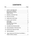
DIGITAL SOUND LEVEL
METER
USER’S MANUAL
DSM8930
Please read this manual carefully and thoroughly before using this product.
TABLE OF CONTENTS
Introduction . . . . . . . . . . . . . . . . . . . . . . . . . . . . . . 2 – 3
Key Features . . . . . . . . . . . . . . . . . . . . . . . . . . . . . . . . 3
What’s in the Blister Pack . . . . . . . . . . . . . . . . . . . . . . 4
Product Overview . . . . . . . . . . . . . . . . . . . . . . . . . . 4 – 5
Setup Instructions . . . . . . . . . . . . . . . . . . . . . . . . . . . . 6
Install Battery . . . . . . . . . . . . . . . . . . . . . . . . . . . . 6
Operating Instructions . . . . . . . . . . . . . . . . . . . . . . 6 – 8
Making Basic Measurements . . . . . . . . . . . . . 6 – 7
Tracking MIN and MAX Levels . . . . . . . . . . . . 7 – 8
Specifications . . . . . . . . . . . . . . . . . . . . . . . . . . . . . . . . 9
Maintenance Tips . . . . . . . . . . . . . . . . . . . . . . . . . . . . 10
Warranty Information . . . . . . . . . . . . . . . . . . . . . 10 – 11
Return for Repair Policy . . . . . . . . . . . . . . . . . . . . . . . 11
INTRODUCTION
Thank you for purchasing General Tools & Instruments’
DSM8930 Digital Sound Level Meter. Please read this user’s
manual carefully and thoroughly before using the instrument.
The DSM8930 uses an integrated condenser microphone to
measure the noise level of an environment or the loudness of
a machine, typically in order to comply with health and/or
safety rules. The meter has a measurement range of
40 to 130 dB over four ranges, an accuracy of ±2 dB,
2
and a digital display resolution of 0.1dB. Real-time
measurements are shown on a green backlit LCD in two
forms: as a three- or four-digit dB value, and as a moving
vertical line on a horizontal analog bar graph.
Several features improve the meter’s versatility. Among them
are “A” frequency weighting and “fast” (125 ms) time
response. The meter can display real-time readings or the
minimum or maximum sound levels measured since being
powered on.
Physical features of the DSM8930 include a wind shield ball
and an analog output jack for connecting to a chart recorder.
The DSM8930 is powered by one “9V” battery (included).
KEY FEATURES
• Measures sound level of a machine or an environment
• Meets IEC651 TYPE 2 and ANSI S1.4 TYPE 2 standards
• Large backlit LCD + analog bar graph
• “A” frequency weighting and fast time weighting
• Autoranging
• Tracks and displays maximum and minimum readings
• 20-minute Auto Power Off
• Analog output for chart recording
• Includes wind shield ball
• Powered by one “9V” battery (included)
3
WHAT’S IN THE BLISTER PACK
The DSM8930 comes fully assembled in a blister pack along
with a wind shield ball, one “9V” battery and this user’s
manual.
PRODUCT OVERVIEW
Figure 1 shows all of the controls, indicators and connectors
on the front, bottom and right side of the DSM8930. Figure 2
shows all text and icons that could appear on the LCD.
Familiarize yourself with the positions and functions of these
symbols and structures before moving on to the Setup
Instructions.
A
Fig. 1. The DSM8930’s controls,
display and connectors
A. Wind shield ball covering
Electret microphone
B. LCD
C.
(Power on/off),
MIN and MAX buttons
D. Battery compartment
E. Audio output jack
B
E
C
D
4
Fig. 2. All possible display indications and their meanings
MAX
Digital readout is highest level recorded since
meter was powered on
MIN
Digital readout is lowest level recorded since
meter was powered on
SPL
Abbreviation of sound pressure level (the
parameter measured)
Meter’s battery is very low on charge and should
be replaced
dB
Sound level unit (accompanies reading at its left)
40
Range Baseline (low end of current measurement
range, in dB). “40” indicates 40 to 70 dB range;
other possible numbers at this position are 60 (for
60 to 90 dB range), 80 (for 80 to 110 dB range)
and 100 (for 100 to 130 dB range)
+0, +10, Labels of analog bar graph scale. Indicate
+20, +30 amplitude of input (in dB) relative to low end of
measurement range above left end of graph
5
SETUP INSTRUCTIONS
INSTALL BATTERY
1. The meter’s battery compartment (Fig. 1, Callout D) is
accessible from the back of the unit near the bottom. Use a
Phillips-head screwdriver to loosen the screw holding the
yellow battery compartment cover in place. Set the cover
and screw aside.
2. Remove the “9V” battery from the blister pack and plug it
into the wired socket inside the compartment. The
terminals of the battery and the socket mate in only one
way, with the smaller male terminal plugging into the larger
female terminal.
3. Replace the battery compartment cover and tighten the
screw to secure it to the housing.
OPERATING INSTRUCTIONS
MAKING BASIC MEASUREMENTS
Press the button to power on the meter. The display will
take a few seconds to stabilize and then begin reading out
real-time sound level measurements.
Note how the digital numbers and the readings on the analog
bar graph track each other. At times, the two displays may
seem slightly out of sync—and they are, because they
refresh at different rates.
Also note how the number above the left end of the bar
graph—the Range Baseline—changes each time a much
louder or softer sound is heard. Each change confirms that
6
the meter is operating in Autoranging mode. To demonstrate
that autoranging is on in a quiet environment, rub the
windscreen with your hand (to simulate a loud noise) and
watch the Range Baseline change to 100 dB.
To measure the loudness of a sound source, point the
microphone at it. The measurement calculation reflects the
meter’s fixed settings: “A” frequency weighting and fast time
weighting. The shape of the “A” frequency-weighting curve
simulates the response of the human ear, so “A” weighting is
suitable for measuring the sound level of an environment for
the purpose of regulatory compliance, workplace design or
noise-pollution control. Fast time weighting, with a response
time (integration time constant) of 125 milliseconds, also
simulates the response time of the human ear and is most
suitable for measuring the volume of singular events.
If a sound level is below 40 dB, the readout will be LO. If a
sound level is above 130 dB, the readout will be HI.
TRACKING MIN AND MAX LEVELS
After being powered on, the DSM8930 automatically operates
in “Recording” mode for the purpose of tracking and
displaying minimum and maximum sound level
measurements.
To display the minimum sound level measured since the
meter was powered on, press the MIN button. The text MIN
will appear on the top line of the display and the digital
display will indicate the lowest sound volume measured since
power on. While the digital display is showing the minimum
sound value, the meter continues to measure real-time sound
level inputs and to display its results on the analog bar graph.
7
To display the maximum sound level measured since the
meter was powered on, press the MAX button. The text MAX
will replace MIN on the top line of the display and the digital
display will indicate the highest sound volume measured
since power on. While the digital display is showing the
maximum sound value, the meter continues to measure realtime sound level inputs and to display its results on the
analog bar graph.
To exit MIN or MAX display mode and return the digital display
to showing real-time values, press whichever button
corresponds to the current display mode. You cannot switch
from MIN to MAX mode by pushing the “opposite” button. You
must first exit one mode before entering the other.
By default, the meter powers off automatically after
20 minutes of inactivity by the end user (no front-panel
buttons are pushed) to extend the “9V” battery’s life. This
“APO” feature cannot be disabled. As a result, you cannot
track sound levels for longer than 20 minutes by feeding the
meter’s 0 to 0.707VAC analog output signal from the jack on
the right side of the meter (Fig. 1, Callout E) into a chart
recorder. However, 20 minutes is more than sufficient to
perform and document a typical sound-level check.
8
SPECIFICATIONS
Measurement Range
40 to 130 dB over four ranges
(40 to 70 dB, 60 to 90 dB,
80 to 110 dB, 100 to 130 dB)
Measurement Accuracy
±2 dB
Display Size/Type
4-digit (4000 count) LCD
Digital Display Resolution
0.1 dB
Digital Display Refresh Period 160 milliseconds
Analog Bar Graph Resolution 1 dB
Analog Bar Graph
40 milliseconds
Refresh Period
Frequency Range
100 Hz to 8.3 kHz
Time Weighting Time Constant 125 milliseconds
Microphone Diameter/Type 0.5 in. (12.7mm)
Electret condenser
Battery Life
30 hours (typical)
Analog Output
0 to 0.707VAC
Operating Temperature
32° to 122°F (0° to 50°C)
@<80% R.H.
Storage Temperature
-4° to 122°F (-20° to 50°C)
@<90% R.H.
Dimensions
8.1 x 2.4 x 1.6 in.
(210 x 61 x 40mm)
Weight
5.2 oz. (147g),
including battery
Power Source
(1) “9V” battery
9
MAINTENANCE TIPS
When the
icon appears at the upper right of the display,
it’s time to replace the “9V” battery that powers the
instrument (although measurements will remain valid for
several hours after the icon first appears). To replace the
battery, follow the instructions on p. 6.
Remove the battery when storing the meter and when you do
not expect to use it for an extended period of time (months
rather than weeks).
Do not drop or disassemble the meter or immerse it in water.
WARRANTY INFORMATION
General Tools & Instruments’ (General’s) DSM8930 Digital
Sound Level Meter is warranted to the original purchaser to
be free from defects in material and workmanship for a
period of one year. Subject to certain restrictions, General will
repair or replace this instrument if, after examination, the
company determines it to be defective in material or
workmanship.
This warranty does not apply to damages that General
determines to be from an attempted repair by non-authorized
personnel or misuse, alterations, normal wear and tear, or
accidental damage. The defective unit must be returned to
General Tools & Instruments or to a General-authorized
service center, freight prepaid and insured.
Acceptance of the exclusive repair and replacement remedies
described herein is a condition of the contract for purchase of
this product. In no event shall General be liable for any
incidental, special, consequential or punitive damages, or for
10
any cost, attorneys’ fees, expenses, or losses alleged to be a
consequence of damage due to failure of, or defect in any
product including, but not limited to, any claims for loss of
profits.
RETURN FOR REPAIR POLICY
Every effort has been made to provide you with a reliable
product of superior quality. However, in the event your
instrument requires repair, please contact our Customer
Service to obtain an RGA (Return Goods Authorization)
number before forwarding the unit via prepaid freight to the
attention of our Service Center at this address:
General Tools & Instruments
80 White Street
New York, NY 10013
212-431-6100
Remember to include a copy of your proof of purchase, your
return address, and your phone number and/or e-mail
address.
11
GENERAL TOOLS & INSTRUMENTS
80 White Street
New York, NY 10013-3567
PHONE (212) 431-6100
FAX (212) 431-6499
TOLL FREE (800) 697-8665
e-mail: [email protected]
www.generaltools.com
DSM8930 User’s Manual
Specifications subject to change without notice
©2012 GENERAL TOOLS & INSTRUMENTS
NOTICE - WE ARE NOT RESPONSIBLE FOR TYPOGRAPHICAL ERRORS.
MAN#DSM8930 8/16/12