1
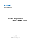
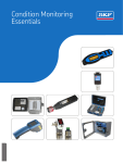
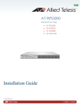
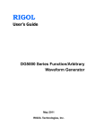
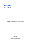
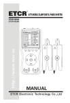
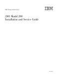
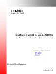
RIGOL User’s Guide RP7000 Series Active Probe Dec. 2013 RIGOL Technologies, Inc. RIGOL Guaranty and Declaration Copyright © 2011 RIGOL Technologies, Inc. All Rights Reserved. Trademark Information RIGOL is a registered trademark of RIGOL Technologies, Inc. Publication Number UGE07107-1110 Notices RIGOL products are protected by patent law in and outside of P.R.C. RIGOL reserves the right to modify or change parts of or all the specifications and pricing policies at company’s sole decision. Information in this publication replaces all previously corresponding materials. RIGOL shall not be liable for losses caused by either incidental or consequential in connection with the furnishing, use or performance of this manual as well as any information contained. Any part of this document is forbidden to be copied or photocopied or rearranged without prior written approval of RIGOL. Product Certification RIGOL guarantees this product conforms to the national and industrial standards in China as well as the ISO9001:2008 standard and the ISO14001:2004 standard. Other international standard conformance certification is in progress. Contact Us If you have any problem or requirement when using our products or this manual, please contact RIGOL Technologies, Inc. E-mail: [email protected] Website: www.rigol.com User’s Guide for RP7000 Series Active Probe I RIGOL Safety Terms and Symbols Terms in this Manual. The following terms may appear in this manual: WARNING Warning statements indicate the conditions or practices that could result in injuries or loss of life. CAUTION Caution statements indicate the conditions or practices that could result in damage to this product or loss of data. Terms on the Product. The following terms may appear on the product: DANGER indicates a hazard may immediately happen. WARNING indicates potential hazard may happen. CAUTION indicates damage to the instrument or other devices connected to the instrument may happen. Symbols on the Product. The following symbols may appear on the product: High Voltage II Safety Warning Protective Earth terminal Chassis Ground Test Ground User’s Guide for RP7000 Series Active Probe RIGOL Document Overview This document is used to guide users to get a quick understanding of the RP7000 series active probe as well as its using method. Besides, this document gives service information relating to general care and cleaning. RP7000 series active probe includes the following model. Model Bandwidth PR7150 >1.5GHz RP7080 >0.8GHz Main topics: RP7000 Series Overview This chapter gives a brief introduction of the probe, including general inspection, probe dimensions, standard accessories etc. To Use RP7000 Series Active Probe This chapter introduces how to use the probe, including how to connect to the oscilloscope, how to use the probe head, how to replace probe accessories, how to adjust the offset voltage, how to calibrate the probe etc. General Care and Cleaning Warranty Specifications User’s Guide for RP7000 Series Active Probe III RIGOL Contents Guaranty and Declaration .................................................................... I Safety Terms and Symbols ................................................................. II Document Overview .......................................................................... III RP7000 Series Overview ......................................................................1 Probe Introduction ............................................................................. 2 General Inspection ............................................................................. 3 Probe Dimensions .............................................................................. 4 Accessories and Options ..................................................................... 5 Active Probe Amplifier ........................................................................ 7 Probe Head ....................................................................................... 8 To Use RP7000 Series Active Probe .................................................. 12 To Connect to the Oscilloscope.......................................................... 13 To Use the Probe Head ..................................................................... 15 To Replace Probe Accessories ........................................................... 19 To Adjust Offset Voltage ................................................................... 21 To Calibrate the Probe ...................................................................... 22 General Care and Cleaning ................................................................ 24 Warranty ............................................................................................ 25 Specifications .................................................................................... 26 IV User’s Guide for RP7000 Series Active Probe RIGOL RP7000 Series Overview This chapter guides users to quickly get familiar with the RP7000 series active probe. Main topics: Probe Introduction General Inspection Probe Dimensions Accessories and Options Active Probe Amplifier Probe Head User’s Guide for RP7000 Series Active Probe 1 RIGOL Probe Introduction RP7000, with more than 1.5GHz bandwidth, is an active probe solution for high frequency application. It can be used to measure differential and single-ended signals with better common mode rejection. RP7000 uses plug-on socket probe head and supports 4 types of interchangeable probe heads to optimize the performance and usability. Besides, its replaceable probe tip prolongs the service life of the probe and the probe tip spacing can be precisely adjusted to fit different test point spacing. RP7000 is compatible with the auto-identification port of RIGOL DS6000/MSO4000/DS4000 series oscilloscope and can be recognized and configured automatically by this port. Its snap-in BNC connector enables easier connection with the oscilloscope. RP7000 provides various accessories and options and multiple replaceable components which make it applicable to be used in different tests and measurements. 2 User’s Guide for RP7000 Series Active Probe RIGOL General Inspection 1. Inspect the shipping container for damage. If your shipping container appears to be damaged, keep the shipping container or cushioning material until you have inspected the contents of the shipment for completeness and have checked the probe electrically and mechanically. If your probe has damaged during shipping, please contact your shipper and carrier for compensation. RIGOL will provide no free repair or replacement. 2. Inspect the probe. If there is any mechanical damage or defect, or if the probe does not pass electrical and mechanical tests, please contact your RIGOL sales representative. 3. Check the Accessories. Please check the accessories according to Accessories and Options in this guide. If the accessories are incomplete or damaged, please contact your RIGOL sales representative. User’s Guide for RP7000 Series Active Probe 3 RIGOL Probe Dimensions Figure 1 shows the dimensions of the main parts of RP7000 series active probe. Figure 1 Probe Dimensions 4 User’s Guide for RP7000 Series Active Probe RIGOL Accessories and Options This section lists the probe kits, standard accessories of the RP7000 series active probe respectively. All the components listed below can be ordered from RIGOL. RP7150 Active Probe Kit (the ordering number is RP7150) contains all the accessories listed in Table 1. If any accessory or option needs to be ordered separately, please refer to Table 1. RP7080 Active Probe Kit (the ordering number is RP7080) contains all the accessories listed in Table 2. If any accessory or option needs to be ordered separately, please refer toTable 2. Table 1 RP7150 Active Probe Kit (Ordering NO. is RP7150) Standard Accessories Name Ordering NO. Qty. PCK100 Active Differential Probe Calibration Kit PCK100 1 RP7150 Active Probe Amplifier RP7-0150 1 Solder-in Differential Probe Head RP7-0201 1 Solder-in Single-ended Probe Head RP7-0203 1 Hand-held Differential Probe Head RP7-0204 1 Hand-held Single-ended Probe Head RP7-0205 1 0.2mm Nickel Wire RP7-0306 1 Trim Gauge RP7-0307 1 91Ω Probe Tip RP7-0405 8 Straight Acuminate Ground Collar RP7-0501 2 Curved Acuminate Ground Collar RP7-0502 2 Straight Dentiform Ground Collar RP7-0503 2 Curved Dentiform Ground Collar RP7-0504 2 Marker Rings (Yellow/Pink/Light Blue/Dark Blue) RP-0203 8 User’s Guide RP7-0601 1 Probe Bag RP7-0602 1 Storage Box RP7-0603 1 User’s Guide for RP7000 Series Active Probe 5 RIGOL Table 2 RP7080 Active Probe Kit (Ordering NO. is RP7080) Standard Accessories Name Ordering NO. Qty. PCK100 Active Differential Probe Calibration Kit PCK100 1 RP7080 Active Probe Amplifier RP7-0080 1 Solder-in Differential Probe Head RP7-0201 1 Solder-in Single-ended Probe Head RP7-0203 1 Hand-held Differential Probe Head RP7-0204 1 Hand-held Single-ended Probe Head RP7-0205 1 0.2mm Nickel Wire RP7-0306 1 Trim Gauge RP7-0307 1 91Ω Probe Tip RP7-0405 8 Straight Acuminate Ground Collar RP7-0501 2 Curved Acuminate Ground Collar RP7-0502 2 Straight Dentiform Ground Collar RP7-0503 2 Curved Dentiform Ground Collar RP7-0504 2 Marker Rings (Yellow/Pink/Light Blue/Dark Blue) RP-0203 8 User’s Guide RP7-0601 1 Probe Bag RP7-0602 1 Storage Box RP7-0603 1 Note: the accessories listed in this section are only for reference, the actual product is the standard. 6 User’s Guide for RP7000 Series Active Probe RIGOL Active Probe Amplifier The active probe amplifier (Figure 2), with more than 1.5GHz bandwidth, is a main component of the active probe. One end of the active probe amplifier can be connected to the DS6000 series oscilloscope and the other end can be connected to the desired probe head. + - Pos/Neg Marker Figure 2 Active Probe Amplifier When connecting a probe head to an active probe amplifier, push it straight in. For single-ended probe, when connecting them, pay attention to their polarities. If the polarity is reversed, the performance of the active probe would reduce and the active probe might even be damaged. CAUTION There are Pos/Neg markers on the hand-held single-ended probe head and black mark sleeve on the negative pole of the solder-in single-ended probe head. User’s Guide for RP7000 Series Active Probe 7 RIGOL Probe Head RP7000 supports hand-held probe head and solder-in probe head. 1. Hand-held Probe Head Hand-held probe head includes two types: hand-held differential probe head and hand-held single-ended probe head. Like using common passive probes, you can use this kind of probe head to easily measure signals. Besides, the spacing between the probe tips can be easily adjusted to fulfill your various measurement requirements. For hand-held differential probe head, the spacing between the probe tips is controlled by the roller on the probe head. As shown in Figure 3, turning the roller forwards or backwards can precisely adjust the spacing between the two probe tips. Figure 3 Hand-held Differential Probe Head For hand-held single-ended probe head, rotating the single-ended ground collar adjusts the spacing between the single-ended ground collar and probe tip, as shown in Figure 4. 8 User’s Guide for RP7000 Series Active Probe RIGOL Figure 4 Hand-held Single-ended Probe Head Wherein, as shown in Figure 5 and Figure 6, probe tip and single-ended ground collar are standard accessories and are both replaceable. If any of them is damaged during use, you can easily replace it with a new one (refer to To Replace Probe Accessories). RP7000 provides 4 kinds of single-ended ground collars for different measurement requirements, the structures of the ground collars are as shown in Figure 6. a) Straight Acuminate Ground Collar: applicable to measurement of test point that is close to the ground point. b) Curved Acuminate Ground Collar: applicable to measurement of test point that is relatively far from the ground point. c) Straight Dentiform Ground Collar: applicable to measurement of chip pin test point that is close to the ground point. d) Curved Dentiform Ground Collar: applicable to measurement of chip pin test point that is relatively far from the ground point. User’s Guide for RP7000 Series Active Probe 9 RIGOL Figure 5 Probe Tip Figure 6 (b) Figure 6 (a) Straight Acuminate Ground Collar Figure 6 (d) Figure 6 (c) Straight Dentiform Ground Collar 10 Curved Acuminate Ground Collar Curved Dentiform Ground Collar User’s Guide for RP7000 Series Active Probe RIGOL 2. Solder-in Probe Head Solder-in probe head includes two types: solder-in differential probe head and solder-in single-ended probe head as shown in Figure 7 and Figure 8. Wherein, solder-in differential probe head is suitable for measurement of high-density IC pin signals. Nickel Wire Figure 7 Solder-in Differential Probe Head Nickel Wire Mark Sleeve of Negative Pole Figure 8 Solder-in Single-ended Probe Head When using the solder-in probe head for measurement, please use auxiliary device to fix the probe head. Do not use your hand to fix the probe head, or else, the lead resistor soldered onto the probe head might break or fall off, what’s more, the hand-held position might also affect the probe performance. Wherein, the nickel wire of the solder-in probe head is a standard accessory. If the nickel wire under use became damaged or break off, please replace it with an appropriate lead resistor (refer to To Replace Probe Accessories). User’s Guide for RP7000 Series Active Probe 11 RIGOL To Use RP7000 Series Active Probe During the use of RP7000 series active probe, correct operations can ensure the probe performance, prolong the service life of the probe and ensure the effectiveness of the signal measurement result. This chapter introduces in detail the using method of the RP7000 series active probe. Main Topics: To Connect to the Oscilloscope To Use the Probe Head To Replace Probe Accessories To Adjust Offset Voltage To Calibrate the Probe 12 User’s Guide for RP7000 Series Active Probe RIGOL To Connect to the Oscilloscope After RP7000 is connected correctly to a RIGOL DS6000 series oscilloscope, the oscilloscope recognizes the probe automatically and provides both power and offset voltage to the probe. You can adjust the offset voltage (refer to To Adjust Offset Voltage) and calibrate the probe (refer to To Calibrate the Probe) by the front panel menu of the oscilloscope. Please connect the probe to the oscilloscope following the steps below: 1. Connect the probe head (in the figure, taking a hand-held differential probe head for example) with the active probe amplifier. If single-ended probe head is used, during the connection, pay attention to their polarities. 2. Connect the other end of the active probe amplifier to the channel input or external trigger input connector of the oscilloscope and make sure the connection is tight. 3. Use any probe auxiliary device to connect the probe to the circuit to be User’s Guide for RP7000 Series Active Probe 13 RIGOL tested. 4. To disconnect the probe from the oscilloscope, press the button on the probe (as shown in the left figure below), pull the connector straight out of the oscilloscope (as shown in the right figure below) and then release the button. CAUTION Do not twist the probe on the BNC connector of the oscilloscope, or else, the probe might be damaged. 14 User’s Guide for RP7000 Series Active Probe RIGOL To Use the Probe Head Known from Probe Head, RP7000 can be connected with 4 kinds of probe heads. You can easily change the probe head by using the method introduced in To Replace Probe Accessories. This chapter introduces how to use the four kinds of probe heads respectively. 1. Hand-held Differential Probe Head The hand-held differential probe head provides an effective bandwidth of more than 1.5GHz. Besides, the spacing between the two probe tips can be precisely adjusted by turning the roller and the replaceable probe tips prolong the service life of the probe. The hand-held differential probe head can be used to measure differential and single-ended signals. During the measurement, you can turn the roller on the probe head to adjust the spacing between the probe tips so as to fit measurements with different spacing requirements. The structure of the hand-held differential probe head is as shown in Figure 9. ① ② ③ Figure 9 Hand-held Differential Probe Head User’s Guide for RP7000 Series Active Probe 15 RIGOL ① Turning the roller to adjust the spacing (0mm to 5.5mm) between the two probe tips. ② Hand-held differential probe head (RP7-0204). ③ 91Ω probe tip (RP7-0405). 2. Hand-held Single-ended Probe Head The hand-held single-ended probe head provides an effective bandwidth of more than 1.5GHz. Besides, the spacing between the single-ended ground collar and probe tip can be adjusted by rotating the ground collar and the replaceable probe tip and single-ended ground collar prolong the service life of the probe. The hand-held single-ended probe head can be used to measure single-ended signal. During the measurement, the single-ended ground collar must be grounded. Pay attention to their polarities when connecting the probe head and active probe amplifier. The structure of the hand-held single-ended probe head is as shown in Figure 10. ① ③ ② Figure 10 Hand-held Single-ended Probe Head 16 User’s Guide for RP7000 Series Active Probe RIGOL ① Hand-held single-ended probe head (RP7-0205). ② 91Ω probe tip (RP7-0405). ③ Straight acuminate ground collar: rotating the ground collar adjusts the spacing (0mm to 5mm) between the ground collar and probe tip (RP7-0501). CAUTION Ground the ground collar when using the hand-held single-ended probe. 3. Solder-in Differential Probe Head The solder-in differential probe head provides an effective bandwidth of more than 1.5GHz and its replaceable nickel wire enhance the usability of the probe and prolong its service life. The structure of the solder-in differential probe head is as shown in Figure 11. ① ② Figure 11 Solder-in Differential Probe Head User’s Guide for RP7000 Series Active Probe 17 RIGOL ① Solder-in differential probe head (RP7-0201). ② 0.2mm Nickel Wire (RP7-0306). When the points to be tested are widely spaced, the length of the nickel wire will be increased. At this point, overshoot and ringing will occurs and the high-frequency response will changes. 4. Solder-in Single-ended Probe Head The solder-in single-ended probe head provides an effective bandwidth of more than 1.5GHz and its replaceable nickel wire enhance the usability of the probe and prolong its service life. The structure of the solder-in single-ended probe head is as shown in Figure 12. The pin on the same side with the negative pole mark sleeve (refer to Figure 8) is negative. ① ② Figure 12 Solder-in Single-ended Probe Head 18 User’s Guide for RP7000 Series Active Probe RIGOL ① Solder-in single-ended probe head (RP7-0203). ② 0.2mm Nickel Wire (RP7-0306). When the points to be tested are widely spaced, the length of the nickel wire will be increased. At this point, overshoot and ringing will occurs and the high-frequency response will changes. To Replace Probe Accessories 1. To replace the probe head Take care not to damage the connecting part to avoid affecting the probe performance when replacing the probe head. Replacing Method: ① Disconnect the current probe head from the active probe amplifier. ② Push the new probe head into the active probe amplifier straightly. When single-ended probe head is used, pay attention to their polarities. 2. Replace the probe tip The probe tip and probe head are connected with screw thread, so please note the screw rotation and strength when removing and installing the probe tip. 3. Replace the single-ended ground collar Make sure the single-ended ground collar is firmly connected to the copper pipe to ensure the probe performance when replacing it. User’s Guide for RP7000 Series Active Probe 19 RIGOL 4. To replace the nickel wire If the nickel wire of the solder-in probe head under use become damaged or break off, you can replace a new one. The probe head nickel wire should satisfy the following size requirement, namely the length must be shorter than 5mm. <5mm Note: If the length of the nickel wire is longer than 5mm, the bandwidth specification of the probe will be effected. You can use the trim gauge (RP7-0307) to measure and cut the nickel wire. 20 User’s Guide for RP7000 Series Active Probe RIGOL To Adjust Offset Voltage RIGOL DS6000/MSO4000/DS4000 series oscilloscope can provide offset voltage to the RP7000 series active probe. The offset voltage adjusts the measured signal which exceeds the input dynamic range of the probe within an appropriate range to ensure the measured signal’s integrity. You can adjust the offset voltage by operating the front panel menu of the oscilloscope and the operation method is as shown below. 1. Connect the RP7000 series active probe to the channel input terminal (such as CH1) of the DS6000/MSO4000/DS4000 oscilloscope, referring to To Connect to the Oscilloscope. 2. Open the probe offset voltage control menu of the DS6000/MSO4000/DS4000 oscilloscope (front panel operation: CH1 Probe Bias Voltage) and rotate the knob to adjust the value. User’s Guide for RP7000 Series Active Probe 21 RIGOL To Calibrate the Probe Before using, you can use the PCK1000 active differential probe calibration kit to calibrate the RP7000 series active probe.Follow the procedures below to calibrate the RP7000 active probe using this kit: 1. Connect one connector to the calibration board and the female BNC of the cable respectively and then connect the other connector to the other part of the calibration board (called part 1). 2. Connect the RP7000 active probe to the analog channel (CH1 to CH4 of the oscilloscope, illustrations here are based on CH1). 3. Open the probe calibration control menu (front panel operation: CH1 Probe Probe-Cal). At this point, calibration prompt message is displayed in the user interface of the oscilloscope. Follow the prompt message to connect part 1 to the oscilloscope. Generally, connect the BNC (male) of the connector to the corresponding analog channel and the male BNC of the cable to the [Trig Out/Calibration] port at the rear panel of the oscilloscope. 4. Adjust the spacing between the probe tips so as to connect the positive probe tip to the middle signal line on the calibration board and the negative probe tip to the both sides of the middle signal line. Note: it is recommended to place the probe tips at the middle of the calibration board. 5. 22 Press Start and the oscilloscope starts to calibrate the probe. The User’s Guide for RP7000 Series Active Probe RIGOL calibration will last for about 40 to 50 seconds. When probe calibration finished, “Probe calibration finished!” or “Probe calibration failure!” is displayed in the user interface of the oscilloscope. Note: to ensure the calibration precision, the probe tips must be firmly connected to the calibration board during the calibration. Note: Relative specifications of the RP7000 series active probe depend on the calibration operation. After the calibration is finished, the DC gain, offset voltage zero and offset gain will be calibrated. User can query the information about the manufacturer, model, serial number and the last calibration time of the probe through CH1 Probe Probe Info. User’s Guide for RP7000 Series Active Probe 23 RIGOL General Care and Cleaning General Care: Do not place the probe and its accessories in places where they will be exposed to sun light for long periods of time. CAUTION Keep the probe and its accessories away from any corrosive liquid. Cleaning: Clean the probe and its accessories regularly according to their operation conditions using the method below. 1. Disconnect the probe from the oscilloscope or voltage source. 2. Remove the loose dust on the exterior of the probe and its accessories using a lint-free cloth (with mild detergent or water). WARNING Make sure the probe is completely dry before using it to avoid short circuit and personal injuries. 24 User’s Guide for RP7000 Series Active Probe RIGOL Warranty RIGOL warrants that its products mainframe and accessories will be free from defects in materials and workmanship within the warranty period. If a product is proven to be defective within the respective period, RIGOL guarantees the free replacement or repair of products which are approved defective. For detailed warranty description, please refer to RIGOL official website or the warranty card. To get repair service or a complete copy of the warranty description, please contact with your nearest RIGOL sales and service office. RIGOL does not provide any other warranty items except the one being provided by this summary and the warranty statement. The warranty items include but not being subjected to the hint guarantee items related to tradable characteristic and any particular purpose. RIGOL will not take any responsibility in cases regarding to indirect, particular and ensuing damage. User’s Guide for RP7000 Series Active Probe 25 RIGOL Specifications Technical Specifications Item RP7150 RP7080 Bandwidth >1.5GHz >0.8GHz Rise Time <265ps <465ps System Bandwidth 1GHz (DS6104 or 0.8GHz (DS6104 or DS6102) DS6102) Input Capacitance <1pF Input Resistance 50kΩ±2% Differential 25kΩ±4% Single-ended Input Dynamic Range ±6.25V Input Common mode ±6.75V DC to 100Hz Range ±1.25V >100Hz Common Mode >45dB@1MHz Rejection Ratio DC Attenuation 10:1 ±2% [1] Zero Offset Error Offset Voltage Range <30mV before calibration <5mV after calibration ±12V <3% of current range Offset Accuracy[1] before calibration <1% of current range after calibration Input Noise 45mVpp Propagation Delay 7ns Max Input Voltage 30V Peak CAT I[2] Electrostatic Protection >8kV 26 User’s Guide for RP7000 Series Active Probe RIGOL General Characteristics Environmental Operating Non-operating Temperature +5°C to +40°C -40°C to +70°C Humidity 0 RH to 80% RH 0 RH to 90% RH Altitude 4600m 15300m Power Consumption 1.2W N/A Weights 147g±10g[3] 530g±50g[4] Wire Length 1.4m Conditions [1] Typical value. The specifications would change when different scales are selected. [2] CAT I and CAT II Definitions Installation Category (Overvoltage Category) I: signal level, special equipment or parts of equipment, telecommunication, electronic, etc., with smaller transient voltages than installation category (Overvoltage Category) II. Installation Category (Overvoltage Category) II: local level, appliance, portable equipment etc., with smaller transient voltages than installation category (Overvoltage Category) III. [3] The weight of the probe with the hand-held differential probe head. [4] The weight of the RP7000 series Active Probe Kit with the probe bag. User’s Guide for RP7000 Series Active Probe 27