Download CPM1A Programmable Controllers Operation Manual
Transcript
CPM1A Programmable Controllers Operation Manual Revised August 1999 iv Notice: OMRON products are manufactured for use according to proper procedures by a qualified operator and only for the purposes described in this manual. The following conventions are used to indicate and classify precautions in this manual. Always heed the information provided with them. Failure to heed precautions can result in injury to people or damage to property. DANGER Indicates an imminently hazardous situation which, if not avoided, will result in death or serious injury. ! WARNING Indicates a potentially hazardous situation which, if not avoided, could result in death or serious injury. ! Caution Indicates a potentially hazardous situation which, if not avoided, may result in minor or moderate injury, or property damage. ! OMRON Product References All OMRON products are capitalized in this manual. The word “Unit” is also capitalized when it refers to an OMRON product, regardless of whether or not it appears in the proper name of the product. The abbreviation “Ch,” which appears in some displays and on some OMRON products, often means “word” and is abbreviated “Wd” in documentation in this sense. The abbreviation “PC” means Programmable Controller and is not used as an abbreviation for anything else. Visual Aids The following headings appear in the left column of the manual to help you locate different types of information. Note Indicates information of particular interest for efficient and convenient operation of the product. 1, 2, 3... 1. Indicates lists of one sort or another, such as procedures, checklists, etc. OMRON, 1997 All rights reserved. No part of this publication may be reproduced, stored in a retrieval system, or transmitted, in any form, or by any means, mechanical, electronic, photocopying, recording, or otherwise, without the prior written permission of OMRON. No patent liability is assumed with respect to the use of the information contained herein. Moreover, because OMRON is constantly striving to improve its high-quality products, the information contained in this manual is subject to change without notice. Every precaution has been taken in the preparation of this manual. Nevertheless, OMRON assumes no responsibility for errors or omissions. Neither is any liability assumed for damages resulting from the use of the information contained in this publication. v vi TABLE OF CONTENTS PRECAUTIONS . . . . . . . . . . . . . . . . . . . . . . . . . . . . . . . . . 1 Intended Audience . . . . . . . . . . . . . . . . . . . . . . . . . . . . . . . . . . . . . . . . . . . . . . . . . . . . . . . . . . . 2 General Precautions . . . . . . . . . . . . . . . . . . . . . . . . . . . . . . . . . . . . . . . . . . . . . . . . . . . . . . . . . . 3 Safety Precautions . . . . . . . . . . . . . . . . . . . . . . . . . . . . . . . . . . . . . . . . . . . . . . . . . . . . . . . . . . . 4 Operating Environment Precautions . . . . . . . . . . . . . . . . . . . . . . . . . . . . . . . . . . . . . . . . . . . . . 5 Application Precautions . . . . . . . . . . . . . . . . . . . . . . . . . . . . . . . . . . . . . . . . . . . . . . . . . . . . . . 6 EC Directives . . . . . . . . . . . . . . . . . . . . . . . . . . . . . . . . . . . . . . . . . . . . . . . . . . . . . . . . . . . . . . SECTION 1 Introduction . . . . . . . . . . . . . . . . . . . . . . . . . . . . . . . . . . . . 1-1 1-2 1-3 CPM1A Features and Functions . . . . . . . . . . . . . . . . . . . . . . . . . . . . . . . . . . . . . . . . . . . . System Configuration . . . . . . . . . . . . . . . . . . . . . . . . . . . . . . . . . . . . . . . . . . . . . . . . . . . . . Revised Specifications . . . . . . . . . . . . . . . . . . . . . . . . . . . . . . . . . . . . . . . . . . . . . . . . . . . . SECTION 2 Unit Specifications and Components . . . . . . . . . . . . . . . . 2-1 2-2 Specifications . . . . . . . . . . . . . . . . . . . . . . . . . . . . . . . . . . . . . . . . . . . . . . . . . . . . . . . . . . . Unit Components . . . . . . . . . . . . . . . . . . . . . . . . . . . . . . . . . . . . . . . . . . . . . . . . . . . . . . . . SECTION 3 Installation and Wiring . . . . . . . . . . . . . . . . . . . . . . . . . . . 3-1 3-2 3-3 3-4 Design Precautions . . . . . . . . . . . . . . . . . . . . . . . . . . . . . . . . . . . . . . . . . . . . . . . . . . . . . . . Selecting an Installation Site . . . . . . . . . . . . . . . . . . . . . . . . . . . . . . . . . . . . . . . . . . . . . . . Installing the CPM1A . . . . . . . . . . . . . . . . . . . . . . . . . . . . . . . . . . . . . . . . . . . . . . . . . . . . . Wiring and Connections . . . . . . . . . . . . . . . . . . . . . . . . . . . . . . . . . . . . . . . . . . . . . . . . . . . SECTION 4 Using Peripheral Devices . . . . . . . . . . . . . . . . . . . . . . . . . . 4-1 4-2 4-3 4-4 Support Software Capabilities . . . . . . . . . . . . . . . . . . . . . . . . . . . . . . . . . . . . . . . . . . . . . . Using a Programming Console . . . . . . . . . . . . . . . . . . . . . . . . . . . . . . . . . . . . . . . . . . . . . Programming Console Operations . . . . . . . . . . . . . . . . . . . . . . . . . . . . . . . . . . . . . . . . . . . Programming Example . . . . . . . . . . . . . . . . . . . . . . . . . . . . . . . . . . . . . . . . . . . . . . . . . . . . SECTION 5 Test Runs and Error Processing . . . . . . . . . . . . . . . . . . . . 5-1 5-2 5-3 5-4 5-5 5-6 5-7 5-8 Initial System Checks and Test Run Procedure . . . . . . . . . . . . . . . . . . . . . . . . . . . . . . . . . The CPM1A Cycle . . . . . . . . . . . . . . . . . . . . . . . . . . . . . . . . . . . . . . . . . . . . . . . . . . . . . . . Self-diagnosis Functions . . . . . . . . . . . . . . . . . . . . . . . . . . . . . . . . . . . . . . . . . . . . . . . . . . Programming Console Operation Errors . . . . . . . . . . . . . . . . . . . . . . . . . . . . . . . . . . . . . . Programming Errors . . . . . . . . . . . . . . . . . . . . . . . . . . . . . . . . . . . . . . . . . . . . . . . . . . . . . . Troubleshooting Flowcharts . . . . . . . . . . . . . . . . . . . . . . . . . . . . . . . . . . . . . . . . . . . . . . . . Maintenance Inspections . . . . . . . . . . . . . . . . . . . . . . . . . . . . . . . . . . . . . . . . . . . . . . . . . . Handling Precautions . . . . . . . . . . . . . . . . . . . . . . . . . . . . . . . . . . . . . . . . . . . . . . . . . . . . . xi xii xii xii xiii xiii xvi 1 2 9 16 17 18 25 33 34 35 37 40 65 66 71 77 98 105 106 108 109 111 111 113 121 122 Appendices A Standard Models . . . . . . . . . . . . . . . . . . . . . . . . . . . . . . . . . . . . . . . . . . . . . . . . . . . . . . . . . . . B Dimensions . . . . . . . . . . . . . . . . . . . . . . . . . . . . . . . . . . . . . . . . . . . . . . . . . . . . . . . . . . . . . . . . Glossary . . . . . . . . . . . . . . . . . . . . . . . . . . . . . . . . . . . . . . . Index . . . . . . . . . . . . . . . . . . . . . . . . . . . . . . . . . . . . . . . . . . Revision History . . . . . . . . . . . . . . . . . . . . . . . . . . . . . . . . . 123 125 131 147 151 vii About this Manual: The CPM1A is a compact, high-speed Programmable Controller (PC) designed for control operations in systems requiring from 10 to 100 I/O points per PC. There are two manuals describing the setup and operation of the CPM1A: the CPM1A Operation Manual (this manual) and the CPM1/CPM1A/CPM2A/ CPM2C/SRM1(-V2) Programming Manual (W353). This manual describes the system configuration and installation of the CPM1A and provides a basic explanation of operating procedures for the Programming Consoles. It also introduces the capabilities of the SYSMAC Support Software (SSS). Read this manual first to acquaint yourself with the CPM1A. The CPM1/CPM1A/CPM2A/CPM2C/SRM1(-V2) Programming Manual (W353) provides detailed descriptions of the CPM1A’s programming functions. The SYSMAC Support Software Operation Manuals: Basics and C-series PCs (W247 and W248) provide descriptions of SSS operations for the CPM1A and other SYSMAC C-series PCs. The SYSMAC-CPT Support Software Quick Start Guide (W332) and User Manual (W333) provide descriptions of ladder diagram operations in the Windows environment. Please read this manual carefully and be sure you understand the information provide before attempting to install and operate the CPM1A. Section 1 gives a brief overview of the steps involved in developing of a CPM1A System, describes the possible system configurations, and describes the CPM1A’s special features and functions. Section 2 provides the technical specifications of the Units that go together to create a CPM1A PC and describes the main components of the Units. Section 3 describes how to install and wire a CPM1A PC. Section 4 describes SSS capabilities, how to connect the Programming Console, and how to perform the various Programming Console operations. Section 5 describes how to perform a test run and how to diagnose and correct the hardware and software errors that can occur during PC operation. Appendix A provides tables of CPM1A Units and related products. Appendix B provides the dimensions of CPM1A Units. ! WARNING Failure to read and understand the information provided in this manual may result in personal injury or death, damage to the product, or product failure. Please read each section in its entirety and be sure you understand the information provided in the section and related sections before attempting any of the procedures or operations given. ix PRECAUTIONS This section provides general precautions for using the Programmable Controller (PC) and related devices. The information contained in this section is important for the safe and reliable application of the Programmable Controller. You must read this section and understand the information contained before attempting to set up or operate a PC system. 1 Intended Audience . . . . . . . . . . . . . . . . . . . . . . . . . . . . . . . . . . . . . . . . . . . . . . . . . . . . . . . . . . . . 2 General Precautions . . . . . . . . . . . . . . . . . . . . . . . . . . . . . . . . . . . . . . . . . . . . . . . . . . . . . . . . . . . 3 Safety Precautions . . . . . . . . . . . . . . . . . . . . . . . . . . . . . . . . . . . . . . . . . . . . . . . . . . . . . . . . . . . . 4 Operating Environment Precautions . . . . . . . . . . . . . . . . . . . . . . . . . . . . . . . . . . . . . . . . . . . . . . 5 Application Precautions . . . . . . . . . . . . . . . . . . . . . . . . . . . . . . . . . . . . . . . . . . . . . . . . . . . . . . . . 6 EC Directives . . . . . . . . . . . . . . . . . . . . . . . . . . . . . . . . . . . . . . . . . . . . . . . . . . . . . . . . . . . . . . . . xii xii xii xiii xiii xvi xi 3 Safety Precautions 1 Intended Audience This manual is intended for the following personnel, who must also have knowledge of electrical systems (an electrical engineer or the equivalent). • Personnel in charge of installing FA systems. • Personnel in charge of designing FA systems. • Personnel in charge of managing FA systems and facilities. 2 General Precautions The user must operate the product according to the performance specifications described in the operation manuals. Before using the product under conditions which are not described in the manual or applying the product to nuclear control systems, railroad systems, aviation systems, vehicles, combustion systems, medical equipment, amusement machines, safety equipment, and other systems, machines, and equipment that may have a serious influence on lives and property if used improperly, consult your OMRON representative. Make sure that the ratings and performance characteristics of the product are sufficient for the systems, machines, and equipment, and be sure to provide the systems, machines, and equipment with double safety mechanisms. This manual provides information for programming and operating the Unit. Be sure to read this manual before attempting to use the Unit and keep this manual close at hand for reference during operation. ! WARNING It is extremely important that a PC and all PC Units be used for the specified purpose and under the specified conditions, especially in applications that can directly or indirectly affect human life. You must consult with your OMRON representative before applying a PC System to the above-mentioned applications. 3 Safety Precautions ! WARNING Do not attempt to take any Unit apart while the power is being supplied. Doing so may result in electric shock. ! WARNING Do not touch any of the terminals or terminal blocks while the power is being supplied. Doing so may result in electric shock. ! WARNING Do not attempt to disassemble, repair, or modify any Units. Any attempt to do so may result in malfunction, fire, or electric shock. ! WARNING Provide safety measures in external circuits (i.e., not in the Programmable Controller), including the following items, in order to ensure safety in the system if an abnormality occurs due to malfunction of the PC or another external factor affecting the PC operation. Not doing so may result in serious accidents. • Emergency stop circuits, interlock circuits, limit circuits, and similar safety measures must be provided in external control circuits. • The PC will turn OFF all outputs when its self-diagnosis function detects any error or when a severe failure alarm (FALS) instruction is executed. As a countermeasure for such errors, external safety measures must be provided to ensure safety in the system. xii 5 Application Precautions • The PC outputs may remain ON or OFF due to deposition or burning of the output relays or destruction of the output transistors. As a countermeasure for such problems, external safety measures must be provided to ensure safety in the system. • When the 24-VDC output (service power supply to the PC) is overloaded or short-circuited, the voltage may drop and result in the outputs being turned OFF. As a countermeasure for such problems, external safety measures must be provided to ensure safety in the system. ! WARNING When transferring programs to other nodes, or when making changes to I/O memory, confirm the safety of the destination node before transfer. Not doing so may result in injury. 4 ! Caution Execute online edit only after confirming that no adverse effects will be caused by extending the cycle time. Otherwise, the input signals may not be readable. ! Caution Tighten the screws on the terminal block of the AC Power Supply Unit to the torque specified in the operation manual. The loose screws may result in burning or malfunction. Operating Environment Precautions ! Caution Do not operate the control system in the following places: • Locations subject to direct sunlight. • Locations subject to temperatures or humidity outside the range specified in the specifications. • Locations subject to condensation as the result of severe changes in temperature. • Locations subject to corrosive or flammable gases. • Locations subject to dust (especially iron dust) or salts. • Locations subject to exposure to water, oil, or chemicals. • Locations subject to shock or vibration. ! Caution Take appropriate and sufficient countermeasures when installing systems in the following locations: • Locations subject to static electricity or other forms of noise. • Locations subject to strong electromagnetic fields. • Locations subject to possible exposure to radioactivity. • Locations close to power supplies. ! Caution 5 The operating environment of the PC System can have a large effect on the longevity and reliability of the system. Improper operating environments can lead to malfunction, failure, and other unforeseeable problems with the PC System. Be sure that the operating environment is within the specified conditions at installation and remains within the specified conditions during the life of the system. Application Precautions Observe the following precautions when using the PC System. ! WARNING Always heed these precautions. Failure to abide by the following precautions could lead to serious or possibly fatal injury. xiii Application Precautions 5 • Always connect to a class-3 ground (to 100 Ω or less) when installing the Units. Not connecting to a class-3 ground may result in electric shock. • Always turn off the power supply to the PC before attempting any of the following. Not turning off the power supply may result in malfunction or electric shock. • Mounting or dismounting I/O Units, CPU Units, Memory Cassettes, or any other Units. • Assembling the Units. • Connecting or wiring the cables. • Connecting or disconnecting the connectors. ! Caution Failure to abide by the following precautions could lead to faulty operation of the PC or the system, or could damage the PC or PC Units. Always heed these precautions. • Fail-safe measures must be taken by the customer to ensure safety in the event of incorrect, missing, or abnormal signals caused by broken signal lines, momentary power interruptions, or other causes. • Construct a control circuit so that power supply for the I/O circuits does not come ON before power supply for the Unit. If power supply for the I/O circuits comes ON before power supply for the Unit, normal operation may be temporarily interrupted. • If the operating mode is changed from RUN or MONITOR mode to PROGRAM mode, with the IOM Hold Bit ON, the output will hold the most recent status. In such a case, ensure that the external load does not exceed specifications. (If operation is stopped because of an operation error (including FALS instructions), the values in the internal memory of the CPU Unit will be saved, but the outputs will all turn OFF.) • Always use the power supply voltage specified in the operation manuals. An incorrect voltage may result in malfunction or burning. • Take appropriate measures to ensure that the specified power with the rated voltage and frequency is supplied. Be particularly careful in places where the power supply is unstable. An incorrect power supply may result in malfunction. • Install external breakers and take other safety measures against short-circuiting in external wiring. Insufficient safety measures against short-circuiting may result in burning. • Do not apply voltages to the Input Units in excess of the rated input voltage. Excess voltages may result in burning. • Do not apply voltages or connect loads to the Output Units in excess of the maximum switching capacity. Excess voltage or loads may result in burning. • Disconnect the functional ground terminal when performing withstand voltage tests. Not disconnecting the functional ground terminal may result in burning. • Install the Unit properly as specified in the operation manual. Improper installation of the Unit may result in malfunction. • Be sure that all the mounting screws, terminal screws, and cable connector screws are tightened to the torque specified in the relevant manuals. Incorrect tightening torque may result in malfunction. • Be sure to attach the supplied labels when wiring in order to prevent wiring cuttings from entering in the Unit. • Remove the label after the completion of wiring to ensure proper heat dissipation. Leaving the label attached may result in malfunction. • Use crimp terminals for wiring. Do not connect bare stranded wires directly to terminals. Connection of bare stranded wires may result in burning. xiv 5 Application Precautions • Double-check all the wiring before turning on the power supply. Incorrect wiring may result in burning. • Mount the Unit only after checking the terminal block completely. • Be sure that the terminal blocks, Memory Units, expansion cables, and other items with locking devices are properly locked into place. Improper locking may result in malfunction. • Check the user program for proper execution before actually running it on the Unit. Not checking the program may result in an unexpected operation. • Confirm that no adverse effect will occur in the system before attempting any of the following. Not doing so may result in an unexpected operation. • Changing the operating mode of the PC. • Force-setting/force-resetting any bit in memory. • Changing the present value of any word or any set value in memory. • Resume operation only after transferring to the new CPU Unit the contents of the DM and HR Areas required for resuming operation. Not doing so may result in an unexpected operation. • Do not pull on the cables or bend the cables beyond their natural limit. Doing either of these may break the cables. • Do not place objects on top of the cables. Doing so may break the cables. • When replacing parts, be sure to confirm that the rating of a new part is correct. Not doing so may result in malfunction or burning. • Before touching the Unit, be sure to first touch a grounded metallic object in order to discharge any static built-up. Not doing so may result in malfunction or damage. • Do not touch the Expansion I/O Unit Connecting Cable while the power is being supplied in order to prevent any malfunction due to static electricity. ! Caution Always clear memory before beginning to program the CPM1A. Although memory is cleared before the CPU Unit is shipped (except for bits with specific functions), AR 1314, which turns ON when the internal capacitor cannot back up memory, may have turned ON during shipment. ! Caution If the CPM1A will be turned off for periods exceeding the data backup period of the internal capacitor, design the system so that it will not be influenced if data in the DM, HR, and CNT areas is cleared when power is turned off. ! Caution Either switch the CPM1A to RUN or MONITOR mode, or turn off and on power to the CPM1A after changing from a Programming Device any data that is backed up in flash memory. This data includes the user program, read-only DM area (DM 6144 to DM 6599), and the PC Setup (DM 6600 to DM 6655). • The user program and memory area data in the CPM1A are backed up either by an internal capacitor or in flash memory as shown in the following table. Backup method Internal capacitor Data Read/write DM area (DM 0000 to DM 0999, DM 1022, and DM 1023) Error log area (DM 1000 to DM 1021) HR area (HR 00 to HR 19) Counter area (CNT 000 to CNT 127) Flash memory User program Read-only DM area (DM 6144 to DM 6599) PC Setup (DM 6600 to DM 6655) xv 6 EC Directives 1. The IR, TR, LR, and timer areas are not normally backed up when power is turned off and all contents will be cleared the next time power is turned on. (The PC Setup setting in DM 6601 can be used to back up this data. Refer to details on the PC Setup later in this manual for details.) 2. The bits in the AR and SR areas have special functions and are set according to these functions when power is turned on. • The capacitor backup time depends on the ambient temperature, as shown in the following graph. The backup time, however, assumes that the capacitor is fully charged, which requires that power be supplied to the CPU Unit continuously for at least 15 minutes. Backup time (days) Note 20 10 7 1 25 40 80 Ambient temperature (C) If the power remains off for a period exceeding the data backup period, AR 1314 will turn ON to indicate that the capacitor can no longer back up data and the data backed up by the capacitor will be cleared. AR 1314 will remain ON unless it is turned OFF using I/O monitor operations, using memory clear operations, or from the user program. If desired, the PC Setup setting in DM 6604 can be set to create a fatal error and thus stop the system when AR 1314 goes ON. • The data stored in flash memory will not be lost even if power remains off for a period exceeding the data backup period, because the data stored in flash memory will be read to the CPU Unit when the CPM1A is turned on. • If the power is turned off without changing the mode from PROGRAM mode to RUN or MONITOR mode after having made changes in the data that is backed up in flash memory, the changes will not be written to flash memory. If the power is then left off for more than 20 days (at 25C), the changes (i.e., the contents of the RAM) will be erased and the data values will become undefined. 6 EC Directives 6-1 Applicable Directives • EMC Directives • Low Voltage Directive 6-2 Concepts EMC Directives OMRON devices that comply with EC Directives also conform to the related EMC standards so that they can be more easily built into other devices or the overall machine. The actual products have been checked for conformity to EMC standards (see the following note). Whether the products conform to the standards in the system used by the customer, however, must be checked by the customer. xvi 6 EC Directives EMC-related performance of the OMRON devices that comply with EC Directives will vary depending on the configuration, wiring, and other conditions of the equipment or control panel on which the OMRON devices are installed. The customer must, therefore, perform the final check to confirm that devices and the overall machine conform to EMC standards. Note Applicable EMC (Electromagnetic Compatibility) standards are as follows: EMS (Electromagnetic Susceptibility): EN61131-2 EMI (Electromagnetic Interference): EN50081-2 (Radiated emission: 10-m regulations) Low Voltage Directive Always ensure that devices operating at voltages of 50 to 1,000 VAC and 75 to 1,500 VDC meet the required safety standards for the PC (EN61131-2). 6-3 Conformance to EC Directives The CPM1A PCs (transistor output models) comply with EC Directives. Relay output models do not conform to the EC Directives. To ensure that the machine or device in which the CPM1A PC is used complies with EC directives, the PC must be installed as follows: 1, 2, 3... 1. The CPM1A PC must be installed within a control panel. 2. Reinforced insulation or double insulation must be used for the DC power supplies used for the communications and I/O power supplies. 3. CPM1A PCs complying with EC Directives also conform to the Common Emission Standard (EN50081-2). Radiated emission characteristics (10-m regulations) may vary depending on the configuration of the control panel used, other devices connected to the control panel, wiring, and other conditions. You must therefore confirm that the overall machine or equipment complies with EC Directives. 4. The CPM1A with relay output does not conform to the EC Directives. For devices for use in the EC, use the CPM1, which meets the CE marking requirements. Further information is available at any of the OMRON offices or OMRON sales representatives listed on the inside back cover of this manual. 6-4 CPM1A-MAD01 Conformance to EMC Directives Immunity testing conditions when using the current I/O of the CPM1A-MAD01 are as follows. • Total accuracy: +10%/-1% • Insert the following core in each line as shown below. Recommended core: 2643-002402 Manufacturer: Fair Rite Products Corp. xvii SECTION 1 Introduction This section describes the CPM1A’s special features and functions and shows the possible system configurations. Refer to the Programming Manual (W353) for details on programming actual operation. 1-1 1-2 1-3 CPM1A Features and Functions . . . . . . . . . . . . . . . . . . . . . . . . . . . . . . . . . . . . . . . . . . . . . 1-1-1 CPM1A Features . . . . . . . . . . . . . . . . . . . . . . . . . . . . . . . . . . . . . . . . . . . . . . . . . . 1-1-2 I/O Terminal and IR Bit Allocation . . . . . . . . . . . . . . . . . . . . . . . . . . . . . . . . . . . . 1-1-3 CPM1A Functions . . . . . . . . . . . . . . . . . . . . . . . . . . . . . . . . . . . . . . . . . . . . . . . . . System Configuration . . . . . . . . . . . . . . . . . . . . . . . . . . . . . . . . . . . . . . . . . . . . . . . . . . . . . . 1-2-1 CPU Unit and Expansion I/O Unit Configuration . . . . . . . . . . . . . . . . . . . . . . . . . 1-2-2 CPU Unit and Expansion Unit . . . . . . . . . . . . . . . . . . . . . . . . . . . . . . . . . . . . . . . . 1-2-3 Host Link Communications . . . . . . . . . . . . . . . . . . . . . . . . . . . . . . . . . . . . . . . . . . 1-2-4 One-to-one PC Link Communications . . . . . . . . . . . . . . . . . . . . . . . . . . . . . . . . . 1-2-5 One-to-one NT Link Communications . . . . . . . . . . . . . . . . . . . . . . . . . . . . . . . . . 1-2-6 CompoBus/S I/O Link Connections . . . . . . . . . . . . . . . . . . . . . . . . . . . . . . . . . . . 1-2-7 Peripheral Device Connections . . . . . . . . . . . . . . . . . . . . . . . . . . . . . . . . . . . . . . . Revised Specifications . . . . . . . . . . . . . . . . . . . . . . . . . . . . . . . . . . . . . . . . . . . . . . . . . . . . . 2 2 4 4 9 9 10 11 13 14 14 14 16 1 Section 1-1 CPM1A Features and Functions 1-1 CPM1A Features and Functions 1-1-1 CPM1A Features One-piece Construction The CPM1A CPU Units feature a one-piece construction including 10, 20, 30, or 40 built-in I/O terminals. The following three model groups are available: relay output models, sink-type transistor output models, and source-type transistor output models. CPM1A-10CDR-/10CDT-D/10CDT1-D (10 I/O terminals) CPM1A-20CDR-/20CDT-D/20CDT1-D (20 I/O terminals) CPM1A-30CDR-/30CDT-D/30CDT1-D (30 I/O terminals) CPM1A-40CDR-/40CDT-D/40CDT1-D (40 I/O terminals) Extra I/O Capacity Up to three Expansion I/O Units can be connected to a CPM1A-30CDR-/ 30CDT-D/30CDT1-D or CPM1A-40CDR-/40CDT-D/40CDT1-D CPU Unit to add an extra 8 or 20 I/O points for each, for a maximum of up to 100 I/O points. Input Filter Function The CPM1A is equipped with a filter function to prevent incorrect operation caused by chatter or noise in the input signal. The user can select an input time constant of 1 ms, 2 ms, 4 ms, 8 ms, 16 ms, 32 ms, 64 ms, or 128 ms. Low-maintenance Design Flash memory provides memory backup without a battery. Input Interrupts The CPM1A-10CDR-/10CDT-D/10CDT1-D CPU Units can handle 2 interrupt inputs; the CPM1A-20CDR-/20CDT-D/20CDT1-D, CPM1A-30CDR-/ 30CDT-D/30CDT1-D, and CPM1A-40CDR-/40CDT-D/40CDT1-D CPU Units can handle 4 interrupt inputs. In addition to normal input interrupts, the CPM1A has a counter mode that counts high-speed input signals and triggers interrupts at fixed count multiples. Quick-response Inputs Quick-response inputs can detect input signals with a pulse width as short as 0.2 ms regardless of their timing during the PC cycle. Quick-response inputs and interrupt inputs use the same input terminals. Interval Timer CPM1A PCs have a high-speed interval timer which can be set from 0.5 ms to 319,968 ms. The timer can be set to trigger a single interrupt (one-shot mode) or repeat scheduled interrupts (scheduled interrupt mode). High-speed Counter CPM1A PCs have a high-speed counter that can be used in incremental mode or up/down mode. The high-speed counter can be combined with input interrupts to perform target value control or zone comparison control that isn’t affected by the PC’s cycle time. Pulse Output Function The CPM1A transistor output models have an output function capable of outputting a pulse of 20 Hz to 2 kHz (single-phase output). Analog Setting Function The CPM1A PCs have 2 analog volume controls that can be used to make manual analog settings. 2 Section 1-1 CPM1A Features and Functions Analog I/O Units Up to 3 Analog I/O Units can be connected to provide analog inputs and outputs. Each Unit provides 2 analog inputs and 1 analog output, so a maximum of 6 analog inputs and 3 analog outputs can be achieved by connecting 3 Analog I/O Units. The analog input range can be set to 0 to 10 VDC, 1 to 5 VDC, or 4 to 20 mA with a resolution of 1/256. (The open-circuit detection function can be used with the 1 to 5 VDC and 4 to 20 mA settings.) The analog output range can be set to 0 to 10 VDC, –10 to 10 VDC, or 4 to 20 mA with a resolution of 1/256. Host Link Communications The CPM1A PCs are compatible with the Host Link, which allows communications with personal computers. The CPM1A using the Host Link can also communicate with Programmable Terminal using host link commands. An RS-232C Adapter is used for 1:1 communications and an RS-422 Adapter is used for 1:N communications. One-to-one PC Link A data link can be created with a data area in another CPM1A, CQM1, CPM1, SRM1 or C200HS or C200HX/HE/HG PC. An RS-232C Adapter is used to make the 1:1 connection. NT Link Communications High-speed operations can be achieved by providing a direct access by connecting the CPM1A to the OMRON Programmable Terminal through the NT Link Interface. An RS-232C Adapter is used for this connection. CompoBus/S I/O Link Units Up to 3 CompoBus/S I/O Link Units can be connected to make the CPM1A a Slave Device in a CompoBus/S Network. The I/O Link Unit has 8 input bits (internal) and 8 output bits (internal). The CompoBus/S Network provides distributed CPU control based on a “PC + compact PC” configuration, which is an improvement on the earlier distributed I/O control based on a “PC + remote I/O” configuration. The distributed CPU control makes equipment modular, so designs can be standardized, special needs can be addressed, and modules can be replaced easily in the event of a breakdown. Master PC CompoBus/S Master Unit (or SRM1 CompoBus/S Master Control Unit) CPM1A (Slave) CompoBus/S I/O Link Unit CompoBus/S Distributed CPU control Standard Peripheral Devices The CPM1A uses the same Programming Consoles and SYSMAC Support Software (SSS) as the C200H/HS, C200HX/HE/HG, CPM1, SRM1, and CQM1 PCs. Programming is Possible Using the PT Programming operation is possible through the PT screen by using an OMRON PT that has a built-in Programming Console function. 3 Section 1-1 CPM1A Features and Functions 1-1-2 I/O Terminal and IR Bit Allocation The following table shows which IR bits are allocated to the I/O terminals on the CPM1A’s CPU Units and Expansion I/O Unit. CPU Units Number of I/O terminals on the CPU Unit 10 Power supply AC DC AC DC AC DC AC DC Model number Relay output CPM1A10CDR-A CPM1A10CDR-D CPM1A20CDR-A CPM1A20CDR-D CPM1A30CDR-A CPM1A30CDR-D CPM1A40CDR-A CPM1A40CDR-D Transistor t t output Sink type --- CPM1A10CDT-D --- CPM1A20CDT-D --- CPM1A30CDT-D --- CPM1A40CDT-D Source type --- CPM1A10CDT1-D --- CPM1A20CDT1-D --- CPM1A30CDT1-D --- CPM1A40CDT1-D Inputs 6 points: 12 points: 18 points: 24 points: 00000 to 00005 00000 to 00011 00000 to 00011 00000 to 00011 00100 to 00105 00100 to 00111 CPU Unit terminals Outputs 20 30 40 4 points: 8 points: 12 points: 16 points: 01000 to 01003 01000 to 01007 01000 to 01007 01000 to 01007 01100 to 01103 01100 to 01107 Expansion I/O Units Unit I/O Transistor output Relay y output p 20 I/O points 8 inputs 12 inputs 8 outputs 8 inputs CPM1A-20EDR CPM1A-20EDR1 8 outputs 8 outputs CPM1A-8ER Sink type CPM1A-20EDT Source type CPM1A-20EDT1 CPM1A-8ED CPM1A-8ET CPM1A-8ET1 1-1-3 CPM1A Functions Analog Setting Function CPM1A PCs have 2 variable-resistor adjustment knobs used to control analog timer and counter settings manually. When one of the adjustments is turned, the content of the corresponding IR word is set automatically between 0 and 200 (BCD). Turn the adjustment knob with a Phillips screwdriver. Analog adjustment 0 Analog adjustment 1 24 VDC 0.2 A OUT PUT 4 Section 1-1 CPM1A Features and Functions The following table shows which IR words are allocated to the analog adjustments on the CPM1A’s CPU Unit. Control Corresponding IR word Analog adjustment 0 Analog adjustment 1 Input Filter Function IR 250 IR 251 Setting range (BCD) 0000 to 0200 The input time constant for the CPM1A’s external inputs can be set to 1, 2, 4, 8, 16, 32, 64, or 128 ms. Increasing the input time constant can reduce the effects of chatter or noise in the input signal. Input from an input device such as a limit switch Input bit status t t Input time constant With the CPM1A, actual response time for each set input time constant for word 000 is different from that for word 001 or later. Set value Word 000 Word 001 or later 1 ms 1 to 1.5 ms 0.1 to 0.3 ms 2 ms 2 to 2.5 ms 0.7 to 1.5 ms 4 ms 4 to 4.5 ms 1.5 to 2.5 ms 8 ms 8 to 8.5 ms 3 to 4.5 ms 16 ms 16 to 16.5 ms 6 to 9 ms 32 ms 32 to 32.5 ms 12 to 18 ms 64 ms 64 to 64.5 ms 24 to 35 ms 128 ms 128 to 128.5 ms 50 to 70 ms The input response time of the CPM1A is obtained with the following: 2 ms max. (hardware performance) + input time constant (see above table) + cycle time Input Interrupts The CPM1A-10CDR-/10CDT-D/10CDT1-D PCs have 2 interrupt input terminals and the CPM1A-20CDR-/20CDT-D/20CDT1-D, CPM1A-30CDR-/ 30CDT-D/30CDT1-D, and CPM1A-40CDR-/40CDT-D/40CDT1-D PCs have 4 interrupt input terminals. There are two modes for input interrupts: input interrupt mode and counter mode. 1, 2, 3... 1. When an interrupt occurs in Input Interrupt Mode, the main program is interrupted and the interrupt program is executed immediately, regardless of the cycle time. 2. In Counter Mode, external input signals are counted at high speed (up to 1 kHz) and an interrupt is generated each time the count reaches the set value. When an interrupt occurs, the main program is interrupted and the interrupt program is executed. The set value can be set from 0 to 65,535. 5 Section 1-1 CPM1A Features and Functions The following diagram shows the program execution when an interrupt occurs. Main program MOV Input interrupt ADD Interrupt program SBN00 MOV END PC model RET Input bits CPM1A-10CDR-/10CDT-D/ 10CDT1-D IR 00003 to IR 00004 CPM1A-20CDR-/20CDT-D/ 20CDT1-D/30CDR-/ 30CDT-D/30CDT1-D/ 40CDR-/40CDT-D/ 40CDT1-D IR 00003 to IR 00006 Response time 0.3 ms ((1 kHz in Counter Mode)) Note When not using as interrupt input terminals, the input bits IR 00003 to IR 00006 can be used as normal input terminals. ! Caution 6 Although IORF(97) can be used in interrupt subroutines, you must be careful of the interval between IORF(97) executions. If IORF(97) is executed too frequently, a fatal system error may occur (FALS 9F), stopping operation. The interval between executions of IORF(97) should be at least 1.3 ms + total execution time of the interrupt subroutine. Section 1-1 CPM1A Features and Functions Quick-response Inputs The CPM1A-10CDR-/10CDT-D/10CDT1-D PCs have 2 quick-response input terminals and the CPM1A-20CDR-/20CDT-D/20CDT1-D, CPM1A30CDR-/30CDT-D/30CDT1-D and CPM1A-40CDR-/40CDT-D/40CDT1-D PCs have 4 quick-response input terminals. (The same terminals are used for quick-response inputs and interrupt inputs.) Quick-response inputs have an internal buffer, so input signals shorter than one cycle can be detected. Overseeing processes Program execution I/O refreshing Overseeing Program processes execution I/O refreshing Input signal (00003) IR 00003 One cycle PC model Interval Timer Function (Scheduled Interrupts) Input bits CPM1A-10CDR-/10CDT-D/ 10CDT1-D IR 00003 to IR 00004 CPM1A-20CDR-/20CDT-D/ 20CDT1-D/30CDR-/ 30CDT-D/30CDT1-D/ 40CDR-/40CDT-D/ 40CDT1-D IR 00003 to IR 00006 Min. input pulse width 0.2 ms CPM1A PCs are equipped with an interval timer which can be set from 0.5 ms to 319,968 ms in units of 0.1 ms. The timer can be set to trigger a single interrupt (one-shot mode) or to trigger scheduled interrupts (scheduled interrupt mode). Main program MOV ADD Interval timer time-out Interrupt program SBN00 MOV END Mode One-shot Scheduled interrupt Pulse Output Function RET Function Generates a single interrupt the first time that the timer times out. Generates an interrupt each time that the timer times out. Since the CPM1A with transistor output has a pulse output function capable of outputting a pulse of 20 Hz to 2kHz (single-phase output), a stepping motor can be controlled by the CPU Unit alone. 7 Section 1-1 CPM1A Features and Functions The pulse output can be set to either the continuous mode, under which the output can be stopped by an instruction, or the single mode, under which the output can be stopped by the preset pulse rate (1 to 16,777,215). Stepping motor Stepping motor Control input Motor controller CW/CCW control output Pulse output (single-phase output) High-speed Counter CPM1A PCs have a high-speed counter that can be used in incremental mode or up/down mode. The high-speed counter can be combined with input interrupts to perform target value control or zone comparison control that isn’t affected by the PC’s cycle time. Count input 00000 00001 00002 Reset input Solenoid Sensor Motor controller 8 Rotary encoder System Configuration Mode Section 1-2 Input functions Up/Down 00000: A-phase input 00001: B-phase input 00002: Z-phase input Incremental 00000: Count input 00001: See note. 00002: Reset input Input method Count frequency Phase-difference, 2.5 kHz 4× inputs Count range –32767 to 32767 Individual inputs 0 to 65535 5.0 kHz Control methods Target value control: Up to 16 target values and interrupt subroutine numbers can be registered. Zone comparison control: control Up to 8 sets of upper limit values, lower limit values, and interrupt subroutine numbers can be registered. Note In incremental mode, this input (00001) can be used as an regular input. 1-2 System Configuration 1-2-1 CPU Unit and Expansion I/O Unit Configuration CPM1A CPU Units 10 I/O points CPM1A-10CDR- CPM1A-10CDT-D CPM1A-10CDT1-D Not possible to add Expansion I/O Units or Expansion Units. 20 I/O points CPM1A-20CDR- CPM1A-20CDT-D CPM1A-20CDT1-D Expansion I/O Units 30 I/O points CPM1A-30CDR- CPM1A-30CDT-D CPM1A-30CDT1-D 40 I/O points CPM1A-40CDR- CPM1A-40CDT-D CPM1A-40CDT1-D 9 System Configuration Section 1-2 CPM1A CPU Units Number of I/O terminals Inputs p Outputs p 10 6 points 4 points 20 12 points 8 points 30 18 points 12 points 40 24 points 16 points Model number Power supply l AC DC AC DC AC DC AC DC Relay y output p CPM1A-10CDR-A CPM1A-10CDR-D CPM1A-20CDR-A CPM1A-20CDR-D CPM1A-30CDR-A CPM1A-30CDR-D CPM1A-40CDR-A CPM1A-40CDR-D Transistor output Sink type Source type ----CPM1A-10CDT-D CPM1A-10CDT1-D ----CPM1A-20CDT-D CPM1A-20CDT1-D ----CPM1A-30CDT-D CPM1A-30CDT1-D ----CPM1A-40CDT-D CPM1A-40CDT1-D 1-2-2 CPU Unit and Expansion Unit Up to 3 Expansion Units can be connected to a CPU Unit with 30 or 40 I/O points. There are three models of Expansion Units available: the Expansion I/O Unit, Analog I/O Unit, and CompoBus/S I/O Link Unit. Expansion Connector Expansion Unit (Expansion I/O Unit, Analog I/O Unit, or CompoBus/S I/O Link Unit) Expansion I/O Connecting Cable A PC with 100 I/O points (the maximum) can be assembled by connecting three Expansion I/O Units. CPM1A-40CDR-A × 1 Unit (24 inputs, 16 outputs) + CPM1A-20EDR1 × 3 Units = 60 inputs, 40 outputs (12 inputs, 8 outputs) A PC with 6 analog inputs and 3 analog outputs (the maximum) can be assembled by connecting three Analog I/O Units. CompoBus/S I/O Link Units (Slave Units) can be connected to a CPU Unit. I/O data (8 inputs and 8 outputs) is transferred between the CPU Unit and the area allocated to the CompoBus/S Slave. (The I/O data exchanged with the Slave is internal data; there are no external input or output terminals.) Note Different types of Expansion Units can be connected at the same time. For example, an Expansion I/O Unit, Analog I/O Unit, and CompoBus/S I/O Link Unit can be connected to the CPU Unit. 10 System Configuration Section 1-2 Expansion Units 20-point I/O Unit 8-point Input Unit Analog I/O Unit CompoBus/S I/O Link Unit Unit Expansion /O U ts I/O Units 20 I/O o ts points Max. number Inputs of Units 3 Units max. 24 VDC 8-point Output Unit Outputs Model Analog I/O Unit 24 VDC 24 VDC 24 VDC ------2 analog inputs Sinking transistors Sourcing transistors --Relays Sinking Transistors Sourcing Transistors 1 analog output CPM1A-20EDR CPM1A-20EDR1 CPM1A-20EDT CPM1A-20EDT1 CPM1A-8ED CPM1A-8ER CPM1A-8ET CPM1A-8ET1 CPM1A-MAD01 2 analog inputs (2 words) 1 analog output (1 word) CompoBus/S I/O Link Unit 8 bits 8 bits CPM1A-SRT21 (Inputs from the Master.) (Outputs to the Master.) 12 inputs in uts 8 outputs 8 inputs 8 outputs 8 inputs and 8 outputs Relays 1-2-3 Host Link Communications Host Link communications which allows up to 32 OMRON PCs to be controlled from a host computer. The computer-PC connections can be made connectors such as RS-232C and RS-422 Adapters. One-to-one Communications The following diagram shows the possible methods for a 1:1 connection between a CPM1A and an IBM PC/AT or compatible computer. RS-232C Adapter IBM PC/AT or compatible CPM1A CPU Unit RS-232C Cable CQM1-CIF02 11 System Configuration Connecting to a Programmable Terminal Section 1-2 The following diagram shows the possible methods for a connection between a CPM1A PC and an OMRON Programmable Terminal (a operator interface device). OMRON Programmable Terminal RS-232C Adapter CPM1A CPU Unit RS-232C Cable One-to-N Communications The following diagram shows how to connect up to 32 CPM1A PCs to an IBM PC/AT or compatible computer. IBM PC/AT or compatible RS-232C Cable RS-422 Adapters CPM1A CPU Units RS-422 Cable 3G2A9-AL004-E Link Adapter The maximum cable length of RS-422 should be 500 m. 12 OMRON CPM1A PCs (32 PCs max.) System Configuration Adapters and Cables Section 1-2 The following table lists some of the Adapters and Cables used in Host Link communications. Name RS-232C Adapter RS-422 Adapter Connecting Cables Link Adapter Usage Converts to peripheral port-level communications. i i Used to connect IBM PC/AT or compatible computers. (Cable length: 3.3 m) Converts between the RS-232C and RS-422 formats. Model number CPM1-CIF01 CPM1-CIF11 CQM1-CIF02 3G2A9-AL004-E 1-2-4 One-to-one PC Link Communications A data link can be created with a data area in another CPM1A, CQM1, CPM1, CPM2A, CPM2C, SRM1(-V2) or C200HS PC or a C200HX/HE/HG PC. An RS-232C Adapter must be used to make the 1:1 connection. RS-232C Adapters CPM1A CPU Units RS-232C Cable CQM1 CPM1 + RS-232C Adapter C200HS/C200HX/HG/HE Name RS-232C Adapter Usage Converts to the Peripheral Port format. Model number CPM1-CIF01 13 System Configuration Section 1-2 1-2-5 One-to-one NT Link Communications Using the NT Link, the CPM1A PC can connected to the Programmable Terminal (NT Link Interface) through an RS-232C Adapter. RS-232C Adapter OMRON Programmable Terminal CPM1A CPU Unit RS-232C Cable WX2Z-200T (2 m) WX2Z-500T (5 m) Name RS-232C Adapter Usage Model number Converts to peripheral port-level communications. CPM1-CIF01 1-2-6 CompoBus/S I/O Link Connections A CompoBus/S I/O Link can be used to create an I/O link (remote I/O) of 8 input points and 8 output points with a CompoBus/S Master Unit or SRM1 PC. The connection is made through a CompoBus/S I/O Link Unit. From the standpoint of the CPM1A CPU Unit, the area allocated to the CompoBus/S I/O Link Unit can be treated just like the area allocated to an Expansion I/O Unit. The difference is that the bits are not actual I/O points, but I/O bits in the Master Unit. CompoBus/S Master Unit (or SRM1 PC) SYSMAC CS1-series PC CPM1A CPU Unit CompoBus/S I/O Link Unit (Slave) Cables Use special flat cable or VCTF cable to connect the nodes in the CompoBus/S I/O Link. (Special flat cables and VCTF cables cannot be combined in the same system.) Name Specifications Flat cable 4-core flat cable, 0.75 mm2 VCTF cable 2-core x 0.75 mm2 1-2-7 Peripheral Device Connections CPM1A programs can be created or edited with a Programming Console or a personal computer running SYSMAC Support Software (SSS). 14 System Configuration Section 1-2 Programming Consoles A CQM1-PRO01-E or C200H-PRO27-E Programming Console can be connected to the CPM1A as shown in the following diagram. CPM1A CPU Unit C200H-CN222 CQM1-PRO01-E C200H-PRO27-E Name Model number CQM1 Programming Console (The Connecting Cable is included.) C200H/HS and C200HX/HE/HG Programming Console C200H-series Connecting g Cables Cable length: 2 m Cable length: 4 m SYSMAC Support Software and SYSMAC-CPT Support Software CQM1-PRO01-E C200H-PRO27-E C200H-CN222 C200H-CN422 An IBM PC/AT or compatible personal computer running SSS or the SYSMACCPT Support Software can be connected to the CPM1A as shown in the following diagram. Refer to 3-4-7 Host Link Connections for a diagram showing the standard wiring for the RS-232C cable. Any version of the Support Software may be used. Refer to 4-1 Support Software Capabilities for further details on installing and using Support Software. RS-232C Adapter CPM1A CPU Unit IBM PC/AT or compatible RS-232C Cable CQM1-CIF02 SSS, SYSMAC-CPT Name Usage Model number RS-232C Adapter Converts to Peripheral Port format level communications. CPM1-CIF01 Connecting Cable Used to connect IBM PC/AT or compatible computers. (Length: 3.3 m) CQM1-CIF02 SYSMAC Support Software For IBM PC/AT or compatible computers (3.5” disks, 2HD) C500-ZL3AT1-E SYSMAC-CPT Support Software WS01-CPTB1-E For IBM PC/AT or compatible computers (3.5” disks (2HD) and CDROM) 15 Revised Specifications 1-3 Section 1-3 Revised Specifications The following table shows the changes that have been made in product specifications beginning with lots produced in January 1998 (December 1997 for some models). Previous specifications New specifications Input indicator operation when an error occurs Item The input indicators will maintain the current status and will not change with the status of the input signal when a memory error, no END instruction error, or system error occurs. The input indicators will change with the status of the input signal when a memory error, no END instruction error, or system error occurs. Item 8., Input Indicators, on page 27. Memory holding operation of built-in capacitor If the power remains OFF for a period exceeding the data backup period, the capacitor will not be able to back up data and the status of the data backed up by the capacitor (Read/write DM area, Error log area, HR area, and Counter area) will become unstable. If the power remains OFF for a period exceeding the data backup period, AR 1314 will turn ON to indicate that the capacitor can no longer back up data and the data backed up by the capacitor (Read/write DM area, Error log area, HR area, and Counter area) will be cleared. The PC Setup setting in DM 6604 can be set to create a fatal error and thus stop the system when AR 1314 goes ON. If unsupported addresses are set in the program for operands or for set values for timers or counters from the SSS during online editing, error messages will be displayed and the values will not be accepted. Pages xiii to xvi under 5 Application Precautions. Online editing and changing If unsupported addresses set values from the SSS are set in the program for operands or for set values for timers or counters from the SSS during online editing, the values will be accepted, but a memory error will occur in MONITOR or RUN mode. Communications Communications are not parameters for the possible if unsupported peripheral port settings are made for the peripheral port’s communications parameters. Communications are possible using the following parameters if unsupported settings are made for the peripheral port’s communications parameters. Mode: Host Link Standard format 1 start bit 7-bit data Even parity 2 stop bits 9,600 bps baud Transmission delay: None Unit number: 0 16 Relevant pages Page 20 under 2-1-2 Characteristics. See also information on the PC Setup in the CPM1/CPM1A/CPM2A/CPM2 C/SRM1(-V2) Programmable Controllers Programming Manual (W353). 4-1-2 CPM1A Restrictions and Precautions See information on the PC Setup in the CPM1/CPM1A/CPM2A/CPM2 C/SRM1(-V2) Programmable Controllers Programming Manual (W353). SECTION 2 Unit Specifications and Components This section provides the technical specifications of the Units that go together to create a CPM1A PC and describes the main components of the Units. 2-1 2-2 Specifications . . . . . . . . . . . . . . . . . . . . . . . . . . . . . . . . . . . . . . . . . . . . . . . . . . . . . . . . . . . 2-1-1 General Specifications . . . . . . . . . . . . . . . . . . . . . . . . . . . . . . . . . . . . . . . . . . . . . 2-1-2 Characteristics . . . . . . . . . . . . . . . . . . . . . . . . . . . . . . . . . . . . . . . . . . . . . . . . . . . 2-1-3 I/O Specifications . . . . . . . . . . . . . . . . . . . . . . . . . . . . . . . . . . . . . . . . . . . . . . . . . 2-1-4 Communications Adapter Specifications . . . . . . . . . . . . . . . . . . . . . . . . . . . . . . . Unit Components . . . . . . . . . . . . . . . . . . . . . . . . . . . . . . . . . . . . . . . . . . . . . . . . . . . . . . . . 2-2-1 CPU Unit Components . . . . . . . . . . . . . . . . . . . . . . . . . . . . . . . . . . . . . . . . . . . . . 2-2-2 Expansion I/O Unit Components . . . . . . . . . . . . . . . . . . . . . . . . . . . . . . . . . . . . . 2-2-3 Analog I/O Unit Components . . . . . . . . . . . . . . . . . . . . . . . . . . . . . . . . . . . . . . . . 2-2-4 CompoBus/S I/O Link Unit Components . . . . . . . . . . . . . . . . . . . . . . . . . . . . . . . 2-2-5 Communications Adapter Components . . . . . . . . . . . . . . . . . . . . . . . . . . . . . . . . 18 18 18 21 24 25 25 27 28 29 30 17 Section 2-1 Specifications 2-1 Specifications 2-1-1 General Specifications Item CPM1A-10CDR- CPM1A-20CDR- CPM1A-30CDR- CPM1A-40CDR- CPM1A-10CDT-D CPM1A-20CDT-D CPM1A-30CDT-D CPM1A-40CDT-D CPM1A-10CDT1-D CPM1A-20CDT1-D CPM1A-30CDT1-D CPM1A-40CDT1-D Supply y voltage g AC type DC type Operating g AC type voltage l range DC type Power AC type consumption i DC type Inrush current External power Supply voltage su ly supply (AC type only) Output capacity (see note) 100 to 240 VAC, 50/60 Hz 24 VDC 85 to 264 VAC 20.4 to 26.4 VDC 30 VA max. 6 W max. 30 A max. Insulation resistance 20 MΩ min. (at 500 VDC) between the external AC terminals and protective earth terminals 2,300 VAC 50/60 Hz for 1 min between the external AC and protective earth terminals, leakage current: 10 mA max. 1,500 Vp-p, pulse width: 0.1 to 1 µs, rise time: 1 ns (via noise simulation) Dielectric strength Noise immunity 60 VA max. 20 W max. 60 A max. 24 VDC 200 mA 300 mA Vibration resistance 10 to 57 Hz, 0.075-mm amplitude, 57 to 150 Hz, acceleration: 9.8 m/s2 in X, Y, and Z directions for 80 minutes each (Time coefficient; 8 minutes × coefficient factor 10 = total time 80 minutes) Shock resistance 147 m/s2 three times each in X, Y, and Z directions Ambient temperature Humidity Operating: 0° to 55°C Storage: –20° to 75°C 10% to 90% (with no condensation) Atmosphere Must be free from corrosive gas Terminal screw size M3 Grounding Less than 100 Ω Power interrupt time AC type: 10 ms min. DC type: 2 ms min. (A power interruption occurs if power falls below 85% of the rated voltage for longer than the power interrupt time.) CPU Unit weight i h AC type DC type Expansion I/O Unit weight 400 g max. 300 g max. 300 g max. 500 g max. 400 g max. 600 g max. 500 g max. 700 g max. 600 g max. Note Use the external power supply as the service power supply of input devices. The power supply cannot be used for driving output devices. 2-1-2 Characteristics Item CPM1A-10CDR- CPM1A-10CDT-D CPM1A-10CDT1-D CPM1A-20CDR- CPM1A-20CDT-D CPM1A-20CDT1-D CPM1A-30CDR- CPM1A-30CDT-D CPM1A-30CDT1-D Control method Stored program method I/O control method Cyclic scan with direct output; immediate refresh processing Programming language Ladder diagram Instruction length 1 step per instruction, 1 to 5 words per instruction Types of instructions Basic instructions: Special instructions: 18 14 77 types, 135 instructions CPM1A-40CDR- CPM1A-40CDT-D CPM1A-40CDT1-D Section 2-1 Specifications Item CPM1A-10CDR- CPM1A-10CDT-D CPM1A-10CDT1-D Execution time Basic instructions: Special instructions: Program capacity 2,048 words Max. I/O capacity i 10 points --- CPU Unit only With Expansion I/O Units CPM1A-20CDR- CPM1A-20CDT-D CPM1A-20CDT1-D CPM1A-30CDR- CPM1A-30CDT-D CPM1A-30CDT1-D CPM1A-40CDR- CPM1A-40CDT-D CPM1A-40CDT1-D 0.72 to 16.2 µs 16.3 µs (MOV instruction) 20 points --- 30 points 50, 70, or 90 points 40 points 60, 80, or 100 points Words not used for input or output bits can b used be d ffor work k bi bits. Input bits Output bits 00000 to 00915 01000 to 01915 Work bits 512 bits: 20000 to 23115 (Words IR 200 to IR 231) Special bits (SR area) 384 bits: 23200 to 25515 (Words IR 232 to IR 255) Temporary bits (TR area) 8 bits (TR0 to TR7) Holding bits (HR area) 320 bits: HR 0000 to HR 1915 (Words HR 00 to HR 19) Auxiliary bits (AR area) 256 bits: AR 0000 to AR 1515 (Words AR 00 to AR 15) Link bits (LR area) 256 bits: LR 0000 to LR 1515 (Words LR 00 to LR 15) Timers/Counters 128 timers/counters (TIM/CNT 000 to TIM/CNT 127) 100-ms timers: TIM 000 to TIM 127 10-ms timers (high-speed counter): TIM 000 to TIM 127 (see note 1) (the timer numbers used are the same as for the 100-ms timers) Decrementing counters and reversible counters Data memory Read/Write: 1,024 words (DM 0000 to DM 1023) Read-only: 512 words (DM 6144 to DM 6655) Interrupt processing (see note 2) External interrupts: 2 Interval timer interrupts 1 (0.5 to 319,968 ms in Scheduled Interrupt Mode or Single Interrupt Mode) Memory protection HR and read/write DM area contents; and counter values maintained during power interruptions. Memory backup Flash memory: The program, read-only DM area, and PC Setup area are backed up without a battery. External interrupts: 4 Capacitor backup: The read/write DM area, error log area, HR area, and counter values are backed up by a capacitor for 20 days at 25C. The capacitor backup time depends on the ambient temperature. See the graph on the following page for details. Self-diagnostic functions CPU Unit failure (watchdog timer), I/O bus error, and memory failure Program checks No END instruction, programming errors (continuously checked during operation) High-speed counter One high-speed counter: 5 kHz single-phase or 2.5 kHz two-phase (linear count method) Increment mode: 0 to 65,535 (16 bits) Up/Down mode: –32,767 to 32,767 (16 bits) Quick-response inputs The same inputs are used for quick-response inputs and external interrupt inputs. (Min. input pulse width: 0.2 ms) Pulse output One point, 20 Hz to 2 kHz (single-phase output) Can preset the pulse rate (1 to 16,777,215). Input time constant Can be set to 1 ms, 2 ms, 4 ms, 8 ms, 16 ms, 32 ms, 64 ms, or 128 ms. Analog controls 2 controls, setting range: 0 to 200 BCD Note 1. Use TIM 000 to TIM 003 when creating a timer using the high-speed timer instruction to perform interrupt processing. 2. The input interrupt response time is 0.3 ms max. 19 Section 2-1 Specifications Memory Backup The user program and memory area data in the CPM1A are backed up either by an internal capacitor or in flash memory as shown in the following table. Backup method Internal capacitor Data Read/write DM area (DM 0000 to DM 0999, DM 1022, and DM 1023) Error log area (DM 1000 to DM 1021) HR area (HR 00 to HR 19) Counter area (CNT 000 to CNT 127) Flash memory User program Read-only DM area (DM 6144 to DM 6599) PC Setup (DM 6600 to DM 6655) 1. The IR, TR, LR, and timer areas are not normally backed up when power is turned off and all contents will be cleared the next time power is turned on. (The PC Setup setting in DM 6601 can be used to back up this data. Refer to details on the PC Setup later in this manual for details.) 2. The bits in the AR and SR areas have special functions and are set according to these functions when power is turned on. The capacitor backup time depends on the ambient temperature, as shown in the following graph. The backup time, however, assumes that the capacitor is fully charged, which requires that power be supplied to the CPU Unit continuously for at least 15 minutes. Backup time (days) Note 20 10 7 1 25 40 80 Ambient temperature (C) If the power remains off for a period exceeding the data backup period, AR 1314 will turn ON to indicate that the capacitor can no longer back up data and the data backed up by the capacitor will be cleared. AR 1314 will remain ON unless it is turned OFF using I/O monitor operations, using memory clear operations, or from the user program. If desired, the PC Setup setting in DM 6604 can be set to create a fatal error and thus stop the system when AR 1314 goes ON. The data stored in flash memory will not be lost even if power remains off for a period exceeding the data backup period, because the data stored in flash memory will be read to the CPU Unit when the CPM1A is turned on. If the power is turned off without changing the mode from PROGRAM mode to RUN or MONITOR mode after having made changes in the data that is backed up in flash memory, the changes will not be written to flash memory. If the power is then left off for more than 20 days (at 25C), the changes (i.e., the contents of the RAM) will be erased and the data values will become undefined. Either switch the CPM1A to RUN or MONITOR mode, or turn off and on power to the CPM1A after changing from a Programming Device any data that is backed 20 Section 2-1 Specifications up in flash memory. This data includes the user program, read-only DM area (DM 6144 to DM 6599), and the PC Setup (DM 6600 to DM 6655). 2-1-3 I/O Specifications CPU Unit Input Specifications Item Specification +10%/ Input voltage 24 VDC Input impedance IN00000 to IN00002: 2 kΩ; other inputs: 4.7 kΩ Input current IN00000 to IN00002: 12 mA typical; other inputs: 5 mA typical ON voltage 14.4 VDC min. OFF voltage 5.0 VDC max. ON delay 1 to 128 ms max. Default: 8 ms (see note.) OFF delay 1 to 128 ms max. Default: 8 ms (see note.) –15% Circuit configuration IN IN COM Input LED 4.7 kΩ (2 kΩ) Internal Circuits 820 Ω (510 Ω) Note Figures in parentheses are for IN00000 to IN00002. Note Using the PC Setup, 1, 2, 4, 8, 16, 32, 64, or 128 ms can be selected. When IN00000 through IN00002 are used as high-speed counter inputs, the delays are as shown in the following table. Input IN00000 (A-phase) IN00001 (B-phase) IN00002 (Z-phase) Increment mode Differential phase mode 2.5 kHz 5 kHz Normal input ON: 100 µs min.; OFF delay: 500 µs min. The minimum delay is as follows. Increment Mode (5 kHz Max.) 200 µs min. 90 µs min. ON A phase OFF 90 µs min. Differential Phase Mode (2.5 kHz Max.) IN00000 (A phase), IN00001 (B phase) 400 µs min. ON Phase A OFF ON Phase B OFF T1 T2 T3 T4 T1 T2 T3 T4 : 90 µs min. 21 Section 2-1 Specifications IN00002 (Z phase) 100 µs min. ON Phase Z OFF 500 µs min. When IN00003 through IN00006 are used as interrupt inputs, the delay is 0.3 ms max. The delay is measured from the time that the input goes ON until the interrupt subroutine is executed. Expansion I/O Unit Input Specifications Item Specification +10%/ Input voltage 24 VDC Input impedance 4.7 kΩ Input current 5 mA typical ON voltage 14.4 VDC min. OFF voltage 5.0 VDC max. ON delay 1 to 128 ms max. Default: 8 ms (see note.) OFF delay 1 to 128 ms max. Default: 8 ms (see note.) –15% Circuit configuration IN IN Input LED 4.7 kΩ 820 Ω COM Internal Circuits Note Using the PC Setup, 1, 2, 4, 8, 16, 32, 64, or 128 ms can be selected. ! Caution Do not apply voltage in excess of the rated voltage to the input terminal. It may result in damage to the product or fire. CPU Unit and Expansion I/O Unit Output Specifications Relay Output Item Specification Max. switching capacity 2 A, 250 VAC (cosφ = 1) 2 A, 24 VDC (4 A/common) Min. switching capacity 10 mA, 5 VDC Service life of relay Electrical: 150,000 operations (resistive load, 24 VDC) 100,000 operations (inductive load, 220 VAC, cos φ=0.4) Mechanical: 10,000,000 operations ON delay 15 ms max. OFF delay 15 ms max. Circuit configuration Output LED Internal Circuits OUT OUT COM 22 Maximum 250 VAC: 2 A 24 VDC: 2 A Section 2-1 Specifications Note The service life of relay output contacts shown in the table assumes the worst conditions. The following graph shows the results of OMRON’s service life tests at a switching rate of 1,800 times/hour. Life (x 104 ) 500 120 VAC, resistive load 24 VDC, τ = 7 ms 120 VAC, cosφ = 0.4 240 VAC, cosφ = 0.4 24 VDC/240 VAC, resistive load 300 200 100 50 30 20 10 5 Switching rate: 1,800 times/hour 3 2 0.1 0.2 0.3 0.5 0.7 1 2 3 5 Contact current (A) Transistor Output (Sink Type) Specification Item CPM1A-10CDT-D CPM1A-20CDT-D CPM1A-30CDT-D CPM1A-40CDT-D /-20EDT /-8ET Leakage current 24 VDC +10%/–15%, 0.3 A/point (see note) 0.9 A/Unit 0.9 A/common 0.9 A/common 1.8 A/Unit 2.7 A/Unit 0.1 mA max. Residual voltage 1.5 V max. ON delay 0.1 ms max. OFF delay OUT01000/01001: Fuse 1.25 A/common (cannot be replaced by the user) Max. switching g capacity y Circuit configuration 0.9 A/common 3.6 A/Unit 0.2 ms max. (load current: 100 to 300 mA) 0.5 ms max. (load current: 5 to 100 mA) Other than OUT01000/01001: 1 ms max. (load current: 5 to 300 mA) Output LED Internal Circuits OUT OUT 24 VDC COM (–) Note When using the OUT01000 or OUT01001 as a pulse output, connect dummy resistors as required to set the load current to 0.1 to 0.2 A. If the load current is below 0.1 A, the ON-to-OFF response time will become longer and high-speed pulse will not be output. On the other hand, if the load current is above 0.2 A, the transistor may generate heat and components may be damaged. 23 Section 2-1 Specifications Transistor Output (Source Type) Specification Item CPM1A10CDT1-D Leakage current CPM1ACPM1A20CDT1-D 30CDT1-D /-20EDT1 /-8ET1 24 VDC +10%/–15%, 0.3 A/point (see note) 0.9 A/Unit 0.9 A/common 0.9 A/common 1.8 A/Unit 2.7 A/Unit 0.1 mA max. Residual voltage 1.5 V max. ON delay 0.1 ms max. OFF delay OUT01000/01001: Fuse 1.25 A/common (cannot be replaced by the user) Max. switching g capacity y CPM1A40CDT1-D 0.9 A/common 3.6 A/Unit 0.2 ms max. (load current: 100 to 300 mA) 0.5 ms max. (load current: 5 to 100 mA) Other than OUT01000/01001: 1 ms max. (load current: 5 to 300 mA) Circuit configuration Output LED COM (+) Internal Circuits OUT 24 VDC OUT Note When using the OUT01000 or OUT01001 as a pulse output, connect dummy resistors as required to set the load current to 0.1 to 0.2 A. If the load current is below 0.1 A, the ON-to-OFF response time will become longer and high-speed pulse will not be output. On the other hand, if the load current is above 0.2 A, the transistor may generate heat and components may be damaged. ! Caution Do not apply voltage in excess of the maximum switching capacity to an output terminal. It may result in damage to the product or fire. 2-1-4 Communications Adapter Specifications RS-232C Adapter Specifications Item Function Specification Insulation Converts between the CMOS format (PC CPU Unit side) and the RS-232C format (peripheral device side). The RS-232C (peripheral device side) is isolated by a DC/DC convertor and photocoupler. Power supply Power is supplied from the PC CPU Unit. Power consumption 0.3 A max. Baud rate 38,400 bps max. Transmission distance Total length:15 m max. Vibration resistance 10 to 57 Hz: 0.075-mm amplitude Shock resistance 57 to 150 Hz: 9.8 m/s2 acceleration in X, Y, and Z directions for 80 minutes each (Time coefficient; 8 minutes × coefficient factor 10 = total time 80 minutes) 147 m/s2 three times each in X, Y, and Z directions Ambient temperature Humidity Operating: 0° to 55°C Storage: –20° to 75°C 10% to 90% (with no condensation) Atmosphere Must be free from corrosive gas Weight 200 g max. 24 Unit Components Section 2-2 RS-422 Adapter Specifications Item Specification Function Insulation Converts between the CMOS format (PC CPU Unit side) and the RS-422 format (peripheral device side). The RS-422 (peripheral device side) is isolated by a DC/DC convertor and photocoupler. Power supply Power is supplied from the PC CPU Unit. Power consumption 0.3 A max. Baud rate 38,400 bps max. Transmission distance Total length: 500 m max. Vibration resistance 10 to 57 Hz: 0.075-mm amplitude Shock resistance 57 to 150 Hz: 9.8 m/s2 acceleration in X, Y, and Z directions for 80 minutes each (Time coefficient; 8 minutes × coefficient factor 10 = total time 80 minutes) 147 m/s2 three times each in X, Y, and Z directions Ambient temperature Humidity Operating: 0° to 55°C Storage: –20° to 75°C 10% to 90% (with no condensation) Atmosphere Must be free from corrosive gas Weight 200 g max. 2-2 Unit Components 2-2-1 CPU Unit Components CPM1A-10CDR- /10CDT-D/10CDT1-D: 10 I/O Terminals 2. Functional earth terminal (AC power supplies only) 1. Power supply input terminals 3. Protective earth terminal 5. Input terminals 8. Input indicators 10. Analog controls 11. Peripheral Port 7. PC status indicators 9. Output indicators 4. Power supply output terminals (AC power supplies only) 6. Output terminals CPM1A-20CDR- /20CDT-D/20CDT1-D: 20 I/O Terminals 25 Unit Components Section 2-2 CPM1A-30CDR- /30CDT-D/30CDT1-D: 30 I/O Terminals 12. Expansion I/O Unit connector CPM1A-40CDR- /40CDT-D/40CDT1-D: 40 I/O Terminals 12. Expansion I/O Unit connector CPU Unit Component Descriptions 1, 2, 3... 1. Power Supply Input Terminals Connect the power supply (100 to 240 VAC or 24 VDC) to these terminals. 2. Functional Earth Terminal ( ) Be sure to ground this terminal (AC-type PCs only) to enhance immunity to noise and reduce the risk of electric shock. 3. Protective Earth Terminal ( ) Be sure to ground this terminal to reduce the risk of electric shock. 4. Power Supply Output Terminals CPM1A PCs are equipped with these 24-VDC power output terminals to supply power to input devices. (AC-type PCs only.) 5. Input Terminals Connect the Unit to external input devices. 6. Output Terminals Connect the Unit to external output devices. 7. PC Status Indicators These indicators show the operating status of the PC, as shown in the following table. Indicator PWR (green) (g ) RUN (green) (g ) 26 Status ON OFF ON OFF ERR/ALARM ( d) (red) ON Flashing COMM ((orange) g ) OFF ON OFF Meaning Power is being supplied to the PC. Power isn’t being supplied to the PC. The PC is operating in RUN or MONITOR mode. The PC is in PROGRAM mode or a fatal error has occurred. A fatal error has occurred. (PC operation stops.) A non-fatal error has occurred. (PC operation continues.) Indicates normal operation. Data is being transferred via the Peripheral Port. Data isn’t being transferred via the Peripheral Port. Unit Components Section 2-2 8. Input Indicators These indicators are lit when the corresponding input terminal is ON. When a fatal error occurs, the input indicators change as follows: Fatal error Input indicators CPU Unit error or I/O bus error Turn OFF. Memory error, no END instruction error, or system error The indicators will change with the status of the input signal, but input status will not be updated in memory. 9. Output Indicators These indicators are lit when the corresponding output terminal is ON. 10. Analog Controls Setting these controls sets the contents of IR 250 and IR 251 from 0 to 200. 11. Peripheral Port Connects the PC to a Peripheral Device, RS-232C Adapter, or RS-422 Adapter. 12. Expansion I/O Unit Connector Connects the PC’s CPU Unit to an Expansion I/O Unit to add another 12 input points and 8 output points. Up to 3 Expansion I/O Units can be connected. 2-2-2 Expansion I/O Unit Components Expansion I/O Unit with 20 I/O Terminals 1. Input terminals 3. Input indicators 6. Expansion connector 4. Output indicators 5. Expansion I/O Unit Connecting Cable 2. Output terminals Expansion I/O Unit with 8 Input Terminals 1. Input terminals 3. Input indicators 6. Expansion connector 5. Expansion I/O Unit Connecting Cable 1. Input terminals 27 Unit Components Section 2-2 Expansion I/O Unit with 8 Output Terminals 2. Output terminals 4. Output indicators 6. Expansion connector 2. Output terminals 5. Expansion I/O Unit Connecting Cable 1, 2, 3... 1. Input Terminals Connects the Unit to external input devices. 2. Output Terminals Connects the Unit to external output devices. 3. Input Indicators The input indicators are lit when the corresponding input terminal is ON. 4. Output Indicators The output indicators are lit when the corresponding output terminal is ON. 5. Expansion I/O Unit Connecting Cable Connects the Expansion I/O Unit to the Expansion Connector on the PC’s CPU Unit or another Expansion Unit. ! Caution Do not touch the Expansion I/O Unit Connecting Cable while the power is being supplied in order to prevent any malfunction due to static electricity. 6. Expansion Connector Connects to another Expansion Unit (Expansion I/O Unit, Analog I/O Unit, or CompoBus/S I/O Link Unit). Up to 3 Expansion Units can be connected to a CPU Unit. 2-2-3 Analog I/O Unit Components 3. Expansion connector 2. Expansion I/O Unit Connecting Cable 1. Analog I/O terminals 1, 2, 3... 28 1. Analog I/O Terminals Connects the Unit to analog input devices and analog output devices. 2. Expansion I/O Unit Connecting Cable Connects the Analog I/O Unit to the Expansion Connector on the PC’s CPU Unit or another Expansion Unit. The cable is connected to the Analog I/O Unit and cannot be removed. Unit Components Section 2-2 ! Caution Do not touch the Expansion I/O Unit Connecting Cable while the power is being supplied in order to prevent any malfunction due to static electricity. 3. Expansion Connector Connects to another Expansion Unit (Expansion I/O Unit, Analog I/O Unit, or CompoBus/S I/O Link Unit). Up to 3 Expansion Units can be connected to a CPU Unit. 2-2-4 CompoBus/S I/O Link Unit Components 2. DIP switch 3. LED indicators 5. Expansion connector 1. CompoBus/S terminals 4. Expansion I/O Unit Connecting Cable 4 8 DR 2 1 NODE ADDRESS HOLD 1, 2, 3... ON 1. CompoBus/S Terminals Include the CompoBus/S communications data high/low terminal, communications power supply +/– terminals, and NC terminals. Power is supplied to the Unit internally, so the power supply terminals can be used as relay terminals. 2. DIP Switch The DIP switch sets the Unit’s node address, sets the communications mode, and determines whether or not the outputs will be cleared in the event of a communications error. Pin(s) Function 1 to 4 (labeled 1, 2, 4, and 8) These pins set the Unit’s node address using the DIP switch pins as binary digits. (1 = ON) DR ON: Long-distance Communications Mode OFF: High-speed Communications Mode (See note.) HOLD ON: Retain outputs when a communications error occurs. OFF: Clear outputs when a communications error occurs. SW1 0: 0000 4: 0100 8: 1000 12: 1100 1: 0001 5: 0101 9: 1001 13: 1101 2: 0010 6: 0110 10: 1010 14: 1110 3: 0011 7: 0111 11: 1011 15: 1111 Note The Long-distance Communications Mode can be used only when connected to one of the following Master Units: C200HW-SRM21-V1, CQM1-SRM21-V1, or SRM1-C0 -V2. 3. LED Indicators These indicators show the status of CompoBus/S communications. Indicator COMM ( ll ) (yellow) ERR ( d) (red) Status ON OFF ON OFF Meaning Communications in progress. Communications error or stopped. A communications error has occurred. Indicates normal or no communications. 4. Expansion I/O Unit Connecting Cable Connects the CompoBus/S I/O Link Unit to the Expansion Connector on the PC’s CPU Unit or another Expansion Unit. 29 Unit Components Section 2-2 ! Caution Do not touch the Expansion I/O Unit Connecting Cable while the power is being supplied in order to prevent any malfunction due to static electricity. 5. Expansion Connector Connects to another Expansion Unit (Expansion I/O Unit, Analog I/O Unit, or CompoBus/S I/O Link Unit). Up to 3 Expansion Units can be connected to a CPU Unit. 2-2-5 Communications Adapter Components RS-232C Adapter 1. Mode Setting Switch 3. RS-232C port RS-232C Port Pin Allocation FG 1 SD 2 RD 3 RTS 4 2. Connector 1, 2, 3... 30 6 DCD 7 DSR 8 DTR 9 SG CTS 5 1. Mode Setting Switch Set this switch to “HOST” when using a Host Link system to connect to a personal computer. Set this switch to “NT” when connecting to a Programmable Terminal or PC for 1:1 PC Link. 2. Connector Connects to the CPU Unit’s Peripheral Port. 3. RS-232C Port Connects to the RS-232C cable from the other device such as a personal computer, Peripheral Device, or Programmable Terminal. Unit Components Section 2-2 RS-422 Adapter 1. Termination Resistance Switch RS-422 Port Pin Allocation 3. RS-422 port FG SG SDB SDA RDB 2. Connector 1, 2, 3... RDA 1. Termination Resistance Switch Set the termination resistance switch to “ON” (upper side) for the Link Adapters on both ends of the Host Link system and for the RS-422 Adapter. 2. Connector Connects to the CPU Unit’s Peripheral Port. 3. RS-422 Port Connects to the Host Link network. 31 SECTION 3 Installation and Wiring This section provides information on installing and wiring a CPM1A PC. Be sure to follow the directions and precautions in this section when installing the CPM1A in a panel or cabinet, wiring the power supply, or wiring I/O. 3-1 3-2 3-3 3-4 Design Precautions . . . . . . . . . . . . . . . . . . . . . . . . . . . . . . . . . . . . . . . . . . . . . . . . . . . . . . . . 3-1-1 Power Supply Wiring . . . . . . . . . . . . . . . . . . . . . . . . . . . . . . . . . . . . . . . . . . . . . . . 3-1-2 Interlock and Limit Circuits . . . . . . . . . . . . . . . . . . . . . . . . . . . . . . . . . . . . . . . . . . 3-1-3 Power Supply Voltage . . . . . . . . . . . . . . . . . . . . . . . . . . . . . . . . . . . . . . . . . . . . . . 3-1-4 CPM1A Power Interruptions . . . . . . . . . . . . . . . . . . . . . . . . . . . . . . . . . . . . . . . . . Selecting an Installation Site . . . . . . . . . . . . . . . . . . . . . . . . . . . . . . . . . . . . . . . . . . . . . . . . 3-2-1 Installation Site Conditions . . . . . . . . . . . . . . . . . . . . . . . . . . . . . . . . . . . . . . . . . . 3-2-2 Panel/Cabinet Installation . . . . . . . . . . . . . . . . . . . . . . . . . . . . . . . . . . . . . . . . . . . Installing the CPM1A . . . . . . . . . . . . . . . . . . . . . . . . . . . . . . . . . . . . . . . . . . . . . . . . . . . . . . 3-3-1 CPM1A Orientation . . . . . . . . . . . . . . . . . . . . . . . . . . . . . . . . . . . . . . . . . . . . . . . . 3-3-2 CPM1A Installation . . . . . . . . . . . . . . . . . . . . . . . . . . . . . . . . . . . . . . . . . . . . . . . . 3-3-3 Connecting an Expansion I/O Unit . . . . . . . . . . . . . . . . . . . . . . . . . . . . . . . . . . . . Wiring and Connections . . . . . . . . . . . . . . . . . . . . . . . . . . . . . . . . . . . . . . . . . . . . . . . . . . . . 3-4-1 General Precautions for Wiring . . . . . . . . . . . . . . . . . . . . . . . . . . . . . . . . . . . . . . . 3-4-2 Ground Wiring . . . . . . . . . . . . . . . . . . . . . . . . . . . . . . . . . . . . . . . . . . . . . . . . . . . . 3-4-3 Power Supply Wiring . . . . . . . . . . . . . . . . . . . . . . . . . . . . . . . . . . . . . . . . . . . . . . . 3-4-4 Input Wiring . . . . . . . . . . . . . . . . . . . . . . . . . . . . . . . . . . . . . . . . . . . . . . . . . . . . . . 3-4-5 Output Wiring . . . . . . . . . . . . . . . . . . . . . . . . . . . . . . . . . . . . . . . . . . . . . . . . . . . . 3-4-6 Peripheral Device Connection . . . . . . . . . . . . . . . . . . . . . . . . . . . . . . . . . . . . . . . . 3-4-7 Host Link Connections . . . . . . . . . . . . . . . . . . . . . . . . . . . . . . . . . . . . . . . . . . . . . 3-4-8 One-to-one PC Link Connections . . . . . . . . . . . . . . . . . . . . . . . . . . . . . . . . . . . . . 3-4-9 One-to-one NT Link Connections . . . . . . . . . . . . . . . . . . . . . . . . . . . . . . . . . . . . . 3-4-10 CompoBus/S I/O Link Connections . . . . . . . . . . . . . . . . . . . . . . . . . . . . . . . . . . . 34 34 34 34 34 35 35 36 37 37 37 39 40 40 42 42 45 50 58 58 61 62 63 33 Section 3-1 Design Precautions 3-1 Design Precautions Observe the following precautions when designing a system incorporating a CPM1A PC. 3-1-1 Power Supply Wiring Separate the power supply wiring from the control system, CPM1A system, and DC I/O system wiring. Separate the control circuits that supply power to the main Unit from the main circuits using dedicated circuit protectors and fuses. 3-1-2 Interlock and Limit Circuits ! WARNING Emergency stop circuits, interlock circuits, limit circuits, and similar safety measures must be provided in external control circuits (i.e., not in the Programmable Controller) to ensure safety in the system if an abnormality occurs due to malfunction of the PC or another external factor affecting the PC operation. Not providing proper safety measures may result in serious accidents. Construct an external interlock circuit if CPM1A outputs are used to perform reciprocal operations such as controlling the forward and reverse operation of a motor or if incorrect PC operation could cause accidents or mechanical damage. Also, construct an external limit circuit to prevent run-away movement in systems such as position control. The following diagram shows an example of an interlock circuit. Interlock Circuit 01005 CPM1A 01006 MC2 MC1 Motor forward MC2 Motor reverse MC1 In the interlock circuit above, MC1 and MC2 can’t be ON at the same time even if CPM1A outputs 01005 and 01006 are both ON (an incorrect PC operation). 3-1-3 Power Supply Voltage ! Caution Use the power supply voltages indicated in Section 2 Unit Specifications and Components. Failure to adhere to the specifications may result in fire. In places where power supply conditions are poor, take steps to ensure that power is supplied at the rated voltage. Be sure to adhere to safety precautions, such as providing breakers to prevent short circuits in external wiring. When conducting any of the following operations, turn OFF the power to the PC. Electric shock, product damage and malfunction may result. • Connecting or disconnecting Expansion I/O Units and CPU Units. • Assembling Units • Connecting cables and wiring. 3-1-4 CPM1A Power Interruptions Supply Voltage Drop When the supply voltage falls below 85% of the rated value, the PC will stop and the outputs will go OFF. 34 Selecting an Installation Site Section 3-2 Momentary Power Failure Detection A momentary power failure lasting less than 10 ms with an AC power supply and 2 ms with a DC power supply is not detected and the CPU Unit continues to operate. A momentary power failure lasting longer than 10 ms with an AC power supply and 2 ms with a DC power supply may or may not be detected in an uncertain area. When a momentary power failure is detected, the CPU Unit stops operating and the output goes OFF. Automatic Restart When the supply voltage recovers to a value higher than 85% of the rated value, operations resumes automatically. Duration of power interrupt (Below 85% of rated voltage) Under Normal operation 10 ms (2 ms) Over Operation may stop. All outputs go OFF when operations stop. Note The CPM1A may repeat stop/start operations if the supply voltage of less than 85% of the rated value gradually goes up or down. If this affects the equipment, etc., provide a protection circuit which shuts off the output if the supply voltage is not above the rated value. Time Up to the Start of Operation The time from when the power supply is turned on to when the operation starts varies depending on the operation conditions such as power supply voltage, configuration, ambient temperature, etc. The minimum time is approximately 300 ms. 3-2 Selecting an Installation Site The CPM1A is resistant to harsh conditions and highly reliable, but installing the PC in a favorable site will maximize its reliability and operating lifetime. ! Caution Be sure to install the CPM1A correctly, as outlined in this manual. Failure to do so may result in Unit malfunction. 3-2-1 Installation Site Conditions Note Do not install the CPM1A under any of the following conditions. • Locations subject to direct sunlight. • Locations subject to a temperature below 0°C or over 55°C. • Locations subject to a humidity below 10% or over 90%. • Locations subject to condensation as the result of severe changes in temperature. • Locations subject to corrosive or flammable gases. • Locations subject to dust (especially iron dust) or salts. • Locations subject to shock or vibration. • Locations subject to exposure to water, oil, or chemicals. Be sure that the conditions at the installation site conform to the CPM1A’s general specifications. Refer to 2-1-1 General Specifications for details. 35 Selecting an Installation Site Section 3-2 Note Provide proper shielding when installing in the following locations: • Locations subject to static electricity or other sources of noise. • Locations subject to strong electromagnetic fields. • Locations subject to possible exposure to radiation. • Locations near to power supply lines. 3-2-2 Panel/Cabinet Installation Consider PC operation, maintenance, and surrounding conditions when installing the CPM1A in a panel or cabinet. Overheating The operating temperature range for the CPM1A is 0C to 55C. Be sure that there is adequate ventilation for cooling. • Allow enough space for air circulation. • Do not install the CPM1A above equipment that generates a large amount of heat, such as heaters, transformers, or large resistors. • Install a cooling fan or system when the ambient temperature exceeds 55C. Control panel Fan CPM1A Air vent Electrical Noise Power lines and high-voltage equipment can cause electrical noise in the PC. • Do not install the CPM1A in a panel or cabinet with high-voltage equipment. • Allow at least 200 mm between the CPM1A and nearby power lines. 200 mm min. CPM1A 200 mm min. Accessibility Ensure that the CPM1A can be accessed for normal operation and maintenance. • Provide a clear path to the CPM1A for operation and maintenance. High-voltage equipment or power lines could be dangerous if they are in the way during routine operations. • The PC will be easiest to access if the panel or cabinet is installed about 3 to 5 feet off of the floor. 36 Installing the CPM1A 3-3 Section 3-3 Installing the CPM1A 3-3-1 CPM1A Orientation The CPM1A must be installed in the position shown below to ensure adequate cooling. Correct Do not install the CPM1A in either of the following positions. Incorrect Incorrect 3-3-2 CPM1A Installation The CPM1A can be installed on a horizontal surface or on a DIN track. Surface Installation Use the following pattern when installing a CPM1A on a horizontal surface. CPM1A-10CDR-/10CDT-D/10CDT1-D CPM1A-20CDR-/20CDT-D/20CDT1-D and Two, M4 holes 100 mm CPU Unit A 8 mm Use M4 dia. x 15 screws. The width (A) between the mounting holes depends on the CPM1A model. Model number Width (A) CPM1A-10CDR-/10CDT-D/10CDT1-D CPU Unit 56 mm CPM1A-20CDR-/20CDT-D/20CDT1-D CPU Unit 76 mm Use the following pattern when installing a CPM1A PC and Communications Adapter on a horizontal surface. 21 mm 81 mm Communications Adapter CPU Unit 100 mm 10 to 15 mm 37 Installing the CPM1A Section 3-3 CPM1A-30CDR-/30CDT-D/30CDT1-D and CPM1A-40CDR-/40CDT-D/40CDT1-D Four, M4 holes 100 mm CPU Unit 8 mm A Use M4 dia. x 15 screws. The width (A) between the mounting holes depends on the CPM1A model. Model number Width (A) CPM1A-30CDR-/30CDT-D/30CDT1-D CPU Unit 120 mm CPM1A-40CDR-/40CDT-D/40CDT1-D CPU Unit Expansion I/O Unit CPM1A-20ED 140 mm 76 mm 56 mm CPM1A-8E Use the following pattern when installing a CPM1A PC, Expansion I/O Unit, and Communications Adapter on a horizontal surface. 21 mm 81 mm Communications 10 to Adapter 15 mm DIN Track Installation CPU Unit Expansion I/O Unit 10 to 15 mm 100 mm A The CPM1A can be installed on a 35-mm DIN Track. DIN Track End Plates (PFP-M) PFP-100N (1 m) PFP-50N (50 cm) PFP-100N2 (1 m) Installation Lower the CPM1A so that the notch on the back of the PC catches the top of the DIN Track. Push the PC forward until the lock snaps into place. 38 Installing the CPM1A Section 3-3 Removal Pry the lock down with a standard screwdriver and pivot the PC upward to remove it. Screwdriver 3-3-3 Connecting an Expansion I/O Unit Up to 3 Expansion I/O Units can be connected to the CPM1A-30CDR-/ 30CDT-D/30CDT1-D and CPM1A-40CDR-/40CDT-D/40CDT1-D CPU Units. Use the following procedure when connecting an Expansion I/O Unit. 1, 2, 3... 1. Remove the cover from the CPU Unit’s or the Expansion I/O Unit’s Expansion I/O Unit Connector. Use a flat-blade screwdriver to remove the cover from the Expansion I/O Connector. Expansion I/O Unit connector cover 2. Insert the Expansion I/O Unit’s Connecting Cable into the CPU Unit’s or the Expansion I/O Unit’s Expansion I/O Unit Connector. 39 Wiring and Connections Section 3-4 3. Replace the cover on the CPU Unit’s or the Expansion I/O Unit’s Expansion I/O Unit Connector. 3-4 Wiring and Connections This section provides basic information on wiring the Power Supply Unit and Expansion I/O Units, and on connecting Peripheral Devices. 3-4-1 General Precautions for Wiring ! Caution Attach the dustproof label provided before wiring. If scraps of wire get inside the Unit, malfunction will result. After completing wiring be sure to remove the label to avoid overheating. Dustproof label 40 Wiring and Connections I/O Line Noise Section 3-4 Do not run CPM1A I/O lines in the same duct or conduit as power lines. Hanging Ducts Leave at least 300 mm between the power cables and the I/O or control wiring, as shown in the following diagram. CPM1A I/O lines 300 mm min. Control cables and CPM1A power lines 300 mm min. Power cables Floor Ducts Leave at least 200 mm between the wiring and the top of the duct, as shown in the following diagram. CPM1A I/O lines Control cables and CPM1A power lines Power cables Metal plate (iron) 200 mm min. Conduits Separate the CPM1A I/O lines, power and control lines, and power cables, as shown in the following diagram. Control cables and CPM1A I/O lines CPM1A power lines Power cables ÉÉÉÉÉÉÉÉÉÉÉÉ ÉÉÉÉÉÉÉÉÉÉÉÉ 41 Wiring and Connections Section 3-4 3-4-2 Ground Wiring Be sure to ground the earth terminal to less than 100 Ω in order to protect against electric shock and incorrect operation from electrical noise. Be sure to use a wire of at least 1.25 mm2 for grounding. Grounding ! WARNING During installation, be sure to ground to 100 Ω max in order to protect against electric shock. Ground to 100 Ω max. AC power supply unit 100 to 240 VAC L1 L2/N 01 COM 00 02 0 CH Ground to 100 Ω max. DC power supply unit 24 VDC + – COM NC 01 00 02 0 CH Note The NC terminal is not used. ! Caution Disconnect the functional earth terminal when performing withstand voltage tests. Not disconnecting the functional earth terminal may result in burning. Crimp Connectors ! Caution Always use crimp connectors for the CPM1A’s power lines and I/O lines or else use a solid wire (instead of a stranded wire). Do not connect bare stranded wires directly to terminals. Bare stranded wires connected directly to the terminal can cause a fire. Use M3 terminal screws and tighten the screws securely (0.5 N m). Fork terminal 6.2 mm max. Ring terminal 6.2 mm max. The recommended wire size for solid wires is 0.4 to 1.2 mm (AWG26 to AWG18). 3-4-3 Power Supply Wiring 100- to 240-VAC Power Supply 42 Wire a separate circuit for the CPM1A’s power supply circuit so that there isn’t a voltage drop from the inrush current that flows when other equipment is turned on. When several CPM1A PCs are being used, it is recommended to wire the PCs on separate circuits to prevent a voltage drop from the inrush current or incorrect operation of the circuit breaker. Use twisted power supply wires to prevent noise from the power supply lines. Adding a 1:1 isolating transformer reduces electrical noise even further. Wiring and Connections Section 3-4 Considering the possibility of voltage drops and the allowable current, be sure to use thick power lines. Twist the wires. The cross-sectional area of each wire must be 1.25 mm2 min. Isolating transformer AC power supply Breaker 100 to L1 240 VAC L2/N COM 01 00 02 0 CH Note 1. Before connecting the power supply, make sure that the CPU Unit requires an AC power supply and not a DC power supply. The CPU Unit’s internal circuitry will be damaged if AC power is mistakenly supplied to a CPU Unit that requires a DC power supply. 2. The power supply input terminals are at the top of the CPU Unit; the terminals at the bottom of the CPU Unit output 24-VDC power for external devices. The CPU Unit’s internal circuitry will be damaged if AC power is mistakenly supplied to a CPU Unit’s power supply output terminals. Crimp Connectors ! Caution Always use crimp connectors for the CPM1A’s power lines. Do not connect bare stranded wires directly to terminals. Bare stranded wires connected directly to the terminal can cause a fire. Use M3 terminal screws. Connect a crimp connector with a ring terminal to each terminal screw. Ring terminal 6.2 mm max. ! Caution 24-VDC Power Supply Tighten the terminal block screws of the AC Power Supply to the torque of 0.5 N m. Loose screws may result in burning or malfunction. Use a DC power supply with sufficient capacity and low ripple. For a DC power supply used for the transistor output, use a power supply with double insulation or reinforced insulation to conform to the EC Directives (Low-voltage Directives). The NC terminal is not used. 24 VDC 24 VDC + – NC COM 01 00 02 0 CH ! Caution Do not perform a withstand voltage test on a CPU Unit with a DC power supply. The test might damage the PC’s internal components. 43 Wiring and Connections Note Section 3-4 1. Do not conduct a withstand voltage test for the power supply section of the CPU Unit with a DC power supply. Doing so may damage internal elements. 2. Reinforced insulation or double insulation must be used for a DC power supply to conform to the EC Directives (Low Voltage Directive). Crimp Connectors ! Caution Always use crimp connectors for the CPM1A’s power lines and I/O lines or else use a solid wire (instead of a stranded wire). Do not connect bare stranded wires directly to terminals. Bare stranded wires connected directly to the terminal can cause a fire. Use M3 terminal screws and tighten the screws securely (0.5 N m). Fork terminal 6.2 mm max. Ring terminal 6.2 mm max. The recommended wire size for solid wires is 0.4 to 1.2 mm (AWG26 to AWG18). 44 Wiring and Connections Section 3-4 3-4-4 Input Wiring Wire the inputs to the CPM1A’s CPU Unit and Expansion I/O Unit as shown in the following diagrams. Use crimp connectors or solid wire (not stranded wire) to connect to the PC. Do not apply voltages exceeding the rated input voltage to the input terminals. The power supply output terminals can be used with AC-type CPU Units. Input Configuration The following diagrams show the input configurations. CPM1A-10CDR-/10CDT-D/10CDT1-D 24 VDC +10%/–15% Input devices COM 01 03 02 00 0 CH 05 04 CPM1A-20CDR-/20CDT-D/20CDT1-D 24 VDC +10%/–15% Input devices COM 01 03 05 02 00 0 CH 07 04 09 06 11 08 10 CPM1A-30CDR-/30CDT-D/30CDT1-D Input devices 24 VDC +10%/–15% COM 01 00 0 CH 03 02 05 04 07 06 09 08 11 10 01 00 1 CH 03 02 05 04 CPM1A-40CDR-/40CDT-D/40CDT1-D 24 VDC +10%/–15% Input devices COM 00 0 CH 01 03 02 05 04 07 06 09 08 11 10 01 00 1 CH 03 02 05 04 07 06 09 08 11 10 45 Wiring and Connections Section 3-4 CPM1A-8ED Input devices 24 VDC COM 01 03 00 02 04 06 COM 05 07 Input devices Note Although the COM terminals are internally connected, be sure to wire them externally as well. CPM1A-20EDR/20EDR1\EDT/EDT1 24 VDC COM NC 01 00 CH 46 03 02 05 04 07 06 Input devices 09 08 11 10 Wiring and Connections Section 3-4 Input Wiring Example An AC-type CPU Unit is shown. DC-type CPU Units don’t have power supply outputs. Input devices COM COM 01 03 02 00 05 04 07 06 09 08 11 01 10 0 CH 03 02 00 1 CH 10 CH + 24 VDC at 0.2 A output 05 04 – 00 COM 11 CH 01 COM 02 COM 04 03 05 COM 07 06 00 COM 02 01 03 External power supply: 24 VDC at 200 mA/10-point and 20-point I/O type CPU Units 24 VDC at 300 mA/30-point and 40-point I/O type CPU Units (Applicable to CPU Units with a power supply of 100 to 240 VAC.) ! WARNING When the 24-VDC output (service power supply to the PC) is overloaded or short-circuited, the voltage may drop and result in the outputs being turned OFF. External safety measures must be provided to ensure safety in the system. Not providing proper safety measures may result in serious accidents. 47 Wiring and Connections Input Devices Section 3-4 The following table shows how to connect various input devices. Device Relay output Circuit diagram Relay IN 5 mA/12 mA CPM1A COM (+) NPN open collector Sensor + Sensor power supply Output IN CPM1A 5 mA/12 mA COM (+) 0V NPN current output Use the same power supply for the input and sensor. Constant circuit current + Output IN 5 mA/12 mA + 0V CPM1A COM (+) PNP current output + Sensor power supply CPM1A 5 mA/12 mA IN Output COM (–) 0V Voltage output + COM (+) Output 0V 48 IN Sensor power supply CPM1A Wiring and Connections Section 3-4 Leakage Current (24 VDC) A leakage current can cause false inputs when using 2-wire sensors (proximity switches or photoelectric switches) or limit switches with LEDs. False inputs won’t occur if the leakage current is less than 1.0 mA (2.5 mA for IN00000 to IN00002), but if the leakage current exceeds these values, insert a bleeder resistor in the circuit to reduce the input impedance, as shown in the following diagram. Input power supply CPM1A R Bleeder resistor 2-wire sensor, etc. LC: CPM1A’s input impedance (kΩ) IC: CPM1A’s input current (mA) EC: CPM1A’s OFF voltage (V) = 5.0 V I: Device’s leakage current (mA) R: Bleeder resistance (kΩ) W: Bleeder resistor’s power rating (W) R L C 5.0 k max. I L C–5.0 W 2.3 W min. R The equations above were derived from the following equations: R Input voltage (24) Input Current (I C) R Input voltage (24) Input Current (I C) I W OFF voltage (E C : 5.0) Input voltage (24) Input voltage (24) tolerance (4) R Refer to 2-1-3 I/O Specifications for details on the values LC, IC, and EC. The input impedance, input current, and OFF voltage may vary depending on the input being used. (IN00000 through IN00002 have different values.) Inductive Loads When connecting an inductive load to an input, connect a diode in parallel with the load. The diode should satisfy the following requirements: 1, 2, 3... 1. Peak reverse-breakdown voltage must be at least 3 times the load voltage. 2. Average rectified current must be 1 A. IN Diode CPM1A COM Crimp Connectors ! Caution Always use crimp connectors for the CPM1A’s power lines and I/O lines or else use a solid wire (instead of a stranded wire). Do not connect bare stranded wires directly to terminals. Bare stranded wires connected directly to the terminal can cause a fire. Use M3 terminal screws and tighten the screws securely (0.5 N m). Fork terminal 6.2 mm max. Ring terminal 6.2 mm max. The recommended wire size for solid wires is 0.4 to 1.2 mm (AWG26 to AWG18). 49 Wiring and Connections Section 3-4 3-4-5 Output Wiring Relay Output Wiring Wire the outputs to the CPM1A’s CPU Unit and Expansion I/O Unit as shown in the following diagrams. Use crimp connectors or solid wire (not stranded wire) to connect to the PC. The power supply output terminals can be used with AC-type CPU Units. • Always use solid wire or attach crimp connectors if a stranded wire is used. • Do not connect loads or apply voltages exceeding the maximum switching capacity to the output terminals. • Don’t exceed the output capacity or the maximum common current. Refer to 2-1-3 I/O Specifications for details. • Each common terminal is separated from one another for each group of output terminals. Item Specification Output capacity 2 A (250 VAC or 24 VDC) Max. common capacity 4 A/common ! WARNING The PC outputs may remain ON or OFF due to deposition or burning of the output relays or destruction of the output transistors. External safety measures must be provided to ensure safety in the system. Not providing proper safety measures may result in serious accidents. 50 Wiring and Connections Section 3-4 Output Configurations 10 CH 01 02 Common 04 Load 03 05 COM Common 11 CH Common 00 COM 03 Load Load Load Common 02 01 Common 11 CH Common Common 04 Load Load Common 05 COM Load 03 07 06 Load Load 02 01 Load 00 COM Load Load 07 06 Load 05 COM Load Load 04 03 Load Load 02 COM Load 01 COM Load 00 Load 06 Load COM 10 CH COM 07 Load 05 Load 03 Load COM 04 Load 02 Load COM Load COM 01 Load 00 CPM1A-40CDR- Common 10 CH Load CPM1A-30CDR- 07 06 Load Load 02 COM Load COM Load COM 01 Load Load 00 Load 10 CH CPM1A-20CDR-/CPM1A-20EDR/20EDR1 03 Load COM Load COM Load COM Load 00 CPM1A-10CDR- Common 51 Wiring and Connections Section 3-4 COM 01 00 52 Load 07 Load 06 05 Load Load Load 03 02 04 COM 250 VAC/ 24 VDC Load Load 250 VAC/ 24 VDC Load CPM1A-8ER Wiring and Connections Section 3-4 Transistor Output Wiring (Sink Type) Wire the outputs to the CPM1A’s CPU Unit and Expansion I/O Unit as shown in the following diagrams. • Always use solid wire or attach crimp connectors if a stranded wire is used. • Don’t exceed the output capacity or the maximum common current. Refer to 2-1-3 I/O Specifications for details. Item Specification Output capacity 300 mA (24 VDC) Max. common capacity 0.9 A/common Output Configurations 10 CH 00 01 03 Load 24 VDC+10%/–15% 02 COM Load COM Load COM Load CPM1A-10CDT-D Common 10 CH 04 05 COM 07 06 Load Load 03 Load 24 VDC+10%/–15% 02 COM Load Load Load 01 COM Load 00 COM Load CPM1A-20CDT-D/CPM1A-20EDT Common Common 11 CH Common CPM1A-40CDT-D Load Load Common 03 Common Common 04 03 Common 05 COM 07 06 Load Load 02 01 Load 00 COM Load Load Load Common 07 06 Load 05 COM Load 04 03 Load Load 02 COM Load Load Load 01 COM Load 00 24 VDC+10%/–15% 02 01 11 CH Load 10 CH COM 00 COM Load 06 Load 07 Load COM Load 03 05 Load 24 VDC+10%/–15% COM 04 Load COM 02 Load COM Load 01 Load 00 Load 10 CH Load CPM1A-30CDT-D Common 53 
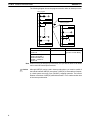
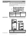
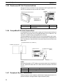
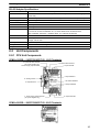
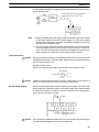
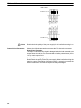
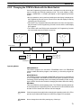
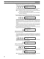
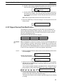
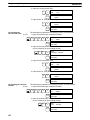
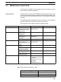
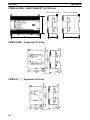
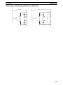
Wiring and Connections Section 3-4 COM 01 00 ! Caution 54 Load 07 Load 06 05 Load Load Load 03 02 04 COM 24 VDC+10%/–15% Load Load 24 VDC+10%/–15% Load CPM1A-8ET Double-check the polarity of the power supply for the load before turning it on. Wiring and Connections Section 3-4 Transistor Output Wiring (Source Type) Wire the outputs to the CPM1A’s CPU Unit and Expansion I/O Unit as shown in the following diagrams. • Always use solid wire or attach crimp connectors if a stranded wire is used. • Don’t exceed the output capacity or the maximum common current. Refer to 2-1-3 I/O Specifications for details. Item Specification Output capacity 300 mA (24 VDC) Max. common capacity 0.9 A/common Output Configurations 10 CH Load 24 VDC+10%/–15% 02 COM 03 Load COM Load 01 COM Load 00 CPM1A-10CDT1-D Common CPM1A-20CDT1-D/CPM1A-20EDT1 10 CH 04 05 Common CPM1A-30CDT1-D 07 COM 06 Load Load 03 Load Load Load Common 11 CH CPM1A-40CDT1-D COM 06 Common Load Load Common Common 03 Common Common 04 Common Load Load 03 05 COM 07 06 Load Load 02 01 Load 00 COM Load 07 06 Load 05 COM Load Load 04 03 Load 02 COM Load Load Load Load 01 COM Load 00 24 VDC+10%/–15% 02 01 11 CH Load 10 CH COM 00 COM Load 07 Load 03 05 Load 04 Load COM Load Load 24 VDC+10%/–15% COM 02 Load COM 01 Load 00 Load 10 CH Load 24 VDC+10%/–15% 02 COM Load 01 COM Load Load 00 COM Common 55 Wiring and Connections Section 3-4 COM 01 00 ! Caution Output Wiring Precautions Load 07 Load 06 05 Load Load Load 03 02 04 COM 24 VDC+10%/–15% Load 24 VDC+10%/–15% Load Load CPM1A-8ET1 Double-check the polarity of the power supply for the load before turning it on. Observe the following precautions to protect the PC’s internal components. Output Short Protection The output or internal circuitry might be damaged when the load connected to an output is short-circuited, so it is recommended to install a protective fuse (0.5 to 1.0 A) in each output circuit. Polarity of Power Supply for the Load Double-check the polarity of the DC power supply for the load before wiring the transistor output. If the polarity of the power supply is reversely connected, the load will malfunction and internal components may be damaged. 56 Wiring and Connections Section 3-4 Inductive Loads When connecting an inductive load to an input, connect a surge protector or diode in parallel with the load. The surge protector’s components should have the following ratings: Relay Output OUT CPM1A Surge protector COM Relay Output Transistor Output (Sink Type) OUT CPM1A Diode COM Relay Output Transistor Output (Source Type) OUT CPM1A Diode COM The diode should satisfy the following requirements: Peak reverse-breakdown voltage must be at least 3 times the load voltage. Average rectified current must be 1 A. Inrush Current Considerations When switching a load with a high inrush current in the CPM1A relay output or transistor output model, such as an incandescent lamp, suppress the inrush current as shown below. Countermeasure 1 Countermeasure 2 R OUT OUT R COM COM Providing a dark current of approx. one-third of the rated value through an incandescent lamp Providing a limiting resistor Fuse Insertion The CPM1A with transistor output may burn if the load is short-circuited, therefore, insert a protective fuse in series to the load. Crimp Connectors ! Caution Always use crimp connectors for the CPM1A’s power lines and I/O lines or else use a solid wire (instead of a stranded wire). Do not connect bare stranded wires directly to terminals. Bare stranded wires connected directly to the terminal can cause a fire. Use M3 terminal screws and tighten the screws securely (0.5 N m). Fork terminal 6.2 mm max. Ring terminal 6.2 mm max. The recommended wire size for solid wires is 0.4 to 1.2 mm (AWG26 to AWG18). 57 Wiring and Connections Section 3-4 3-4-6 Peripheral Device Connection The CPM1A CPU Unit can be connected to a C200H-PRO27-E Programming Console with a standard C200H-CN222 (2 m) or C200H-CN422 (4 m) Connecting Cable. The CPM1A CPU Unit can be also connected to a CQM1-PRO01-E. The CQM1-PRO01-E is provided with a 2-m Connecting Cable. 3-4-7 Host Link Connections Host Link is a command/response communications system in which commands are transmitted from the host computer and corresponding responses are returned from the destination PCs. Host Link commands can be used to read/ write data in PC data areas and read/write PC settings. One-to-one Host Link Connection The CPM1A CPU Unit can be connected to an IBM PC/AT compatible computer or a Programmable Terminal with an RS-232C Adapter, as shown in the following diagram. RS-232C Adapter 58 CPM1A CPU Unit Command Command OMRON PT RS-232C Adapter CPM1A CPU Unit Wiring and Connections Section 3-4 The following diagram shows the wiring in the RS-232C cable used to connect a CPM1A to a host computer or Programmable Terminal. IBM PC/AT compatible computer or Programmable Terminal (9-pin) RS-232C Adapter Signal Pin No. Pin No. Signal CD 1 1/Cover FG RD 2 2 SD SD 3 3 RD ER 4 4 RS SG 5 5 CS DR 6 6 – RS 7 7 – CS 8 8 – CI 9 9 SG The type of connector used will vary depending on the PT. Check the PT manual to ensure the correct connector is used. Note When the CPM1A is connected to a host computer or OMRON PT, set the RS-232C Adapter’s mode setting switch to “HOST.” One-to-N Host Link Connection Up to 32 CPU Units can be connected to an IBM PC/AT compatible computer or a Programmable Terminal with a 3G2A9-AL004-E Link Adapter and RS-422 Adapters, as shown in the following diagram. RS-232C cable Link Adapter 3G2A9-AL004-E RS-422 cable RS-422 Adapter CPM1A CPU Unit RS-422 Adapter CPM1A CPU Unit RS-422 Adapter CPM1A CPU Unit 59 Wiring and Connections Section 3-4 The following diagram shows the wiring in the RS-422 cables used to connect CPM1A PCs to a 3G2A9-AL004-E Link Adapter. In both the Link Adapter/ RS-422 Adapter connections and the RS-422 Adapter/RS-422 Adapter connections, connect the SG, RDA, RDB, SDA, and SDB terminals to the same terminals in the other Adapter. 3G2A9-AL004-E Link Adapter 9-pin D-sub Connector Pin no. Signal 25-pin D-sub Connector Use a straight RS-232C cable to connect to the host computer’s RS-232C port. RDB – SG – SDB RDA FG – SDA 1 2 3 4 5 6 7 8 9 RS-422 Adapter CPM1A CPU Unit SG RDA RDB SDA SDB Note 1. The maximum length of the RS-422 cable should be 500 m. 2. Set the termination resistance switch to “ON” (upper side) for Adapters on both ends of the Host Link system. Always use crimp connectors when wiring the RS-422 Adapters. Use M3 terminal screws and tighten the screws securely to the torque of 0.5 N m. Fork terminal 6.2 mm max. 60 Ring terminal 6.2 mm max. Wiring and Connections Section 3-4 3-4-8 One-to-one PC Link Connections A CPM1A can be linked to a CPM1A, CQM1, CPM1, CPM2A, CPM2C, SRM1(-V2) or a C200HS or C200HX/HE/HG PC through an RS-232C Adapter. One PC acts as the Master and the other as the Slave to link up to 256 bits in the LR area (LR 0000 to LR 1515). RS-232C Cable RS-232C Adapter (see note) RS-232C Adapter (see note) CPM1A CPU Unit Link bits Link bits LR 00 WRITE LR 00 WRITE area READ READ area LR 07 LR 08 LR 07 LR 08 READ area READ CPM1A CPU Unit WRITE area LR 15 WRITE LR 15 Note One-to-one PC connections can only be used when the RS-232C Adapter (CPM1-CIF01) is connected. Set the DIP switch of the RS-232C Adapter (CPM1-CIF01) to the NT (bottom) side. The following diagram shows the wiring in the RS-232C cable used to connect a CPM1A to another PC. RS-232C Adapter Signal FG RS-232C Adapter Pin No. Pin No. Signal 1/Cover 1/Cover FG SD 2 2 SD RD 3 3 RD RS 4 4 RS CS 5 5 CS – 6 6 – – 7 7 – – 8 8 – SG 9 9 SG 61 Wiring and Connections Section 3-4 3-4-9 One-to-one NT Link Connections High-speed communications can be achieved by providing a direct access through the use of the 1:1 NT Link between the CPM1A and Programmable Terminal. OMRON Programmable Terminal CPM1A CPU Unit RS-232C Cable RS-232C Adapter Note The 1:1 NT Link can only be used when the RS-232C Adapter (CPM1-CIF01) is connected. Set the DIP switch of the RS-232C Adapter (CPM1-CIF01) to the NT (bottom) side. The following diagram shows the wiring in the RS-232C cable used to connect a CPM1A to a Programmable Terminal. RS-232C Adapter PT 62 Signal Pin No. Pin No. Signal – 1 1/Cover FG SD 2 2 SD RD 3 3 RD RS 4 4 RS CS 5 5 CS – 6 6 – – 7 7 – – 8 8 – SG 9 9 SG Wiring and Connections Section 3-4 3-4-10 CompoBus/S I/O Link Connections A CompoBus/S I/O Link can be used to create an I/O link (remote I/O) of 8 input points and 8 output points with a CompoBus/S Master Unit or SRM1 PC. The connection is made through a CompoBus/S I/O Link Unit. From the standpoint of the CPM1A CPU Unit, the area allocated to the CompoBus/S I/O Link Unit can be treated just like the area allocated to an Expansion I/O Unit. The difference is that the bits are not actual I/O points, but I/O bits in the Master Unit. CompoBus/S Master Unit (or SRM1 PC) CPM1A CPU Unit C200HX/HG/HE PC CompoBus/S I/O Link Unit (Slave) Cables Use special flat cable or VCTF cable to connect the nodes in the CompoBus/S I/O Link. (Special flat cables and VCTF cables cannot be combined in the same system.) Name Specifications Flat cable 4-core flat cable, 0.75 mm2 VCTF cable 2-core x 0.75 mm2 63 SECTION 4 Using Peripheral Devices This section outlines the operations possible with the SYSMAC Support Software (SSS) and the Programming Consoles. Actual SSS operating procedures are provided in the SSS Operation Manuals: Basics and C-series PCs. Programming Console connection and operating procedures are provided in this section. 4-1 4-2 4-3 4-4 Support Software Capabilities . . . . . . . . . . . . . . . . . . . . . . . . . . . . . . . . . . . . . . . . . . . . . . . 4-1-1 SSS System Setup . . . . . . . . . . . . . . . . . . . . . . . . . . . . . . . . . . . . . . . . . . . . . . . . . 4-1-2 CPM1A Restrictions and Precautions . . . . . . . . . . . . . . . . . . . . . . . . . . . . . . . . . . 4-1-3 Offline Operations . . . . . . . . . . . . . . . . . . . . . . . . . . . . . . . . . . . . . . . . . . . . . . . . . 4-1-4 Online Operations . . . . . . . . . . . . . . . . . . . . . . . . . . . . . . . . . . . . . . . . . . . . . . . . . 4-1-5 Offline and Online Operations . . . . . . . . . . . . . . . . . . . . . . . . . . . . . . . . . . . . . . . . Using a Programming Console . . . . . . . . . . . . . . . . . . . . . . . . . . . . . . . . . . . . . . . . . . . . . . 4-2-1 Compatible Programming Consoles . . . . . . . . . . . . . . . . . . . . . . . . . . . . . . . . . . . 4-2-2 Changing the CPM1A’s Mode with the Mode Switch . . . . . . . . . . . . . . . . . . . . . . 4-2-3 Connecting the Programming Console . . . . . . . . . . . . . . . . . . . . . . . . . . . . . . . . . 4-2-4 Preparation for Operation . . . . . . . . . . . . . . . . . . . . . . . . . . . . . . . . . . . . . . . . . . . 4-2-5 Entering the Password . . . . . . . . . . . . . . . . . . . . . . . . . . . . . . . . . . . . . . . . . . . . . . Programming Console Operations . . . . . . . . . . . . . . . . . . . . . . . . . . . . . . . . . . . . . . . . . . . . 4-3-1 Overview . . . . . . . . . . . . . . . . . . . . . . . . . . . . . . . . . . . . . . . . . . . . . . . . . . . . . . . . 4-3-2 Clearing Memory . . . . . . . . . . . . . . . . . . . . . . . . . . . . . . . . . . . . . . . . . . . . . . . . . . 4-3-3 Reading/Clearing Error Messages . . . . . . . . . . . . . . . . . . . . . . . . . . . . . . . . . . . . . 4-3-4 Buzzer Operation . . . . . . . . . . . . . . . . . . . . . . . . . . . . . . . . . . . . . . . . . . . . . . . . . . 4-3-5 Setting and Reading a Program Memory Address and Monitoring I/O Bit Status 4-3-6 Entering or Editing Programs . . . . . . . . . . . . . . . . . . . . . . . . . . . . . . . . . . . . . . . . 4-3-7 Instruction Search . . . . . . . . . . . . . . . . . . . . . . . . . . . . . . . . . . . . . . . . . . . . . . . . . 4-3-8 Bit Operand Search . . . . . . . . . . . . . . . . . . . . . . . . . . . . . . . . . . . . . . . . . . . . . . . . 4-3-9 Inserting and Deleting Instructions . . . . . . . . . . . . . . . . . . . . . . . . . . . . . . . . . . . . 4-3-10 Checking the Program . . . . . . . . . . . . . . . . . . . . . . . . . . . . . . . . . . . . . . . . . . . . . . 4-3-11 Bit, Digit, Word Monitor . . . . . . . . . . . . . . . . . . . . . . . . . . . . . . . . . . . . . . . . . . . . 4-3-12 Differentiation Monitor . . . . . . . . . . . . . . . . . . . . . . . . . . . . . . . . . . . . . . . . . . . . . 4-3-13 Binary Monitor . . . . . . . . . . . . . . . . . . . . . . . . . . . . . . . . . . . . . . . . . . . . . . . . . . . 4-3-14 Three-word Monitor . . . . . . . . . . . . . . . . . . . . . . . . . . . . . . . . . . . . . . . . . . . . . . . 4-3-15 Signed Decimal Monitor . . . . . . . . . . . . . . . . . . . . . . . . . . . . . . . . . . . . . . . . . . . . 4-3-16 Unsigned Decimal Monitor . . . . . . . . . . . . . . . . . . . . . . . . . . . . . . . . . . . . . . . . . . 4-3-17 Three-word Data Modification . . . . . . . . . . . . . . . . . . . . . . . . . . . . . . . . . . . . . . . 4-3-18 Changing Timer, Counter SV . . . . . . . . . . . . . . . . . . . . . . . . . . . . . . . . . . . . . . . . 4-3-19 Hexadecimal, BCD Data Modification . . . . . . . . . . . . . . . . . . . . . . . . . . . . . . . . . 4-3-20 Binary Data Modification . . . . . . . . . . . . . . . . . . . . . . . . . . . . . . . . . . . . . . . . . . . 4-3-21 Signed Decimal Data Modification . . . . . . . . . . . . . . . . . . . . . . . . . . . . . . . . . . . . 4-3-22 Unsigned Decimal Data Modification . . . . . . . . . . . . . . . . . . . . . . . . . . . . . . . . . . 4-3-23 Force Set, Reset . . . . . . . . . . . . . . . . . . . . . . . . . . . . . . . . . . . . . . . . . . . . . . . . . . . 4-3-24 Clear Force Set/Reset . . . . . . . . . . . . . . . . . . . . . . . . . . . . . . . . . . . . . . . . . . . . . . . 4-3-25 Hex-ASCII Display Change . . . . . . . . . . . . . . . . . . . . . . . . . . . . . . . . . . . . . . . . . 4-3-26 Displaying the Cycle Time . . . . . . . . . . . . . . . . . . . . . . . . . . . . . . . . . . . . . . . . . . Programming Example . . . . . . . . . . . . . . . . . . . . . . . . . . . . . . . . . . . . . . . . . . . . . . . . . . . . . 4-4-1 Preparatory Operations . . . . . . . . . . . . . . . . . . . . . . . . . . . . . . . . . . . . . . . . . . . . . 4-4-2 Example Program . . . . . . . . . . . . . . . . . . . . . . . . . . . . . . . . . . . . . . . . . . . . . . . . . 4-4-3 Programming Procedures . . . . . . . . . . . . . . . . . . . . . . . . . . . . . . . . . . . . . . . . . . . . 4-4-4 Checking the Program . . . . . . . . . . . . . . . . . . . . . . . . . . . . . . . . . . . . . . . . . . . . . . 4-4-5 Test Run in MONITOR Mode . . . . . . . . . . . . . . . . . . . . . . . . . . . . . . . . . . . . . . . . 66 66 66 67 69 70 71 71 73 74 75 75 77 77 78 79 79 80 81 84 84 85 86 87 89 89 90 91 91 92 92 93 94 95 96 96 97 97 98 98 98 100 101 104 104 65 Section 4-1 Support Software Capabilities 4-1 Support Software Capabilities The SSS is a complete programming and control package designed for C-series and CVM1 PCs. It provides not only programming capabilities, but also advanced debugging, monitoring, and program/data management. The following tables provide only a brief introduction to the capabilities of the SSS. For further information and actual operating procedures, please refer to the SYSMAC Support Software Operation Manuals: Basics and C-series. CPM1A programming can be performed with any version of the SSS. In addition, the SYSMAC-CPT can be used for programming the CPM1A. Refer to the SYSMAC-CPT Support Software Quick Start Guide (W332) and User Manual (W333) for operation procedures. When programming the CPM1A using the SYSMAC-CPT, be sure to set the “PC model” on the Support Software to “CPM1 (CPM1A).” 4-1-1 SSS System Setup Set the PC Model to “CQM1” and the PC Interface to “PERIPHERAL.” Follow the directions in the SSS operating manuals for other System Setup settings. PC Model If the CPM1A PC doesn’t appear as an option in the SSS’s System Setup, set the PC Model to “CQM1.” The CPM1A is compatible with the CQM1. PC Interface Set the PC Interface to the Peripheral Device Port by selecting “PERIPHERAL” from the submenu. After selecting the Peripheral Device Port, set the communications baud rate to 9,600 baud. 4-1-2 CPM1A Restrictions and Precautions When programming the CPM1A, set the PC Model on the SSS to “CQM1.” Heed the following restrictions when programming the CPM1A. Programming Check Since the data area of the CQM1 is larger than that of the CPM1A, some parts of the area cannot be checked as the CPM1A PC. Pay careful attention to the usable data area when programming. Note If a program that contains addresses not supported by the CPM1A are transferred to the CPM1A, a memory error will occur when operation is begun and AR 1308 will turn ON. Refer to the Programming Manual (W353) for differences in memory areas. Memory Usage Since the memory of the the CQM1 is larger than that of the CPM1A, the displayed available memory capacity is larger than the actual available memory capacity. Pay careful attention to the actual available memory capacity when programming. Expansion Instructions When a program is transferred after changing the assignment of function codes for the 18 expansion instructions, a message to “Turn on the DIP switch of the PC and execute again” is displayed. Change the assignment of the function codes for the expansion instructions to the default settings before programming. The default settings for the CQM1 are as shown in the following table. Function code 66 Mnemonic Function code Mnemonic 17 ASFT 64 SPED 18 TKY 65 PULS 19 MCMP 66 SCL 47 RXD 67 BCNT 48 TXD 68 BCMP 60 CMPL 69 STIM 61 INI 87 DSW 62 PRV 88 7SEG 63 CTBL 89 INT Section 4-1 Support Software Capabilities Online Editing If unsupported addresses are set in the program for operands or set values, error messages will be displayed and the values will not be accepted. 4-1-3 Offline Operations The following operations are possible when not connected online to the PC. Group Programming Name Description Connect line Draws a line between two ladder diagram objects. Save program Writes all or part of the user program developed in the system work area to the data disk. Retrieves all or part of the user program stored on a data disk to the system work area. Specifies the display modes for the user program. Retrieve program Change display Search I/O comment Instr comment Block comment Edit ladder Searches for instructions including specified operands. An address from which the search is to be started can be specified Creates I/O comments corresponding to bit addresses in the Ladder With Comments mode. In addition, reads (searches) and edits the program for comments. Creates and edits instruction comments for output instructions in the Ladder With Comments mode. (C-series PCs only) Creates, reads (searches), and edits block comment in the Ladder With Comments mode. Edits ladder diagrams using the following: • Moving specified instruction blocks • Copying specified instruction blocks • Deleting specified instruction blocks Edit comments Retrieve comments Memory usage Clear memory Check program DM (data memory) Go To Page Copy Fill Print I/O Table Displays I/O comments simultaneously to write, edit, and search for specified comments. Retrieves comments from the program stored on a data disk. The I/O comments are read to the system work area. Instruction comments (C-series PCs only) and block comments are copied to the currently displayed program. Displays the used capacity of the user program memory, the number of comments used, and the available capacity of the internal memory. Clears the user program memory. The starting address for clearing can be specified. The comment memory can also be cleared. Checks whether the user program contains syntax errors. The check can be performed in three levels. Displays the contents of the data memory in the system work area in pages (units of 160 words). The data can be altered with this function. (C-series PCs only) Copies the contents of the DM area of the system work area (data memory information). Writes the same data to more than one data word in the system work area data memory area. Prints a specified range of DM words. Hex <—> ASCII Specifies the display mode for the data memory contents when the work disk data memory contents are to be altered. The display mode can be hexadecimal or ASCII. Save DM Data Retrieve DM Data Writes the contents of a specified range of system work area data memory to the data disk. Retrieves the saved data disk data memory to the system work area DM area. Write I/O Table Edits the I/O table in the system work area. Check I/O Table Checks the contents of the I/O table in the system work area. Save I/O Table Writes the I/O table in the system work area to a data disk. Retrieve I/O Table Retrieves the I/O table data stored on a data disk to the system work area. Print I/O Table Prints an I/O table list. (C-series PCs only) 67 Section 4-1 Support Software Capabilities Group Utility Name Data Area Lists Change Addresses Print Lists EPROM/Memory Card Program Conversion Description Displays lists (such as used areas and cross-references) in accordance with the contents of the user program in the system work area. Globally changes bit and word addresses in the user program in the system work area. Prints lists, ladder diagrams, and mnemonics in accordance with the contents of the user program in the system work area. Writes, reads, and compares the user program between the PROM Writer/Memory Card and system work area. C500 → C2000H: Converts C500-family programs to C2000H programs. C2000H → CVM1: Converts C2000H-family programs to CVM1 programs Create Library File Time Chart Monitor Instruction Trace Data trace Set Instructions Creates a library on a floppy disk or hard disk for use as an LSS data disk. Retrieve/Save Instr PC Setup Network Support Table Directory Used to save and retrieve expansion instruction sets to and from data disk files. (C-series PCs only) Used to set the PC operating parameters in the PC Setup and to save and retrieve PC Setups to and from data disk files. Used to allocate parts of the user memory area for used as a Fixed DM Area and/or I/O Comment Area. (C-series PCs only) Used to edit data link tables and routing tables for the SYSMAC NET and SYSMAC LINK Systems. Displays a file list. Wildcard names can be used to display only desired files. Copy File Copies files on the same floppy disk or between different disks. Allocate UM File Management Accesses the time chart monitor data produced online. (C-series PCs only) Accesses the instruction trace data produced online. (C-series PCs only) Accesses the data trace data produced online. Used to assign instructions to function codes in the instructions table and to save and retrieve instructions tables to and from data disk files. (C-series PCs only) Change File Name Changes the name of a specified file. Delete File Deletes a specified file. LSS File Used to change between LSS-style data files and DOS-style data files. Management 68 Section 4-1 Support Software Capabilities 4-1-4 Online Operations The following operations are possible when connected online to the PC. Group Monitoring Name Monitor Data Transfer Program Change Display Description Uses the lower one third of the screen as a monitor area where bits, words, DM contents, and TIM/CNT SV/PV are monitored, forced-set/reset, and changed. Transfers and compares the user program between the computer and PC. C-series PCs Ladder W/Comments Ladder CVM1 PCs Ladder Ladder (2 rows of comments) Ladder (4 rows of comments) DM I/O Table Online Edit Simultaneously edits the PC program and the program in the system work area. Read Cycle Time Reads and displays the scan time of the PC. Clear Area Clears the PC data areas such as HR, CNT, AR, and DM (to zero). Search Searches for instructions (including specified operands). I/O Comments Searches for I/O comments. Block Comments Searches for block comments. Memory Usage Displays used program memory area, the number of comments used, and the available capacity of the internal memory. Retrieves PC DM data to the system work area. (C-series PCs only) Transfer PC —> Computer Transfer Computer—>PC Transfer Verify Monitor Go To Page Transfer I/O Table Create I/O Table Verify I/O Table Utility File Memory/ Memory Card Time Chart Monitor Instruction Trace Data Trace Debug Display/Set Clock Transfer Instr PC Setup Network Support Tables Writes system work area DM data to the PC. (C-series PCs only) Compares DM data between the system work area and PC. (C-series PCs only) Used to monitor DM area contents in the PC. (C-series PCs only) Reads a specified page from the DM list of the DM area in the system work area or PC. (C-series PCs only) Transfers and compares the I/O table data between the computer and PC. Registers into the PC the I/O Units mounted on the PC and then assigns the words to the Units. Compares the I/O table registered in the PC against the I/O Units actually mounted on the PC. Displays a file memory list; transfers the file memory contents between the PC and computer or the PC and File Memory Unit; clears the file memory; saves or retrieves the file memory contents to or from a floppy disk; and edits file memory contents Used to execute time chart monitoring and to display, save, or retrieve results. (C-series PCs only) Used to execute instruction traces and used to display, save, or retrieve results. (C-series PCs only) Used to execute data traces and used to display, save, or retrieve results. Used to display the execution status of the specified program section. (C-series PCs only) Used to read and set the internal clock in the PC. (CQM1, C200HS, or CVM1 only) Used to transfer expansion instruction set from the PC to the SSS. (C-series PCs only) Changes the PC Setup in the PC and in the system work area and used to transfer the PC Setup between the PC the disk (save/retrieve). C-series PCs: Used to input data link tables for SYSMAC NET. CVM1 PCs: Used to transfer data link tables and routing tables between Link Units, the PC, and the SSS and to compare these tables. Also used to start and start data links. 69 Section 4-1 Support Software Capabilities 4-1-5 Offline and Online Operations The following operations are possible either online or offline from the PC. Group System Setup (see note) Name PC model PC Interface Description Specifies the model of PC that is being programmed or that is connected to the computer. C-series PCs: Specifies whether communications with the PC are performed through a SYSMAC NET Link Unit, peripheral interface, or a Host Link (RS-232C) interface and the computer port (COM1 or COM2) to use. When a Host Link Unit is used, it also specifies the port number and baud rate. CVM1 PCs: Network address Used to specify the communications protocol for communications with the PC, i.e., peripheral or Host Link (RS-232C) interface. The baud rate, PC unit number, parity, data length, and number of stop bits are designated. Specifies the network address, node number, and data code type of the SYSMAC NET Link Unit communicating with the SSS on the SYSMAC NET System. The address determines the PC to be connected to for online operations. I/O table – UM transfer With CVM1 PCs this setting is also used to specify the PC being communicated with through networks when connected via a peripheral or Host Link interface. Specifies whether the I/O table and data link tables are transferred to the user program area when the user program is transferred between the computer and PC or PROM Writer. (C-series PCs only) EPROM interface Printer model Specifies the baud rate and port number of the PROM Writer connected to the computer. (C-series PCs only) Specifies the printer model. Data disk drive Specifies the data disk drive. OutBit Comment Type Specifies whether I/O comments or instruction comments are displayed at the TIM/CNT, DIFU/DIFD, KEEP, and STEP/SNXT comment display positions. (C-series PCs only) Exit to DOS Terminates SSS operation and returns to DOS. Note When the SSS is operating in online mode, the only functions available on the System Setup Menu are “I/O table – UM transfer,” “Data disk drive,” and “Exit to DOS.” 70 Using a Programming Console 4-2 Section 4-2 Using a Programming Console This section provides information on connecting and using a Programming Console. Refer to 5-4 Programming Console Operation Errors for details on errors that might occur during Programming Console operations. 4-2-1 Compatible Programming Consoles There are two Programming Consoles that can be used with the CPM1A: The CQM1-PRO01-E and the C200H-PRO27-E. The key functions for these Programming Consoles are identical. Press and release the Shift Key to input a letter shown in the upper-left corner of the key or the upper function of a key that has two functions. For example, the CQM1-PRO01-E’s AR/HR Key can specify either the AR or HR Area; press and release the Shift Key and then press the AR/HR Key to specify the AR Area. CQM1-PRO01-E LCD display Attached Connecting Cable (2 m) Mode switch Operation keys C200H-PRO27-E LCD display Mode switch Operation keys Cassette recorded jack (Cannot be used with the CPM1A). Connecting Cables C200H-CN222 (2 m) C200H-CN422 (4 m) 71 Using a Programming Console Different Keys Section 4-2 The following keys are labeled differently on the CQM1-PRO01-E and the C200H-PRO27-E, but the operation of the keys in each pair is identical. CQM1-PRO01-E Keys C200H-PRO27-E Keys AR HR HR PLAY SET SET REC RESET RESET Note To specify the AR area, use SHIFT and HR Keys for the C200H-PRO27-E and use SHIFT and AR/HR Keys for the CQM1-PRO01-E. A shift symbol will be displayed in the upper-right corner of the screen when the Shift Key is pressed. The shift input can be cleared by pressing the Shift Key again. Shift input symbol ^ SHIFT Mode Switch The mode switch controls the CPM1A’s operating mode. The key can be removed when the switch is set to RUN or MONITOR but it cannot be removed when the switch is set to PROGRAM. Contrast Control The display contrast can be adjusted with the control on the right side of the Programming Console. Contrast control Buzzer Volume The C200H-PRO27-E’s buzzer volume can be adjusted with the lever on the right side of the Programming Console. The CQM1-PRO01-E’s buzzer volume cannot be adjusted. Low volume High volume C200H-PRO27-E Note The buzzer volume can be turned on and off with a key operation. See 4-3-4 Buzzer Operation for details. 72 Using a Programming Console Section 4-2 4-2-2 Changing the CPM1A’s Mode with the Mode Switch Once the Programming Console has been connected, its mode switch can be used to change the CPM1A’s operating mode. The mode display (<PROGRAM>, <MONITOR>, or <RUN>) will appear on the Programming Console screen. • No key operations can be performed while the mode display is displayed on the Programming Console screen. Press CLR to clear the display so that key operations can be performed. • If the SHIFT Key is pressed while the mode switch is turned, the original display will remain on the Programming Console’s screen and the mode display won’t appear. • The CPM1A will enter RUN mode automatically if a Programming Console isn’t connected when the CPM1A is turned on. MONITOR RUN PROGRAM MONITOR RUN PROGRAM MONITOR RUN PROGRAM Mode display <PROGRAM> BZ <MONITOR> Operation CLR Initial display BZ <RUN> Operation SHIFT BZ CLR 00000 Operating Modes PROGRAM Mode The CPM1A program isn’t executed in PROGRAM mode. Use PROGRAM mode to create and edit the program, clear memory, or check the program for errors. MONITOR Mode The CPM1A program is executed in MONITOR mode and I/O is refreshed just as it is in RUN mode. Use MONITOR mode to test system operations, such as monitoring CPM1A operating status, force-setting and resetting I/O bits, changing the SV/PV of timers and counters, changing word data, and online editing. RUN Mode This is the CPM1A’s normal operating mode. The CPM1A’s operating status can be monitored from a Programming Device, but bits can’t be force-set/force-reset and the SV/PV of timers and counters can’t be changed. ! Caution Check the system thoroughly before changing the operating mode of the PC to prevent any accidents that might occur when the program is first started. ! Caution Never change the mode while pressing any of the keys. 73 Using a Programming Console Startup Operating Mode Section 4-2 The operating mode of the CPM1A when the power is turned ON depends upon the PC Setup setting in DM 6600 and the Programming Console’s mode switch setting if the Programming Console is connected. PC Setup setting (DM 6600) 0000 0200 Programming Console not connected RUN mode if no Programming Device is connected. PROGRAM mode if another Programming Device is connected. The startup mode is the same as the operating mode before power was interrupted. PROGRAM mode 0201 MONITOR mode 0202 RUN mode 0100 Programming Console connected The startup mode determined by the mode switch setting. Note The default setting is 0000. If a Programming Console is not connected, the PC will automatically enter RUN mode. Be sure that it is safe for the PC to operate before turning on the PC without a Programming Console connected. 4-2-3 Connecting the Programming Console Connect the Programming Console’s connecting cable to the CPM1A’s peripheral port, as shown below. Panel Installation The C200H-PRO27-E Programming Console can be installed in a control panel as shown in the following diagram. (The C200H-ATT01 Mounting Bracket is sold separately.) Mounting Bracket Mounting hole dimensions (DIN43700 standards) Two screws +1.1 186 –0 Panel thickness: 1.0 to 3.2 mm 74 92 +0.8 –0 Using a Programming Console Section 4-2 Allow at least 80 mm for the cable connector above the Programming Console. 37 15 At least 80 mm is required. Either connector may be used. About 70 mm is required. 4-2-4 Preparation for Operation This section describes the procedures required to begin Programming Console operation when using the Programming Console for the first time. ! Caution Always confirm that the Programming Console is in PROGRAM mode when turning ON the PC with a Programming Console connected unless another mode is desired for a specific purpose. If the Programming Console is in RUN mode when PC power is turned ON, any program in Program Memory will be executed, possibly causing a PC-controlled system to begin operation. The following sequence of operations must be performed before beginning initial program input. 1, 2, 3... 1. Be sure that the PC is OFF. 2. Connect the Programming Console to the CPU Unit’s peripheral port. See 4-2-3 Connecting the Programming Console for details. (The CPU Unit’s Communications Switch setting has no effect on communications with the Programming Console.) 3. Set the mode switch to PROGRAM mode. 4. Turn ON the PC. 5. Enter the password. See 4-2-5 Entering the Password for details. 6. Clear (All Clear) the PC’s memory. See 4-3-2 Clearing Memory for details. 7. Read and clear all errors and messages. See 4-3-3 Reading/Clearing Error Messages for details. 8. Start programming. 4-2-5 Entering the Password To gain access to the PC’s programming functions, you must first enter the password. The password prevents unauthorized access to the program. The PC prompts you for a password when PC power is turned on or, if PC power is already on, after the Programming Console has been connected to the PC. To gain access to the system when the “Password!” message appears, press CLR and then MONTR. Then press CLR to clear the display. 75 Using a Programming Console Section 4-2 If the Programming Console is connected to the PC when PC power is already on, the first display below will indicate the mode the PC was in before the Programming Console was connected. Ensure that the PC is in PROGRAM mode before you enter the password. When the password is entered, the PC will shift to the mode set on the mode switch, causing PC operation to begin if the mode is set to RUN or MONITOR. The mode can be changed to RUN or MONITOR with the mode switch after entering the password. <PROGRAM> PASSWORD! <PROGRAM> BZ Indicates the mode set by the mode selector switch. 76 Programming Console Operations 4-3 Section 4-3 Programming Console Operations 4-3-1 Overview The following table lists the programming and monitoring operations that can be performed from a Programming Console. Refer to the rest of this section for details on operational procedures. Name Clearing memory Function Page 78 Setting a program memory address Reading a program memory address/monitoring bit status Instruction search Clears all or part of the Program Memory and any data areas that are not read-only, as well as the contents of the Programming Console’s memory. Displays and clears error messages and displays MESSAGE instruction messages. Turns ON and OFF the buzzer that sounds when Programming Console keys are pressed. Sets the specified program memory address when reading, writing, inserting and deleting programs. Reads the contents of the Program Memory. Displays the status of the currently displayed bit in PROGRAM and MONITOR modes. Finds occurrences of the specified instruction in the program. Bit operand search Finds occurrences of the specified operand bit in the program. 84 Inserting and deleting instructions Entering or editing programs Inserts or deletes instructions from the program. 85 81 Multiple address monitor Overwrites the contents of the current Program Memory to either input a program for the first time or to change a program that already exists. Checks for programming errors and displays the program address and error when errors are found. Monitors the status of up to 16 bits and words, although only 3 can be shown on the display at one time. Monitors the status of up to 6 bits and words simultaneously. Differentiation monitor Monitors ON-to-OFF or OFF-to-ON changes in the status of a particular bit. 89 Binary monitor Monitors the ON/OFF status of any word’s 16 bits. 89 Three-word monitor Monitors the status of three consecutive words. 90 Signed decimal monitor Converts the contents of the specified word from signed hexadecimal (two’s complement format) to signed decimal for display. Converts hexadecimal data in a word to unsigned decimal for display. 91 92 Changing timer, counter SV 1 Changes the contents of one or more of the 3 consecutive words displayed in the Three-word Monitor operation. Changes the SV of a timer or counter. Changing timer, counter SV 2 Makes fine adjustment changes to the SV of the timer or counter. 93 Hexadecimal, BCD data modification Binary data modification Changes the BCD or hexadecimal value of a word being monitored. 93 Changes the status of a word’s bits when the word is being monitored. 94 Signed decimal data modification Changes the decimal value of a word being monitored as signed decimal data 95 within a range of –32,768 to 32,767. The contents of the specified word are converted automatically to signed hexadecimal (two’s complement format.) Unsigned decimal data modification Changes the decimal value of a word being monitored as unsigned decimal data within a range of 0 to 65,535. A change to hexadecimal data is made automatically. 96 Force set/reset Forces bits ON (force set) or OFF (force reset.) 96 Clear force set/reset Restores the status of all bits which have been force set of reset. 97 Hex-ASCII display change Converts word data displays back and forth between 4-digit hexadecimal data 97 and ASCII. Displays the current average cycle time (scan time.) 98 Reading/clearing error messages Buzzer operation Checking the program Bit, digit, word monitor Unsigned decimal monitor Three-word data modification Displaying the cycle time 79 79 80 80 84 86 87 88 91 92 77 Programming Console Operations Section 4-3 4-3-2 Clearing Memory This operation is used to clear all or part of the Program Memory and data areas, as well as the contents of the Programming Console’s memory. This operation is possible in PROGRAM mode only. RUN MONITOR No No PROGRAM OK Before beginning to program for the first time or when installing a new program, clear all areas. All Clear The following procedure is used to clear memory completely, including the program, all data areas, counter PVs, Data Memory, and the PC Setup (DM 6600 to DM 6655). 1, 2, 3... 1. Bring up the initial display by pressing the CLR Key repeatedly. 2. Press the SET, NOT, and then the RESET Key to begin the operation. SET NOT RESET 00000MEMORY CLR? HR CNT DM 3. Press the MONTR Key to clear memory completely. MONTR ! Caution Partial Clear 00000MEMORY CLR END HR CNT DM The PC Setup (DM 6600 through DM 6655) will be cleared when this operation is performed. It is possible to retain the data in specified areas or part of the Program Memory. To retain the data in the HR, TC, or DM Areas, press the appropriate key after pressing SET, NOT, and RESET. Any data area that still appears on the display will be cleared when the MONTR Key is pressed. The HR Key is used to specify both the AR and HR Areas, the CNT Key is used to specify the entire timer/counter area, and the DM Key is used to specify the DM Area. It is also possible to retain a portion of the Program Memory from the first memory address to a specified address. After designating the data areas to be retained, specify the first Program Memory address to be cleared. For example, input 030 to leave addresses 000 to 029 untouched, but to clear addresses from 030 to the end of Program Memory. As an example, follow the procedure below to retain the timer/counter area and Program Memory addresses 000 through 122: 1, 2, 3... 1. Press the CLR Key to bring up the initial display. 2. Press the SET, NOT, and then the RESET Key to begin the operation. 3. Press the CNT Key to remove the timer/counter area from the data areas shown on the display. (Counter PVs will not be cleared.) CNT 00000MEMORY CLR? HR DM 4. Press 123 to specify 123 as the starting program address. B 1 C 2 D 3 00123MEMORY CLR? HR DM 5. Press the MONTR Key to clear the specified regions of memory. MONTR 78 00000MEMORY CLR END HR DM Programming Console Operations Section 4-3 4-3-3 Reading/Clearing Error Messages This operation is used to display and clear error messages. It is possible to display and clear non-fatal errors and MESSAGE instruction messages in any mode, but fatal errors can be cleared in PROGRAM mode only. RUN MONITOR OK OK PROGRAM OK Before inputting a new program, any error messages recorded in memory should be cleared. It is assumed here that the causes of any of the errors for which error messages appear have already been taken care of. If the buzzer sounds when an attempt is made to clear an error message, eliminate the cause of the error, and then clear the error message. (Refer to Section 5 Test Runs and Error Processing for troubleshooting information.) Key Sequence Follow the procedure below to display and clear messages. 1, 2, 3... 1. Press the CLR Key to bring up the initial display. 2. Press the FUN and then the MONTR Key to begin the operation. If there are no messages, the following display will appear: FUN MONTR ERR/MSG CHK OK If there are messages, the most serious message will be displayed when the MONTR Key is pressed. Pressing MONTR again will clear the present message and display the next most serious error message. Continue pressing MONTR until all messages have been cleared. These are some examples of error messages: A memory error: MONTR MEMORY ERR A system error: MONTR SYS FAIL FAL01 A message (displayed with MSG(46)): MONTR MATERIAL USED UP All messages cleared: MONTR ERR/MSG CHK OK 4-3-4 Buzzer Operation This operation is used to turn ON and OFF the buzzer that sounds when Programming Console keys are pressed. This buzzer will also sound whenever an error occurs during PC operation. Buzzer operation for errors is not affected by this setting. This operation is possible in any mode. RUN OK MONITOR OK PROGRAM OK 79 Programming Console Operations Key Sequence Section 4-3 Follow the procedure below to turn the key-input buzzer on and off. 1, 2, 3... 1. Press the CLR, SHIFT, and then the CLR Key to bring up the mode display. In this case the PC is in PROGRAM mode and the buzzer is ON. CLR SHIFT CLR <MONITOR> BZ 2. Press the SHIFT and then the 1 Key to turn off the buzzer. SHIFT B 1 <MONITOR> The buzzer will not sound when “BZ” is not displayed. 3. Press the SHIFT and then the 1 Key again to turn the buzzer back ON. SHIFT B 1 <MONITOR> BZ 4-3-5 Setting and Reading a Program Memory Address and Monitoring I/O Bit Status This operation is used to display the specified program memory address and is possible in any mode. In the RUN or MONITOR mode, the I/O bit status of bits in the program will be displayed. RUN MONITOR OK OK PROGRAM OK When inputting a program for the first time, it is generally written to Program Memory starting from address 000. Because this address appears when the display is cleared, it is not necessary to specify it. When inputting a program starting from other than 000 or to read or modify a program that already exists in memory, the desired address must be designated. 1, 2, 3... 1. Press the CLR Key to bring up the initial display. 2. Input the desired address. It is not necessary to input leading zeroes. C 2 A 0 A 0 00200 3. Press the Down Arrow Key. ↓ 00200READ OFF LD 00000 In the RUN or MONITOR mode, ON/ OFF status of the bit will be displayed. Note The ON/OFF status of any displayed bit will be shown if the PC is in RUN or MONITOR mode. 4. Press the Up and Down Arrow Keys to scroll through the program. ↓ 00201READ ON AND 00001 ↓ 00200READ OFF LD 00000 Pressing the MONTR Key will change to the I/O monitor display. Bits can be force-set or force-reset from the I/O monitor display. Press the CLR Key to return to I/O bit status monitoring of the initial address. 80 Programming Console Operations Section 4-3 4-3-6 Entering or Editing Programs This operation is used enter or edit programs. It is possible in PROGRAM mode only. RUN MONITOR No PROGRAM No OK The same procedure is used to either input a program for the first time or to change a program that already exists. In either case, the current contents of Program Memory is overwritten. The program shown in the following diagram will be entered to demonstrate this operation. 00002 Address TIM 000 #0123 12.3 s Instruction 00200 00201 LD TIM 00202 MOV(021) Operands IR MOV(021) #0100 LR 10 LR 00203 00002 000 #0123 #0100 10 ADB(050) ADB(050) #0100 #FFF6 DM 0000 #0100 #FFF6 DM 0000 1, 2, 3... 1. Press the CLR Key to bring up the initial display. 2. Specify the address where the program will begin. 3. Input the address where the program will begin and press the Down Arrow Key. It is not necessary to input leading zeroes. C 2 A 0 A 0 ↓ 00200 4. Input the first instruction and operand. LD C 2 00200 LD 00002 5. Press the WRITE Key to write the instruction to Program Memory. The next program address will be displayed. WRITE 00201READ NOP (000) If a mistake was made inputting the instruction, press the Up Arrow Key to return to the previous program address and input the instruction again. The mistaken instruction will be overwritten To specify the Completion Flag for a timer or counter, press the LD, AND, OR, or NOT Key followed by the TIM or CNT Key, and then input the timer/ counter number last. 6. Input the second instruction and operand. (In this case it isn’t necessary to enter the timer number, because it’s 000.) Press the WRITE Key to write the instruction to Program Memory. TIM Timer number WRITE 00201 TIM DATA #0000 81 Programming Console Operations Section 4-3 7. Input the second operand (123 to specify 12.3 seconds) and press the WRITE Key. The next program address will be displayed. B C 1 2 D 3 WRITE 00202READ NOP (000) If a mistake was made inputting the operand, press the Up Arrow Key to return to display the mistaken operand and input the operand again. Note a) Counters are input in the same basic way as timers except the CNT Key is pressed instead of the TIM Key. b) Timer and counter SVs are input in BCD, so it isn’t necessary to press the CONT/# Key. 8. Input the third instruction (MOVE) and its operands. First input the instruction by pressing the FUN Key and then the function code (21 in this case). FUN C 2 B 1 00202 MOV (021) To input the differentiated version of an instruction, press the NOT Key after the function code (FUN 2 1 NOT). The “@” symbol will be displayed next to differentiated instructions. Press the NOT Key again to change back the instruction back to a non-differentiated instruction. The “@” symbol will disappear. To change an instruction after it has been entered, simply scroll through the program until the desired instruction is displayed and press the NOT Key. The “@” symbol should be displayed next to the instruction. 9. Press the WRITE Key to write the instruction to Program Memory. The input display for the first operand will be displayed. WRITE 00202 MOV DATA A 000 • Writing Hexadecimal, BCD Constant 10. Input the first operand. The operands of MOV(21) are normally word addresses, but a constant can be input by pressing the CONT/# Key first. When the CONT/# Key is pressed, the display will change to “#0000,” indicating that a constant can be entered. CONT # B 1 A 0 A 0 00202 MOV DATA A #0100 Press the WRITE Key to write the instruction to Program Memory. The input display for the second operand will appear. WRITE 00202 MOV DATA B 000 • Writing a Word Address 11. Input the second operand. *EM LR B 1 A 0 00202 MOV DATA B LR 10 Press the WRITE Key to write the instruction to Program Memory. The next program address will be displayed. WRITE 00203READ NOP (000) Note When the default display value is “000”, a word address can be input immediately without pressing the Shift and CH/# Keys. 82 Programming Console Operations Section 4-3 12. Input the next instruction (ADB). FUN F 5 A 0 00203 ADB (050) Press the WRITE Key to write the instruction to Program Memory. WRITE 00203 ADB DATA A 000 • Writing an Unsigned Decimal Number 13. The first operand is input as an unsigned integer. CONT SHIFT TR NOT 00203 ADB DATA A #00000 # Input the value of the operand from 0 to 65535. C 2 F 5 6 00203 ADB DATA A #00256 Note If an erroneous input is made, press the CLR Key to restore the status prior to the input. Then enter the correct input. 14. Restore the hexadecimal display. SHIFT TR 00203 ADB DATA A #0100 Note If an input is made outside of the permissible range, a buzzer will sound and the hexadecimal display will not be displayed. WRITE 00203 ADB DATA B 000 15. The second operand is input as a signed integer. CONT SHIFT TR # 00203 ADB DATA B #+00000 Input the value of the operand from –32,768 to 32,767. Use the SET Key to input a positive number, and use the RESET Key to input a negative number. B RESET 1 A 0 00203 ADB DATA B #-00010 Note If an erroneous input is made, press the CLR Key to restore the status prior to the input. Then enter the correct input. 16. Restore the hexadecimal display. SHIFT TR WRITE 00203 ADB DATA B #FFF6 00203 ADB DATA C 000 • Writing a Word Address (DM 0000) 17. Input the final operand and then press the WRITE Key. (It isn’t necessary to input leading zeroes.) DM WRITE 00203 ADB DATA C DM 0000 00204READ NOP (000) 83 Programming Console Operations Section 4-3 4-3-7 Instruction Search This operation is used to find occurrences of the specified instruction in the program and is possible in any mode. RUN MONITOR OK OK PROGRAM OK The ON/OFF status of any displayed bit will be shown if the PC is in RUN or MONITOR mode. 1, 2, 3... 1. Press the CLR Key to bring up the initial display. 2. Input the address from which the search will begin and press the Down Arrow Key. It is not necessary to input leading zeroes. B 1 A 0 A ↓ 0 00100READ TIM 001 3. Input the instruction to be found and press the SRCH Key. In this case, the search is for OUT 01000. In this case, the next OUT 01000 instruction is at address 200, as shown below. OUT B 1 A 0 A 0 A 0 SRCH 00200SRCH OUT 01000 4. Press the Down Arrow Key to display the instruction’s operands or press the SRCH Key to search for the next occurrence of the instruction. 5. The search will continue until an END instruction or the end of Program Memory is reached. In this case, an END instruction was reached at address 397. Indicates the address of END instruction. SRCH 00397SRCH END (001)00.4KW Indicates the amount used by the user program in units of 0.1 Kwords. 4-3-8 Bit Operand Search This operation is used to find occurrences of the specified operand bit in the program and is possible in any mode. RUN MONITOR OK OK PROGRAM OK The ON/OFF status of any displayed bit will be shown if the PC is in RUN or MONITOR mode. 1, 2, 3... 1. Press the CLR Key to bring up the initial display. 2. Input the operand address. It is not necessary to input leading zeroes. SHIFT CONT # F 5 00000CONT SRCH LD 00005 3. Press the SRCH Key to begin the search. SRCH 00123CONT SRCH LD 00005 4. Press the SRCH Key to search for the next occurrence of the operand bit. SRCH 84 00255CONT SRCH AND NOT 00005 Programming Console Operations Section 4-3 5. The search will continue until an END instruction or the end of Program Memory is reached. In this case, an END instruction was reached. Indicates the address of END instruction. SRCH 00397CONT SRCH END (001)00.4KW Indicates the amount used by the user program in units of 0.1 Kwords. 4-3-9 Inserting and Deleting Instructions This operation is used to insert or delete instructions from the program. It is possible in PROGRAM mode only. RUN MONITOR No No PROGRAM OK To demonstrate this operation, an IR 00105 NO condition will be inserted at program address 00206 and an IR 00103 NO condition deleted from address 00205, as shown in the following diagram. Original Program 00100 00101 00104 00103 Address Instruction 00205 00206 00207 00208 AND AND NOT OUT END(01) Operands 01000 00201 00102 Delete 00105 Delete Insert END(01) Insertion 00103 00104 01000 - Insert Follow the procedure below to insert the IR 00105 NO condition at address 00206. 1, 2, 3... 1. Press the CLR Key to bring up the initial display. 2. Input the address where the NO condition will be inserted and press the Down Arrow Key. It is not necessary to input leading zeroes. C 2 A 0 6 ↓ 00206READ AND NOT 00104 3. Input the new instruction and press the INS Key. AND B 1 A 0 F 5 INS 00206INSERT? AND 00105 4. Press the Down Arrow Key to insert the new instruction. ↓ 00207INSERT END AND NOT 00104 Note For instructions that require more operands (such as set values), input the operands and then press the WRITE Key. Deletion Follow the procedure below to delete the IR 00103 NO condition at address 00205. 1, 2, 3... 1. Press the CLR Key to bring up the initial display. 2. Input the address where the NO condition will be deleted and press the Down Arrow Key. It is not necessary to input leading zeroes. C 2 A 0 F 5 ↓ 00205READ AND 00103 85 Programming Console Operations Section 4-3 3. Press the DEL Key. DEL 00205DELETE? AND 00103 4. Press the Up Arrow Key to delete the specified instruction. If the instruction has more operands, the operands will be deleted automatically with the instruction. ↓ 00205 DELETE END AND 00105 After completing the insertion and deletion procedures, use the Up and Down Arrow Keys to scroll through the program and verify that it has been changed correctly, as shown in the following diagram. Corrected Program 00100 00101 00105 00104 Address Instruction 00205 00206 00207 00208 AND AND NOT OUT END(01) Operands 01000 00201 00102 END(01) 00105 00104 01000 - 4-3-10 Checking the Program This operation checks for programming errors and displays the program address and error when errors are found. It is possible in PROGRAM mode only. RUN No 1, 2, 3... MONITOR No PROGRAM OK 1. Press the CLR Key to bring up the initial display. 2. Press the SRCH Key. An input prompt will appear requesting the desired check level. SRCH 00000PROG CHK CHK LBL (0-2)? 3. Input the desired check level (0, 1, or 2). The program check will begin when the check level is input, and the first error found will be displayed. A 0 00178CIRCUIT ERR OUT 00200 Note Refer to 5-5 Programming Errors for details on check levels and the errors that may be detected when the program is checked. 4. Press the SRCH Key to continue the search. The next error will be displayed. Continue pressing the SRCH Key to continue the search. The search will continue until an END instruction or the end of Program Memory is reached. A display like this will appear if the end of Program Memory is reached: SRCH 86 00300NO END INST END Programming Console Operations Section 4-3 A display like this will appear if an END instruction is reached: SRCH 00310PROG CHK END (001)00.3KW No more errors exist if the END instruction is displayed. If errors are displayed, edit the program to correct the errors and check the program again. Continue checking the program by pressing the SRCH Key again until all errors have been corrected. 4-3-11 Bit, Digit, Word Monitor This operation is used to monitor the status of up to 16 bits and words, although only 3 can be shown on the display at any one time. Operation is possible in any mode. RUN MONITOR OK Program Read then Monitor 1, 2, 3... OK PROGRAM OK When a program address is being displayed, the status of the bit or word in that address can be monitored by pressing the MONTR Key. 1. Press the CLR Key to bring up the initial display. 2. Input the desired program address and press the Down Arrow Key. C 2 A 0 A 0 ↓ 00200READ OFF TIM 000 3. Press the MONTR Key to begin monitoring. MONTR T000 1234 If the status of a bit is being monitored, that bit’s status can be changed using the Force Set/Reset operation. Refer to 4-3-23 Force Set, Reset for details. If the status of a word is being monitored, that word’s value can be changed using the Hexadecimal/BCD Data Modification operation. Refer to 4-3-19 Hexadecimal, BCD Data Modification, 4-3-20 Binary Data Modification, 4-3-21 Signed Decimal Data Modification, and 4-3-22 Unsigned Decimal Data Modification for details. 4. Press the CLR Key to end monitoring. CLR Bit Monitor 00200 TIM 000 Follow the procedure below to monitor the status of a particular bit. 1, 2, 3... 1. Press the CLR Key to bring up the initial display. 2. Input the bit address of the desired bit and press the MONTR Key. SHIFT CONT # B 1 MONTR 00001 ^ ON The Up or Down Arrow Key can be pressed to display the status of the previous or next bit. The displayed bit’s status can be changed using the Force Set/Reset operation. Refer to Refer to 4-3-23 Force Set, Reset for details. 3. Press the CLR Key to end monitoring. CLR Word Monitor 00000 CONT 00001 Follow the procedure below to monitor the status of a particular word. 1, 2, 3... 1. Press the CLR Key to bring up the initial display. 87 Programming Console Operations Section 4-3 2. Input the word address of the desired word. SHIFT CH *DM *EM LR B 1 00000 CHANNEL LR 01 3. Press the MONTR Key to begin monitoring. MONTR cL01 FFFF The Up or Down Arrow Key can be pressed to display the status of the previous or next word. The displayed word’s status can be changed using the Hexadecimal/BCD Data Modification operation. Refer to Refer to 4-3-19 Hexadecimal, BCD Data Modification, 4-3-20 Binary Data Modification, 4-3-21 Signed Decimal Data Modification, and 4-3-22 Unsigned Decimal Data Modification for details. 4. Press the CLR Key to end monitoring. CLR 00000 CHANNEL LR 01 Note The operating mode can be changed without altering the current monitor display by holding down the SHIFT Key and then changing the operating mode. The status of up to six bits and words can be monitored simultaneously, although only three can be shown on the display at any one time. Multiple Address Monitoring 1, 2, 3... 1. Press the CLR Key to bring up the initial display. 2. Input the address of the first bit or word and press the MONTR Key. TIM MONTR T000 0100 3. Repeat step 2 up to 6 times to display the next addresses to be monitored. SHIFT CONT # 1 MONTR 00001 T000 ^ OFF 0100 DM MONTR D000000001 T000 0000^ OFF 0100 B If 4 or more bits and words are being monitored, the bits and words that do not appear on the display can be displayed by pressing the MONTR Key. If the MONTR Key is pressed alone, the display will shift to the right. If more than six bits and/or words are input, monitoring of the bit or word input first will be canceled. 4. Press the CLR Key to stop monitoring the leftmost bit or word and clear it from the display. CLR 00001 T000 ^ OFF 0100 5. Press the SHIFT and CLR Keys to end monitoring altogether. SHIFT CLR 00000 CHANNEL 00001 Note Press the SHIFT Key, CLR Key, and then CLR Key again to return to the initial Programming Console display with the multiple address monitoring state unchanged. Press the SHIFT Key and then the MONTR Key from the initial display to return to the multiple address monitoring state. The monitoring states can be retained for 6 bits and words. The operating mode can be changed without altering the current monitor display by holding down the SHIFT Key and then changing the operating mode. 88 Programming Console Operations Section 4-3 4-3-12 Differentiation Monitor This operation is used to monitor the up (OFF-to-ON) or down (ON-to-OFF) differentiation status of a particular bit. When detected, the up or down differentiation will be displayed and the buzzer will sound. It is possible in any mode. RUN MONITOR OK 1, 2, 3... OK PROGRAM OK 1. Monitor the status of the desired bit according to the procedure described in 4-3-11 Bit, Digit, Word Monitor. If 2 or more bits are being monitored, the desired bit should be leftmost on the display. In this case the differentiation status of LR 00 will be monitored. L000000001H0000 ^ OFF^ OFF^ OFF 2. To specify up-differentiation monitoring, press the SHIFT and then the Up Arrow Key. The symbols “U@” will appear. SHIFT ↓ L000000001H0000 U@OFF^ OFF^ OFF Indicates waiting for the bit to turn ON. To specify down-differentiation monitoring, press the SHIFT and then the Down Arrow Key. The symbols “D@” will appear. SHIFT ↓ L000000001H0000 D@OFF^ OFF^ OFF 3. The buzzer will sound when the specified bit goes from off to on (for up-differentiation) or from on to off (for down-differentiation). L000000001H0000 ^ ON^ OFF^ OFF Note The buzzer will not sound if it has been turned off. 4. Press the CLR Key to end differentiation monitoring and return to the normal monitoring display. CLR L000000001H0000 ^ OFF^ OFF^ OFF 4-3-13 Binary Monitor This operation is used to monitor the ON/OFF status of any word’s 16 bits. It is possible in any mode. RUN OK 1, 2, 3... MONITOR OK PROGRAM OK 1. Monitor the status of the desired word according to the procedure described in 4-3-11 Bit, Digit, Word Monitor. The desired word should be leftmost on the display if 2 or more words are being monitored. (Word monitor) c000 0000 89 Programming Console Operations Section 4-3 2. Press the SHIFT and then the MONTR Key to begin binary monitoring. The ON/OFF status of the selected word’s 16 bits will be shown along the bottom of the display. A 1 indicates a bit is on, and a 0 indicates it is off. SHIFT MONTR c000 MONTR 0000000000000000 Bit 15 Bit 00 The status of force-set bits is indicated by “S,” and the status of a force-reset bits is indicated by “R,” as shown below. c000 MONTR 000S0000000R0000 Force-set bit Force-reset bit Note a) The status of displayed bits can be changed at this point. Refer to 4-3-20 Binary Data Modification for details. b) The Up or Down Arrow Key can be pressed to display the status of the previous or next word’s bits. 3. Press the CLR Key to end binary monitoring and return to the normal monitoring display. CLR c000 0000 4-3-14 Three-word Monitor This operation is used to monitor the status of three consecutive words. It is possible in any mode. RUN OK 1, 2, 3... MONITOR OK PROGRAM OK 1. Monitor the status of the first of the three words according to the procedure described in 4-3-11 Bit, Digit, Word Monitor. If 2 or more words are being monitored, the desired first word should be leftmost on the display. c200 89AB (Word monitor) 2. Press the EXT Key to begin 3-word monitoring. The status of the selected word and the next two words will be displayed, as shown below. In this case, DM 0000 was selected. EXT c202 c201 c200 0123 4567 89AB The Up and Down Arrow Keys can be used to shift one address up or down. The status of the displayed words can be changed at this point. Refer to 4-3-17 Three-word Data Modification. The display can be changed to display ASCII text, which is useful when three consecutive words containing an ASCII message are displayed. Refer to 4-3-25 Hex-ASCII Display Change. 3. Press the CLR Key to end 3-word monitoring and return to the normal monitoring display. The rightmost word on the 3-word monitor display will be monitored. CLR 90 c200 89AB Programming Console Operations Section 4-3 Note The operating mode can be changed without altering the current monitor display by holding down the SHIFT Key and then changing the operating mode. 4-3-15 Signed Decimal Monitor This operation converts the contents of the displayed word from signed hexadecimal (two’s complement format) to signed decimal for display. The operation can be executed while using I/O monitoring, multiple address monitoring or 3-word monitoring. RUN MONITOR OK 1, 2, 3... OK PROGRAM OK 1. Monitor the word that is to be used for decimal monitor with sign. During multiple address monitoring, the leftmost word will be converted. (Multiple address monitor) c200 cL0020000 FFF0 0000^ OFF 2. Press the SHIFT and TR Keys to display the leftmost word as signed decimal. SHIFT TR c200 -00016 At this point, the contents of the displayed word can be changed with a signed-decimal input. Refer to 4-3-21 Signed Decimal Data Modification. 3. Press the CLR Key or the SHIFT and TR Keys to end the unsigned decimal display and return to normal monitoring. CLR c200 cL0020000 FFF0 0000^ OFF 4-3-16 Unsigned Decimal Monitor This operation is used to convert hexadecimal data in a word to unsigned decimal for display. The operation can be executed while using I/O monitoring, multiple address monitoring or 3-word monitoring. RUN MONITOR OK 1, 2, 3... OK PROGRAM OK 1. Monitor the word that is to be used for decimal monitor without sign. During multiple address monitoring, the leftmost word will be converted. Multiple address monitoring c200 cL0020000 FFF0 0000^ OFF 2. Press the SHIFT Key, TR Key, and then NOT Key to display the leftmost word as unsigned decimal. SHIFT TR NOT c200 65520 At this point, the contents of the displayed word can be changed with an unsigned-decimal input. Refer to 4-3-22 Unsigned Decimal Data Modification. 3. Press the CLR Key or the SHIFT and TR Keys to end the unsigned decimal display and return to normal monitoring. CLR c200 cL0020000 FFF0 0000^ OFF 91 Programming Console Operations Section 4-3 4-3-17 Three-word Data Modification This operation is used to change the contents of one or more of the 3 consecutive words displayed in the Three-word Monitor operation. It is possible in MONITOR or PROGRAM mode only. RUN MONITOR No OK PROGRAM OK ! Caution Before changing the contents of I/O memory, be sure that the changes will not cause equipment to operate unexpectedly or dangerously. In particular, take care when changing the status of output bits. The PC continues to refresh I/O bits even if the PC is in PROGRAM mode, so devices connected to output points on the CPU Unit or Expansion I/O Units may operate unexpectedly. 1, 2, 3... 1. Monitor the status of the desired words according to the procedure described 4-3-14 Three-word Monitor. D0002D0001D0000 0123 4567 89AB (Three-word monitor) 2. Press the CHG Key to begin 3-word data modification. The cursor will appear next to the contents of the leftmost word. CHG D0002 3CH CHG? 00123 4567 89AB 3. Input the new value for the leftmost word on the display and press the CHG Key if more changes will be made. (Input the new value and press the WRITE Key to write the changes in memory if no more changes will be made.) B 1 CHG D0002 3CH CHG? 0001 4567 89AB 4. Input the new value for the middle word on the display and press the CHG Key if the rightmost word will be changed. Input the new value and press the WRITE Key to write the changes in memory if the rightmost word will not be changed. (In this case, it will not.) C 2 D 3 E 4 WRITE D0002D0001D0000 0001 0234 89AB Note If the CLR Key is pressed before the WRITE Key, the operation will be cancelled and the 3-word monitor display will return without any changes in data memory. 4-3-18 Changing Timer, Counter SV There are two operations that can be used to change the SV of a timer or counter. They are possible in MONITOR or PROGRAM mode only. In MONITOR mode, the SV can be changed while the program is being executed. RUN No MONITOR OK PROGRAM OK The timer or counter SV can be changed either by inputting a new value or by incrementing or decrementing the current SV. Inputting a New SV Constant 92 This operation can be used to input a new SV constant, as well as to change an SV from a constant to a word address designation and vice versa. The following examples show how to input a new SV constant and how to change the SV from a constant to an address. Programming Console Operations 1, 2, 3... Section 4-3 1. Press the CLR Key to bring up the initial display. 2. Display the desired timer or counter. TIM B SRCH 1 00201SRCH TIM 001 3. Press the Down Arrow Key and then the CHG Key. ↓ CHG 00201DATA? T001 #0134 #???? 4. At this point a new SV constant can be input or the SV constant can be changed to a word address designation a) To input a new SV constant, input the constant and press the WRITE Key. B 1 C 2 E WRITE 4 00201 TIM DATA #0124 b) To change to a word address designation, input the word address and press the WRITE Key. SHIFT CH * Incrementing and Decrementing a Constant 1, 2, 3... B 1 A 0 WRITE 00201 TIM DATA 010 This operation can be used to increment and decrement an SV constant. It is possible only when the SV has been entered as a constant. 1. Press the CLR Key to bring up the initial display. 2. Display the desired timer or counter. TIM SRCH 00201SRCH TIM 000 3. Press the Down Arrow, CHG, and then the EXT Key. ↓ CHG EXT 00201DATA ? U/D T000 #0123 #0123 The constant on the left is the old SV and the constant on the right will become the new SV constant in step 5. 4. Press the Up Arrow Key to decrement and the Down Arrow Keys to increment the constant on the right. (In this case the SV is incremented once.) ↓ 00201DATA ? U/D T000 #0123 #0124 5. Press the CLR Key twice to change the timer’s SV to the new value. CLR CLR 00201 TIM DATA #0124 4-3-19 Hexadecimal, BCD Data Modification This operation is used to change contents of a memory address or the present value of a timer/counter being monitored using the procedure described in 4-3-11 Bit, Digit, Word Monitor. It is possible in MONITOR or PROGRAM mode only. RUN No MONITOR OK PROGRAM OK Words SR 253 to SR 255 cannot be changed. 93 Programming Console Operations Section 4-3 ! Caution Before changing the contents of I/O memory, be sure that the changes will not cause equipment to operate unexpectedly or dangerously. In particular, take care when changing the status of output bits. The PC continues to refresh I/O bits even if the PC is in PROGRAM mode, so devices connected to output points on the CPU Unit or Expansion I/O Units may operate unexpectedly. 1, 2, 3... 1. Monitor the status of the desired word according to the procedure described in 4-3-11 Bit, Digit, Word Monitor. If two or more words are being monitored, the desired word should be leftmost on the display. D0000 0119 (Word monitor) 2. Press the CHG Key to begin hexadecimal, BCD data modification. CHG PRES VAL? D0000 0119 ???? 3. Input the new PV and press the WRITE Key to change the PV. The operation will end and the normal monitoring display will return when the WRITE Key is pressed. C 2 A 0 A 0 WRITE D0000 0200 4-3-20 Binary Data Modification This operation is used to change the status of a word’s bits when the word is monitored using the procedure described in 4-3-13 Binary Monitor. It is possible in MONITOR or PROGRAM mode only. RUN No MONITOR OK PROGRAM OK Bits SR 25300 to SR 25507 and timer/counter flags cannot be changed. ! Caution Before changing the contents of I/O memory, be sure that the changes will not cause equipment to operate unexpectedly or dangerously. In particular, take care when changing the status of output bits. The PC continues to refresh I/O bits even if the PC is in PROGRAM mode, so devices connected to output points on the CPU Unit or Expansion I/O Units may operate unexpectedly. 1, 2, 3... 1. Monitor the status of the desired word according to the procedure described 4-3-13 Binary Monitor. D0000 MONTR 1000010101010101 Bit 15 Bit 00 (BInary monitor) 2. Press the CHG Key to begin binary data modification. CHG D0000 CHG? 1000010101010101 A flashing cursor will appear over bit 15. The cursor indicates which bit can be changed. 3. Three sets of keys are used to move the cursor and change bit status: a) Use the Up and Down Arrow Keys to move the cursor to the left and right. ↓ 94 ↓ D0000 CHG? 1000010101010101 Programming Console Operations Section 4-3 b) Use the 1 and 0 Keys to change a bit’s status to on or off. The cursor will move one bit to the right after one of these keys is pressed. B 1 D0000 CHG? 1010010101010101 c) Use the SHIFT and SET and SHIFT and RESET Keys to force-set or force-reset a bit’s status. The cursor will move one bit to the right after one of these keys is pressed. The NOT Key will clear force-set or forcereset status. Note Bits in the DM Area cannot be force-set or force-reset. 4. Press the WRITE Key to write the changes in memory and return to the binary monitor. WRITE D0000 MONTR 1010010101010101 4-3-21 Signed Decimal Data Modification This operation is used to change the decimal value of a word being monitored as signed decimal data, within a range of –32,768 to 32,767. The contents of the specified word are converted automatically to signed hexadecimal (two’s complement format). Words SR 253 to SR 255 cannot be changed. RUN MONITOR No PROGRAM OK OK ! Caution Before changing the contents of I/O memory, be sure that the changes will not cause equipment to operate unexpectedly or dangerously. In particular, take care when changing the status of output bits. The PC continues to refresh I/O bits even if the PC is in PROGRAM mode, so devices connected to output points on the CPU Unit or Expansion I/O Units may operate unexpectedly. 1, 2, 3... 1. Monitor (signed decimal) the status of the word for which the present value is to be changed. D0200 -00016 (Signed decimal monitor) 2. Press the CHG Key to begin decimal data modification. CHG PRES VAL? D0200-00016 3. Input the new PV and press the WRITE Key to change the PV. The operation will end and the signed-decimal monitoring display will return when the WRITE Key is pressed. The PV can be set within a range of –32,768 and 32,767. Use the SET Key to input a positive number, and use the RESET Key to input a negative number. REC RESET D 3 C 2 7 6 8 WRITE D0200 -32768 If an erroneous input has been made, press the CLR Key to restore the status prior to the input. Then enter the correct input. The buzzer will sound if a value outside the specified range is input, allowing no writing. 95 Programming Console Operations Section 4-3 4-3-22 Unsigned Decimal Data Modification This operation is used to change the decimal value of a word being monitored as unsigned decimal data, within a range of 0 to 65,535. A change into hexadecimal data is made automatically. Words SR 253 to SR 255 cannot be changed. RUN MONITOR No PROGRAM OK OK ! Caution Before changing the contents of I/O memory, be sure that the changes will not cause equipment to operate unexpectedly or dangerously. In particular, take care when changing the status of output bits. The PC continues to refresh I/O bits even if the PC is in PROGRAM mode, so devices connected to output points on the CPU Unit or Expansion I/O Units may operate unexpectedly. 1, 2, 3... 1. Monitor (unsigned decimal) the status of the word for which the present value is to be changed. c200 65520 (Unsigned decimal monitor) 2. Press the CHG Key to begin decimal data modification. CHG PRES VAL? c200 65520 3. Input the new PV and press the WRITE Key to change the PV. The operation will end and the decimal-without-sign monitoring display will return when the WRITE Key is pressed. The PV can be set within a range of 0 to 65,535. D 3 C 2 7 6 8 WRITE c200 32768 If an erroneous input has been made, press the CLR Key to restore the status prior to the input. Then enter the correct input. The buzzer will sound if a value outside the specified range is input, allowing no writing. 4-3-23 Force Set, Reset This operation is used to force bits ON (force set) or OFF (force reset) and is useful when debugging the program or checking output wiring. It is possible in MONITOR or PROGRAM mode only. RUN No MONITOR OK OK ! Caution Before changing the contents of I/O memory, be sure that the changes will not cause equipment to operate unexpectedly or dangerously. In particular, take care when changing the status of output bits. The PC continues to refresh I/O bits even if the PC is in PROGRAM mode, so devices connected to output points on the CPU Unit or Expansion I/O Units may operate unexpectedly. 1, 2, 3... 1. Monitor the status of the desired bit according to the procedure described in 4-3-11 Bit, Digit, Word Monitor. If two or more words are being monitored, the desired bit should be leftmost on the display. (Multiple address monitor) 96 PROGRAM 0000020000 ^ OFF^ ON Programming Console Operations Section 4-3 2. Press the SET Key to force the bit ON or press the RESET Key to force the bit OFF. SET 00000 20000 ON ^ ON The cursor in the lower left corner of the display indicates that the force set/ reset is in progress. Bit status will remain ON or OFF only as long as the key is held down; the original status will return one cycle after the key is released. 3. Press the SHIFT and SET Keys or SHIFT and RESET Keys to maintain the status of the bit after the key is released. In this case, the force-set status is indicated by an “S” and the force-reset status is indicated by an “R.” To return the bit to its original status, press the NOT Key or perform the Clear Force Set/Reset operation. Refer to 4-3-24 Clear Force Set/Reset for details. Forced status will also be cleared in the following cases: a) When the PC’s operating mode is changed (although the forced status will not be cleared when the mode is changed between PROGRAM and MONITOR if SR 25211 is ON) b) When the PC stops because a fatal error occurred c) When the PC stops because of a power interruption d) When the Clear Force Set/Reset Operation is performed 4-3-24 Clear Force Set/Reset This operation is used to restore the status of all bits which have been force set or reset. It is possible in MONITOR or PROGRAM mode only. RUN No MONITOR OK PROGRAM OK ! Caution Before changing the contents of I/O memory, be sure that the changes will not cause equipment to operate unexpectedly or dangerously. In particular, take care when changing the status of output bits. The PC continues to refresh I/O bits even if the PC is in PROGRAM mode, so devices connected to output points on the CPU Unit or Expansion I/O Units may operate unexpectedly. 1, 2, 3... 1. Press the CLR Key to bring up the initial display. 2. Press the SET and then the RESET Key. A confirmation message will appear. SET 00000FORCE RELE? RESET Note If you mistakenly press the wrong key, press CLR and start again from the beginning. 3. Press the NOT Key to clear the force-set/reset status of bits in all data areas. NOT 00000FORCE RELE END 4-3-25 Hex-ASCII Display Change This operation is used to convert word data displays back and forth between 4-digit hexadecimal data and ASCII. It is possible in any mode. The displayed PV of the timer or counter cannot be changed. RUN OK MONITOR OK PROGRAM OK 97 Programming Example 1, 2, 3... Section 4-4 1. Monitor the status of the desired word(s) according to the procedure described in 4-3-11 Bit, Digit, Word Monitor. While the multiple addresses are being monitored, the leftmost word is subject to change. D0000D0001 4142 3031 (Multiple address monitor) 2. Press the TR Key to switch to ASCII display. The display will toggle between hexadecimal and ASCII displays each time the TR Key is pressed. Note TR D0000 D0001 ”AB” 3031 TR D0000D0001 4142 3031 1. A message contained in three words can be displayed by using ASCII display in combination with the 3-word monitor operation. 2. The Hexadecimal, BCD Data Modification Operation can be used while displaying ASCII data. Input values in 4-digit hexadecimal. 4-3-26 Displaying the Cycle Time This operation is used to display the current average cycle time (scan time). It is possible only in RUN or MONITOR mode while the program is being executed. RUN OK 1, 2, 3... MONITOR OK PROGRAM No 1. Press the CLR Key to bring up the initial display. 2. Press the MONTR Key to display the cycle time. MONTR 00000SCAN TIME 012.1MS There might be differences in displayed values when the MONTR Key is pressed repeatedly. These differences are caused by changing execution conditions. 4-4 Programming Example This section demonstrates all of the steps needed to write a program with the Programming Console. 4-4-1 Preparatory Operations Use the following procedure when writing a program to the CPM1A for the first time. 1, 2, 3... 1. Set the Programming Console’s mode switch to PROGRAM mode and turn on the CPM1A’s power supply. The password input display will appear on the Programming Console. MONITOR RUN PROGRAM <PROGRAM> PASSWORD! 2. Enter the password by pressing the CLR and then the MONTR Key. CLR 98 MONTR <PROGRAM> BZ Programming Example Section 4-4 3. Clear the CPM1A’s memory by pressing the CLR, SET, NOT, RESET, and then the MONTR Key. Press the CLR Key several times if memory errors are displayed. CLR SET NOT RESET MONTR 00000 00000MEMORY CLR? HR CNT DM 00000MEMORY CLR END HR CNT DM 4. Display and clear error messages by pressing the CLR, FUN, and then the MONTR Key. Continue pressing the MONTR Key until all error messages have been cleared. CLR FUN MONTR 00000 00000 FUN (0??) ERR/MSG CHK OK 5. Press the CLR Key to bring up the initial programming display (program address 00000). The new program can be written at this point. CLR ! Caution 00000 Check the system thoroughly before starting or stopping the CPM1A to prevent any accidents that might occur when the program is first started. 99 Programming Example Section 4-4 4-4-2 Example Program The following ladder program will be used to demonstrate how to write a program with the Programming Console. This program makes output IR 01000 flicker ON/OFF (one second ON, one second OFF) ten times after input IR 00000 is turned ON. Start input 00000 C000 20000 00000 Self-holding bit 20000 20000 T002 00004 TIM 001 #0010 20000 1-second timer T002 00007 TIM 002 #0020 20000 T001 Count input 2-second timer CP 00010 CNT 000 10-count counter 20000 #0010 R Reset input 20000 T001 Flicker output (10 counts) 01000 00014 ON OFF END(01) 00017 1S The mnemonic list for the example program is shown in the following table. The steps required to enter this program from a Programming Console are described in 4-4-3 Programming Procedures. Address Instruction Data 00000 LD 00000 00001 OR 20000 00002 AND NOT 00003 OUT 00004 LD 00005 AND NOT 00006 TIM 00007 LD 00008 AND NOT 00009 TIM C 00011 AND 00012 LD NOT 00013 CNT ((2)) 1-second timer 002 001 0010 20000 T ((3)) 2-second timer 002 002 0020 20000 T ((4)) 10-count counter 001 20000 000 # 100 000 20000 T # LD ((1)) Self-holding g bit 20000 # 00010 Programming example procedures in 4-4-3 Programming Procedures 0010 00014 LD 00015 AND NOT 20000 00016 OUT 01000 00017 END (01) --- T ((5)) Flicker output ((10 counts)) 001 (6) END(01) instruction Programming Example Section 4-4 4-4-3 Programming Procedures The example program will be written to the CPM1A according to the mnemonic list in 4-4-2 Example Program. The procedure is performed beginning with the initial display. (Clear the memory before entering a new program.) Note If an error occurs while inputting the program, refer to 5-4 Programming Console Operation Errors for details on correcting the error. Refer to the relevant Support Software Operation Manual for details on errors that appear when operating the SSS or SYSMAC-CPT Support Software. (1) Inputting the Self-holding Bit 1, 2, 3... 1. Input the normally open condition IR 00000. (It isn’t necessary to input leading zeroes.) LD WRITE 00000 LD 00000 00001READ NOP (000) 2. Input the OR condition IR 20000. OR C 2 A 0 A 0 A 0 A 0 WRITE 00001 OR 20000 00002READ NOP (000) 3. Input the normally closed AND condition C000. (It isn’t necessary to input leading zeroes.) AND NOT CNT WRITE 00002 AND NOT CNT 000 00003READ NOP (000) 4. Input the OUT instruction IR 20000. OUT C 2 A 0 A 0 A 0 A 0 WRITE 00003 OUT 20000 00004READ NOP (000) (2) Inputting the One-second Timer 1, 2, 3... LD 1. Input the normally open condition IR 20000. C 2 A 0 A 0 A 0 A 0 WRITE 00004 LD 20000 00005READ NOP (000) 2. Input the normally closed AND condition T002. (It isn’t necessary to input leading zeroes.) AND NOT TIM C 2 WRITE 00005 AND NOT TIM 002 00006READ NOP (000) 101 Programming Example Section 4-4 3. Input the 1-second timer T001. TIM B 1 WRITE 00006 TIM 001 00006 TIM DATA #0000 4. Input the SV for T001 (#0010 = 1.0 s). B 1 A 0 WRITE (3) Inputting the Two-second Timer 00006 TIM DATA #0010 00007READ NOP (000) The following key operations are used to input the 2-second timer. 1, 2, 3... LD 1. Input the normally open condition IR 20000. C 2 A 0 A 0 A 0 A 0 WRITE 00007 LD 20000 00008READ NOP (000) 2. Input the normally closed AND condition T002. (It isn’t necessary to input leading zeroes.) AND NOT TIM C 2 WRITE 00008 AND NOT TIM 002 00009READ NOP (000) 3. Input the 2-second timer T002. TIM C 2 WRITE 00009 TIM 002 00009 TIM DATA #0000 4. Input the SV for T002 (#0020 = 2.0 s). C 2 A 0 WRITE (4) Inputting the 10-count Counter 1, 2, 3... LD 00009 TIM DATA #0020 00010READ NOP (000) The following key operations are used to input the 10-count counter. 1. Input the normally open condition IR 20000. C 2 A 0 A 0 A 0 A 0 WRITE 00010 LD 20000 00011READ NOP (000) 2. Input the normally open AND condition T001. (It isn’t necessary to input leading zeroes.) AND TIM B 1 WRITE 102 00011 AND TIM 001 00012READ NOP (000) Programming Example Section 4-4 3. Input the normally closed condition IR 20000. LD C NOT 2 A 0 A 0 A 0 A 0 WRITE 00012 LD NOT 20000 00013READ NOP (000) 4. Input the counter 000. CNT A 0 WRITE 00013 CNT 000 00013 CNT DATA #0000 5. Input the SV for counter 000 (#0010 = 10 counts). B 1 A 0 WRITE 00013 CNT DATA #0010 00014READ NOP (000) (5) Inputting the Flicker Output 1, 2, 3... LD 1. Input the normally open condition IR 20000. C 2 A 0 A 0 A 0 A 0 WRITE 000014 LD 20000 00015READ NOP (000) 2. Input the normally closed AND condition T001. (It isn’t necessary to input leading zeroes.) AND NOT TIM B 1 WRITE 00015 AND NOT TIM 001 00016READ NOP (000) 3. Input the OUT instruction IR 01000. (It isn’t necessary to input leading zeroes.) OUT B 1 A 0 A 0 A 0 WRITE (6) Inputting the END(001) Instruction 00016 OUT 01000 00017READ NOP (000) Input END(01). (The display shows three digits in the function code, but only the last two digits are input for CPM1A PCs.) FUN A 0 B 1 WRITE 00017 FUN (0??) 00017 END (001) 00018READ NOP (000) 103 Programming Example Section 4-4 4-4-4 Checking the Program Check the program syntax in PROGRAM mode to make sure that the program has been input correctly. 1, 2, 3... 1. Press the CLR Key to bring up the initial display. CLR 00000 2. Press the SRCH Key. An input prompt will appear requesting the desired check level. SRCH 00000PROG CHK CHK LBL (0-2)? 3. Input the desired check level (0, 1, or 2). The program check will begin when the check level is input, and the first error found will be displayed. If no errors are found, the following display will appear. A 0 00017PROG CHK END (001)00.1KW Note Refer to 5-5 Programming Errors for details on check levels and the programming errors that may be displayed during a program check. 4. Press the SRCH Key to continue the search. The next error will be displayed. Continue pressing the SRCH Key to continue the search. The search will continue until an END(01) instruction or the end of Program Memory is reached. If errors are displayed, edit the program to correct the errors and check the program again. Continue checking the program until all errors have been corrected. 4-4-5 Test Run in MONITOR Mode Switch the CPM1A in MONITOR mode and check the operation of the program. 1, 2, 3... 1. Set the Programming Console’s mode switch to MONITOR mode. MONITOR RUN PROGRAM <MONITOR> BZ 2. Press the CLR Key to bring up the initial display. CLR 00000 3. Force-set the start input bit (IR 00000) from the Programming Console to start the program. LD 00000 LD MONTR 00000 ^ OFF SET 00000 ON 00000 The cursor in the lower left corner of the display indicates that the force set is in progress. The bit will remain ON as long as the Set Key is held down. 4. The output indicator for output IR 01000 will flash ten times if the program is operating correctly. The indicator should go OFF after ten one-second flashes. There is a mistake in the program if the output indicator doesn’t flash. In this case, check the program and force set/reset bits to check operation. 104 SECTION 5 Test Runs and Error Processing This section describes procedures for test runs of CPM1A operation, self-diagnosis functions, and error processing to identify and correct the hardware and software errors that can occur during PC operation. 5-1 5-2 5-3 5-4 5-5 5-6 5-7 5-8 Initial System Checks and Test Run Procedure . . . . . . . . . . . . . . . . . . . . . . . . . . . . . . . . . . 5-1-1 Initial System Checks . . . . . . . . . . . . . . . . . . . . . . . . . . . . . . . . . . . . . . . . . . . . . . 5-1-2 CPM1A Test Run Procedure . . . . . . . . . . . . . . . . . . . . . . . . . . . . . . . . . . . . . . . . . 5-1-3 Flash Memory Precautions . . . . . . . . . . . . . . . . . . . . . . . . . . . . . . . . . . . . . . . . . . The CPM1A Cycle . . . . . . . . . . . . . . . . . . . . . . . . . . . . . . . . . . . . . . . . . . . . . . . . . . . . . . . . Self-diagnosis Functions . . . . . . . . . . . . . . . . . . . . . . . . . . . . . . . . . . . . . . . . . . . . . . . . . . . 5-3-1 Non-fatal Errors . . . . . . . . . . . . . . . . . . . . . . . . . . . . . . . . . . . . . . . . . . . . . . . . . . . 5-3-2 Fatal Errors . . . . . . . . . . . . . . . . . . . . . . . . . . . . . . . . . . . . . . . . . . . . . . . . . . . . . . 5-3-3 Identifying Errors . . . . . . . . . . . . . . . . . . . . . . . . . . . . . . . . . . . . . . . . . . . . . . . . . . 5-3-4 User-defined Errors . . . . . . . . . . . . . . . . . . . . . . . . . . . . . . . . . . . . . . . . . . . . . . . . Programming Console Operation Errors . . . . . . . . . . . . . . . . . . . . . . . . . . . . . . . . . . . . . . . Programming Errors . . . . . . . . . . . . . . . . . . . . . . . . . . . . . . . . . . . . . . . . . . . . . . . . . . . . . . . Troubleshooting Flowcharts . . . . . . . . . . . . . . . . . . . . . . . . . . . . . . . . . . . . . . . . . . . . . . . . . Maintenance Inspections . . . . . . . . . . . . . . . . . . . . . . . . . . . . . . . . . . . . . . . . . . . . . . . . . . . Handling Precautions . . . . . . . . . . . . . . . . . . . . . . . . . . . . . . . . . . . . . . . . . . . . . . . . . . . . . . 106 106 106 107 108 109 109 109 110 110 111 111 113 121 122 105 Section 5-1 Initial System Checks and Test Run Procedure 5-1 Initial System Checks and Test Run Procedure 5-1-1 Initial System Checks Note Check the following items after setting up and wiring the CPM1A. Be sure to check the wiring and connections before performing a test run. Item Power supply and I/O connections Points to check Is the wiring correct? Are the terminals securely tightened? Are there any shorts between crimp connectors or wires? Refer to 3-4 Wiring and Connections for details. Connecting cables Are the cables all connected correctly and locked? Refer to 3-4 Wiring and Connections for details. Dustproof label Note Has the dustproof label been removed? 1. Always clear memory before beginning to program the CPM1A. Although memory is cleared before the CPU Unit is shipped (except for bits with specific functions), AR 1314, which turns ON when the internal capacitor cannot back up memory, may have turned ON during shipment. 2. If the CPM1A will be turned off for periods exceeding the data backup period of the internal capacitor, design the system so that it will not be influenced if data in the DM, HR, and CNT areas is cleared when power is turned off. 3. Either switch the CPM1A to RUN or MONITOR mode, or turn off and on power to the CPM1A after changing from a Programming Device any data that is backed up in flash memory. This data includes the user program, read-only DM area (DM 6144 to DM 6599), and the PC Setup (DM 6600 to DM 6655). 5-1-2 CPM1A Test Run Procedure 1, 2, 3... 1. Power Supply Application a) Check the CPM1A’s power supply voltage and terminal connections. b) Check the I/O devices’ power supply voltage and terminal connections. c) Turn on the power supply and check that the “PWR” indicator lights. d) Use a Peripheral Device to set the CPM1A to PROGRAM mode. 2. I/O Wiring Checks a) With the CPM1A in PROGRAM mode, check the output wiring by turning on the output bits with the force set and force reset operations. Refer to 4-3-23 Force Set, Reset for details. b) Check the input wiring with the CPM1A’s input indicators or a Peripheral Device’s monitor operations. 3. Test Run a) Use a Peripheral Device to set the CPM1A to RUN or MONITOR mode and check that the “RUN” indicator lights. b) Check the sequence of operation with the force set/reset operations, etc. 4. Debugging Correct any programming errors that are detected. 5. Saving the Program a) Use a Peripheral Device to write the program to a backup floppy disk. b) Print out a hard copy of the program with a printer. Note Refer to Section 4 Using Peripheral Devices for details on SYSMAC Support Software or Programming Console operations. 106 Initial System Checks and Test Run Procedure Section 5-1 5-1-3 Flash Memory Precautions Observe the following precautions to protect the flash memory and ensure proper operation. 1, 2, 3... 1. If the power is turned off without changing the mode after having made changes in the read-only DM area (DM 6144 through DM 6599), or PC Setup (DM 6600 through DM 6655), the contents of changes will not be written to flash memory. Therefore, if the power is turned off for more than 20 days (at 25C), contents of changes (contents of the RAM) will disappear and the data values will become undefined values. For details, refer to 2-1-2 Characteristics. The changes can be saved by switching the CPM1A to RUN or MONITOR mode or turning on the CPM1A soon after the changes are made. 2. When the CPM1A is operated for the first time after changing the program, the read-only DM area (DM 6144 through DM 6599) or PC Setup (DM 6600 through DM 6655) will take about 600 ms longer than usual. Be sure to take this one-time startup delay into account. 3. If one of the following three operations is performed in MONITOR or RUN mode, the CPM1A will extend the cycle time for up to 600 ms and interrupts will be disabled while the program or PC Setup is being overwritten. • Program changes with the online edit operation • Changes to the read-only DM area (DM 6144 through DM 6599) • Changes to the PC Setup (DM 6600 through DM 6655) A “SCAN TIME OVER” error won’t occur during these operations. The CPM1A’s I/O response times may be affected when the online edit operation is being performed. 107 The CPM1A Cycle 5-2 Section 5-2 The CPM1A Cycle The overall flow of CPM1A operation is as shown in the following flowchart. The CPM1A is initialized internally when the power is turned on. If no errors are detected, the overseeing processes, program execution, I/O refreshing, and Peripheral Device servicing are executed consecutively (cyclically). The average cycle time can be monitor from a Peripheral Device. Power application Initialization processes Initialization Check hardware and Program Memory. No Check OK? Overseeing processes Yes Set error flags and activate indicators. ERROR or ALARM? ERROR (lit) Preset cycle time monitoring time. ALARM (flashing) Execute user program. End of program? No Program execution Yes Check cycle time setting. Minimum cycle time set? Yes Cycle time No Cycle time processing Wait until minimum cycle time expires. Compute cycle time. Refresh input bits and output terminals. Service peripheral port. I/O refreshing Service peripheral port. Note Initialization processes include clearing the IR, SR, and AR areas, presetting system timers, and checking I/O Units. 108 Self-diagnosis Functions 5-3 Section 5-3 Self-diagnosis Functions The CPM1A is equipped with a variety of self-diagnosis functions to help identify and correct errors that might occur and reduce down time. PC errors are divided into 2 categories based on the severity of the errors. Fatal errors are more serious errors which stop CPM1A operation. Non-fatal errors are less serious and don’t stop CPM1A operation. 5-3-1 Non-fatal Errors PC operation and program execution will continue after one or more of these errors have occurred. Although PC operation will continue, the cause of the error should be corrected and the error cleared as soon as possible. When one of these errors occurs, the POWER and RUN indicators will remain lit and the ERR/ALM indicator will flash. Message SYS FAIL FAL** (** is 01 to 99 or 9B.) FAL No. Meaning and appropriate response 01 to 99 An FAL(06) instruction has been executed in the program. Check the FAL number to determine conditions that would cause execution, correct the cause, and clear the error. 9B An error has been detected in the PC Setup. Check flags AR 1300 to AR 1302, and correct as directed. AR 1300 ON: An incorrect setting was detected in the PC Setup (DM 6600 to DM 6614) when power was turned on. Correct the settings in PROGRAM Mode and turn on the power again. AR 1301 ON: An incorrect setting was detected in the PC Setup (DM 6615 to DM 6644) when switching to RUN Mode. Correct the settings in PROGRAM Mode and switch to RUN Mode again. AR 1302 ON: An incorrect setting was detected in the PC Setup (DM 6645 to DM 6655) during operation. Correct the settings and clear the error. SCAN TIME OVER Communication Errors (no message) F8 Watchdog timer has exceeded 100 ms. (SR 25309 will be ON.) None This indicates that the program cycle time is longer than recommended. Reduce cycle time if possible. (The CPM1A can be set so that this error won’t be detected.) If an error occurs in communications through the peripheral port, the COMM indicator will be off. Check the connecting cables and restart. Check the error flags in AR 0812 ON. 5-3-2 Fatal Errors PC operation and program execution will stop and all outputs from the PC will be turned OFF when any of these errors have occurred. CPM1A operation can’t be restarted until the PC is turned off and then on again or a Peripheral Device is used to switch the PC to PROGRAM mode and clear the fatal error. All CPU Unit indicators will be OFF for the power interruption error. For all other fatal operating errors, the POWER and ERR/ALM indicators will be lit. The RUN indicator will be OFF. ! WARNING The PC will turn OFF all outputs when its self-diagnosis function detects any error or when a severe failure alarm (FALS) instruction is executed. External safety measures must be provided to ensure safety in the system. Not providing proper safety measures may result in serious accidents. 109 Self-diagnosis Functions Message Power interruption (no message) MEMORY ERR FALS No. None F1 NO END INST F0 I/O BUS ERR C0 I/O UNIT OVER E1 Section 5-3 Meaning and appropriate response Power has been interrupted for at least 10 ms (2 ms for DC power types.) Check power supply voltage and power lines. Try to power-up again. AR 1308 ON: An unspecified bit area exists in the user program. Check the program and correct errors. AR 1309 ON: An error has occurred in reading or writing flash memory. Replace the CPU Unit. AR 1310 ON: A checksum error has occurred in read-only DM (DM 6144 to DM 6599). Check and correct the settings in the read-only DM area. AR 1311 ON: A checksum error has occurred in the PC Setup. Initialize all of the PC Setup and reinput. AR 1312 ON: A checksum error has occurred in the program. Check the program and correct any errors detected. AR 1314 ON: The internal capacitor can no longer back up data. Clear the error and check/correct the contents of the data areas backed up by the capacitor. END(01) is not written in the program. Write END(01) at the end of the program. An error has occurred during data transfer between the CPU Unit and Expansion I/O Unit. Check the Expansion I/O Unit’s connecting cable. Too many I/O Units have been connected. Check the I/O Unit configuration. SYS FAIL FALS** 01 to 99 A FALS(07) instruction has been executed in the program. Check the FALS number to (** is 01 to 99 or 9F.) determine the conditions that caused execution, correct the cause, and clear the error. 9F The cycle time has exceeded the FALS 9F Cycle Time Monitoring Time (DM 6618). Check the cycle time and adjust the Cycle Time Monitoring Time if necessary. 5-3-3 Identifying Errors PC errors can be identified from error messages displayed on the Programming Console, error flags in the SR or AR areas, and the error code in SR 25300 to SR 25307. Error Messages Error messages generated by the self-diagnosis function can be read from a Programming Console or host computer running SYSMAC Support Software. Error Flags When the self-diagnosis function detects a hardware error, it will turn on the corresponding error flags in the SR and AR areas. Error Code When an error is detected by the self-diagnosis function, the corresponding error code is written to SR 25300 to SR 25307. (The error code is an 2-digit hexadecimal code.) 5-3-4 User-defined Errors There are three instructions that the user can use to define his own errors or messages. FAL(06) causes a non-fatal error, FAL(07) causes a fatal error, and MSG(46) sends a message to the Programming Console or host computer connected to the PC. FAILURE ALARM – FAL(06) 1, 2, 3... FAL(06) is an instruction that causes a non-fatal error. The following will occur when an FAL(06) instruction is executed: 1. The ERR/ALM indicator on the CPU Unit will flash. PC operation will continue. 2. The instruction’s 2-digit BCD FAL number (01 to 99) will be written to SR 25300 to SR 25307. The FAL numbers can be set arbitrarily to indicate particular conditions. The same number cannot be used as both an FAL number and an FALS number. To clear an FAL error, correct the cause of the error and then execute FAL 00 or clear the error using the Programming Console. 110 Programming Errors Section 5-5 SEVERE FAILURE ALARM – FALS(07) FALS(07) is an instruction that causes a fatal error. The following will occur when an FALS(07) instruction is executed: 1, 2, 3... 1. Program execution will be stopped and outputs will be turned OFF. 2. The ERR/ALM indicator on the CPU Unit will be lit. 3. The instruction’s 2-digit BCD FALS number (01 to 99) will be written to SR 25300 to SR 25307. 4. The FALS number and time of occurrence will be recorded in the PC’s error log area if a Memory Cassette with a clock (RTC) is used. The FALS numbers can be set arbitrarily to indicate particular conditions. The same number cannot be used as both an FAL number and an FALS number. To clear an FALS error, switch the PC to PROGRAM Mode, correct the cause of the error, and then clear the error using the Programming Console. MESSAGE – MSG(46) 5-4 MSG(46) is used to display a message on the Programming Console. The message, which can be up to 16 characters long, is displayed when the instruction’s execution condition is ON. Programming Console Operation Errors The following error messages may appear when performing operations on the Programming Console. Correct the error as indicated and continue with the operation. Refer to the SYSMAC Support Software Operation Manuals: Basics and C-series PCs for errors that may appear when operating the SSS. Message Meaning and appropriate response REPL ROM An attempt was made to write to write-protected memory. Set bits 00 to 03 of DM 6602 to “0.” PROG OVER The instruction at the last address in memory is not NOP(00). Erase all unnecessary instructions at the end of the program. ADDR OVER An address was set that is larger than the highest memory address in Program Memory. Input a smaller address. SETDATA FALS 00 has been input, and “00” cannot be input. Reinput the ERR data. I/O NO. ERR A data area address has been designated that exceeds the limit of the data area, e.g., an address is too large. Confirm the requirements for the instruction and re-enter the address. 5-5 Programming Errors These errors in program syntax will be detected when the program is checked using the Program Check operation. 111 Programming Errors Section 5-5 Three levels of program checking are available. The desired level must be designated to indicate the type of errors that are to be detected. The following table provides the error types, displays, and explanations of all syntax errors. Check level 0 checks for type A, B, and C errors; check level 1, for type A and B errors; and check level 2, for type A errors only. Type A Message ????? CIRCUIT ERR OPERAND ERR A constant entered for the instruction is not within defined values. Change the constant so that it lies within the proper range. NO END INSTR LOCN ERR There is no END(01) in the program. Write END(01) at the final address in the program. An instruction is in the wrong place in the program. Check instruction requirements and correct the program. A JME(05) instruction is missing for a JMP(04) instruction. Correct the jump number or insert the proper JME(05) instruction. JME UNDEFD B DUPL The same jump number or subroutine number has been used twice. Correct the program so that the same number is only used once for each. SBN UNDEFD The SBS(91) instruction has been programmed for a subroutine number that does not exist. Correct the subroutine number or program the required subroutine. STEP ERR STEP(08) with a section number and STEP(08) without a section number have been used incorrectly. Check STEP(08) programming requirements and correct the program. IL(02) and ILC(03) are not used in pairs. Correct the program so that each IL(02) has a unique ILC(03). Although this error message will appear if more than one IL(02) is used with the same ILC(03), the program will executed as written. Make sure your program is written as desired before proceeding. IL-ILC ERR JMP-JME ERR SBN-RET ERR C COIL DUPL JMP UNDEFD SBS UNDEFD 112 Meaning and appropriate response The program has been damaged, creating a non-existent function code. Re-enter the program. The number of logic blocks and logic block instructions does not agree, i.e., either LD or LD NOT has been used to start a logic block whose execution condition has not been used by another instruction, or a logic block instruction has been used that does not have the required number of logic blocks. Check your program. JMP(04) and JME(05) are not used in pairs. Make sure your program is written as desired before proceeding. If the displayed address is that of SBN(92), two different subroutines have been defined with the same subroutine number. Change one of the subroutine numbers or delete one of the subroutines. If the displayed address is that of RET(93), RET(93) has not been used properly. Check requirements for RET(93) and correct the program. The same bit is being controlled (i.e., turned ON and/or OFF) by more than one instruction (e.g., OUT, OUT NOT, DIFU(13), DIFD(14), KEEP(11), SFT(10)). Although this is allowed for certain instructions, check instruction requirements to confirm that the program is correct or rewrite the program so that each bit is controlled by only one instruction. JME(05) has been used with no JMP(04) with the same jump number. Add a JMP(04) with the same number or delete the JME(05) that is not being used. A subroutine exists that is not called by SBS(91). Program a subroutine call in the proper place, or delete the subroutine if it is not required. Troubleshooting Flowcharts 5-6 Section 5-6 Troubleshooting Flowcharts Use the following flowcharts to troubleshoot errors that occur during operation. Main Check Error PWR indicator lit? No Check power supply. (See page 114.) Yes RUN indicator lit? No Operation stopped. Check for fatal errors. (See page 115.) Yes ERR/ALM indicator flashing? No Check for non-fatal errors. (See page 116.) Yes Is I/O sequence normal? No Check I/O. (See page 117.) Yes Operating environment normal? No Check operating environment. (See page 119.) Yes Replace the CPU Unit. 113 Troubleshooting Flowcharts Section 5-6 Power Supply Check PWR indicator not lit. Is power being supplied? No Connect power supply. Yes No Is voltage adequate? No Is PWR indicator lit? Yes Set supply voltage within acceptable limits. Yes Are there any loose terminal screws or broken wires? No Is PWR indicator lit? Yes Tighten screws or replace wires. Yes No No Has the external power supply shorted or overloaded? (see note) Yes Is PWR indicator lit? Yes Correct the short circuit or limit the connected load to the specification range No No Replace the CPU Unit. Is PWR indicator lit? Yes End Note The PWR indicator will go out when there is a short circuit in the external power supply or an overload, only in the CPM1A-10CDR- and CPM1A-20CDR- CPU Units. In CPM1A-30CDR- and CPM1A-40CDR- CPU Units, when there is a short circuit or a overload, the external power supply voltage will drop but the PWR indicator will remain lit. 114 Troubleshooting Flowcharts Section 5-6 Fatal Error Check RUN indicator not lit. No Is the ERR/ALM indicator lit? Yes Yes Determine the cause of the error with a Peripheral Device. Is PC mode displayed on Peripheral Device? Is PC mode displayed on Peripheral Device? No No Turn the power supply OFF, and then ON again. Yes Is a fatal error displayed? Yes No Identify the error, eliminate its cause, and clear the error. Follow the Memory Error Check flowchart if a memory error has occurred. Switch to RUN or MONITOR mode. Is the RUN indicator lit? No Yes End Replace the CPU Unit. 115 Troubleshooting Flowcharts Section 5-6 Non-fatal Error Check ERR/ALM indicator flashing. Determine the cause of the error with a Peripheral Device. Is a non-fatal error indicated? Yes Identify the error, eliminate its cause, and clear the error. No Is the ERR/ALM indicator flashing? Not lit End Replace the CPU Unit. 116 Flashing Troubleshooting Flowcharts I/O Check Section 5-6 The I/O check flowchart is based on the following ladder diagram section. (LS1) 00002 (LS2) 00003 01003 SOL1 01003 SOL1 malfunction. Malfunction of SOL1 No Is the IR 01003 output indicator operating normally? Yes Check the voltage at the IR 01003 terminals. Wire correctly. Correct the short circuit or limit the connected load to the specification range Monitor the ON/OFF status of IR 01003 with a Peripheral Device. No Operation O.K.? No Is output wiring correct? Operation O.K.? Yes Yes Has the external power supply shorted or overloaded? Yes No A To next page No Yes Disconnect the external wires and check the conductivity of each wire. Yes Check output device SOL1. Operation O.K.? No Replace the CPU Unit or Expansion I/O Unit with the problem. 117 Troubleshooting Flowcharts A Are the IR 00002 and IR 00003 input indicators operating normally? From previous page Section 5-6 No Yes Check the voltage at the IR 00002 and IR 00003 terminals. Check the voltage at the IR 00002 and IR 00003 terminals. Are the terminal screws loose? Yes No Operation O.K.? Operation O.K.? No Yes No Yes No Yes Check operation by using a dummy input signal to turn the input ON and OFF. Is input wiring correct? No Wire correctly. No Tighten the terminal screws Operation O.K.? Yes Replace the CPU Unit or Expansion I/O Unit. 118 Check input devices LS1 and LS2. Return to “start.” Replace the CPU Unit or Expansion I/O Unit. Troubleshooting Flowcharts Section 5-6 Environmental Conditions Check Environmental conditions check No Consider using a fan or cooler. Is the ambient temperature above 0°C? Yes No Consider using a heater. Is the ambient humidity between 10% and 90%? No Consider using an air conditioner. Is the ambient temperature below 55°C? Yes Yes Is noise being controlled? No Yes Is the installation environment okay? No Install surge protectors or other noise-reducing equipment at noise sources. Consider constructing an instrument panel or cabinet. Yes End. 119 Troubleshooting Flowcharts Section 5-6 Memory Error Check Memory error occurred. AR 1309 ON? Yes Replace the CPU Unit. Yes Check/correct data backed up by capacitor and clear error. No AR 1314 ON? No AR 1308 ON? Yes Check the program, correct any errors, and clear the error. No No AR 1310 to AR 1312 ON? No Yes Turned ON during startup? Yes Check the error indicated by the flag that is ON, correct settings as required, and write data to the flash memory. No Check the external environment. End 120 Maintenance Inspections 5-7 Section 5-7 Maintenance Inspections In order that your SYSMAC system operates in optimum condition, be sure to carry out daily or periodical inspections. Inspection Items The main system components of a SYSMAC system are semiconductors, and it contains few components with limited lifetimes. Environmental conditions, however, can lead to electrical element deterioration, making regular maintenance necessary. The standard period for maintenance checks is 6 months to 1 year, but depending on the environment checks may need to be more regular. If the criteria are not met, adjust to within the specified ranges. Inspection items Details Criteria Remarks Power supply Determine whether the voltage fluctuation is within the standard at the power supply terminal. Within the voltage variation range (see note) Tester Environmental conditions Is the ambient temperature inside the panel appropriate? 0 to 55C Thermometer Is the ambient humidity inside the panel appropriate? 10% to 90% RH with no condensation Hydroscope Has dirt or dust collected? None Visual inspection I/O power supply Is the voltage fluctuation measured at the I/O terminal within the standard range? Each I/O must conform to the specifications Tester Installation status Are all units securely installed? Are all connection cables and connectors inserted completely and locked? Nothing is loose Positive screwdriver Nothing is loose Visual inspection Are any of the external wiring screws loose? Are any of the external wiring cables frayed? Nothing is loose Positive screwdriver No external abnormalities Visual inspection Contact output relay Electrical: Resistance load: 300,000 operations Inductive load: 100,000 operations Product service life Mechanical: 10,000,000 operations Note Power supply voltage variation range. Power supply Allowable voltage fluctuation range 100 to 120 VAC 85 to 132 VAC 200 to 240 VAC 170 to 264 VAC 24 VDC 20.4 to 26.4 VDC 121 Handling Precautions 5-8 Section 5-8 Handling Precautions • Turn the power OFF before replacing the Unit. Note Before restarting operation, transfer the contents of the DM and HR areas to the CPU Unit that was changed and then start operation. • If a Unit is found to be faulty and is replaced, check the Unit again to ensure there is no error. • When returning a faulty Unit for repair, make a detailed note of the Unit’s malfunction and take it together with the Unit to your nearest OMRON office or sales representative. • If a contact is not good, put some industrial alcohol on a clean cotton cloth and wipe the surface. After doing this, install the Unit. Necessary Tools for Inspection Standard Tools • Screwdrivers (Philips and flat-blade) • Voltage tester or digital voltage meter • Industrial alcohol and a cotton cloth Measurement Devices • Synchroscope • Cathode-ray oscilloscope • Thermometer, hydroscope Note Do not take apart, repair or remodel the PC in any way. 122 Appendix A Standard Models CPU Units Description p CPU Units with 10 I/O points CPU Units with 20 I/O points CPU Units with 30 I/O points CPU Units with 40 I/O points Input p points i t Output p points i t 6 points 4 points 12 points 18 points 24 points 8 points 12 points 16 points Power supply l Model number Relay y output p Transistor output Sink type Source type ----- AC CPM1A10CDR-A DC CPM1A10CDR-D CPM1A10CDT-D CPM1A10CDT1-D AC CPM1A20CDR-A --- --- DC CPM1A20CDR-D CPM1A20CDT-D CPM1A20CDT1-D AC CPM1A30CDR-A --- --- DC CPM1A30CDR-D CPM1A30CDT-D CPM1A30CDT1-D AC CPM1A40CDR-A --- --- DC CPM1A40CDR-D CPM1A40CDT-D CPM1A40CDT1-D Expansion I/O Units Description p Model number Input p i t points Output p i t points Expansion I/O Unit with 20 I/O points 12 points 8 points CPM1A-20EDR CPM1A-20EDR1 Expansion I/O Unit with 8 input points 8 points --- Expansion I/O Unit with 8 output points --- Relay y output p Transistor output Sinking Sourcing CPM1A-20EDT CPM1A-20EDT1 CPM1A-8ED (no outputs) 8 points CPM1A-8ER CPM1A-8ET CPM1A-8ET1 Analog I/O Unit Description Analog I/O Unit Specifications 2 analog inputs and 1 analog output Model number CPM1A-MAD01 123 Appendix A Standard Models CompoBus/S I/O Link Unit Description CompoBus/S I/O Link Unit Specifications Model number Operates as a CompoBus/S Slave and provides 8 inputs and 8 outputs to the CPM1A or CPM2A PC. CPM1A-SRT21 Communications Adapters Description Output points Model number RS-232C Adapter Converts data communications between the peripheral port and RS-232C devices. CPM1-CIF01 RS-422 Adapter Converts data communications between the peripheral port and RS-422 devices. CPM1-CIF11 The CPM1-CIF01/CIF11 are used with the CPM1A, CPM1 and SRM1 only. Do not use them with a C200HS PC or other PC. Peripheral Devices Name Programming g g Console Model Number CQM1-PRO01 C200H-PRO27 SYSMAC Support Software C500-ZL3AT1-E SYSMAC-CPT WS01-CPTB1-E Connecting g Cable C200H-CN222 C200H-CN422 124 Specifications 2-m Connecting Cable attached Hand-held, w/backlight; requires the C200H-CN222 or C200H-CN422 Connecting Cable, see below 3.5”, 2HD for IBM PC/AT compatible For IBM PC/AT or compatible computers (3.5” disks (2HD) and CDROM) Connects C200H Programming Console to Peripheral Port (2 m) Connects C200H Programming Console to Peripheral Port (4 m) Appendix B Dimensions All dimensions are in millimeters. CPM1A-10CDR-/10CDT-D/10CDT1-D CPU Unit CPU Unit with AC Power 90 CPU Unit with DC Power 66 50 85 CPM1A-20CDR-/20CDT-D/20CDT1-D CPU Unit CPU Unit with AC Power 90 CPU Unit with DC Power 86 50 85 CPM1A-30CDR-/30CDT-D/30CDT1-D CPU Unit CPU Unit with AC Power 90 CPU Unit with DC Power 130 50 85 125 Appendix B Dimensions CPM1A-40CDR-/40CDT-D/40CDT1-D CPU Unit CPU Unit with AC Power 90 CPU Unit with DC Power 150 50 CPM1A-20ED Expansion I/O Units Four, 4.5 dia. CPM1A-8 Expansion I/O Units Four, 4.5 dia. 126 85 Appendix B Dimensions CPM1A-MAD01 Analog I/O Unit Four, 4.5 dia. CPM1A-SRT21 CompoBus/S I/O Link Unit Four, 4.5 dia. 127 Appendix B Dimensions CPM1-CIF01 30 21 56 50 90 81 205 CPM1-CIF11 30 21 90 81 205 128 61 50 Appendix B Dimensions Dimensions with Peripheral Devices Attached Approx. 90 Approx. 125 129 Glossary *DM Indirectly addressed DM area. See indirect address and DM area. 1:1 PC Link A link created between two PCs to create common data in their LR areas. ACP See add count input. add count input An input signal used to increment a counter when the signal changes from OFF to ON. address A number used to identify the location of data or programming instructions in memory. AND A logic operation whereby the result is true if and only if both premises are true. In ladder-diagram programming the premises are usually ON/OFF states of bits or the logical combination of such states called execution conditions. area See data area and memory area. area prefix A one or two letter prefix used to identify a memory area in the PC. All memory areas except the IR and SR areas require prefixes to identify addresses in them. arithmetic shift A shift operation wherein the carry flag is included in the shift. ASCII Short for American Standard Code for Information Interchange. ASCII is used to code characters for output to printers and other external devices. AR Area A PC data area allocated to flags and control bits. AUTOEXEC.BAT An MS-DOS file containing commands automatically executed at startup. back-up A copy made of existing data to ensure that the data will not be lost even if the original data is corrupted or erased. basic instruction A fundamental instruction used in a ladder diagram. See advanced instruction. baud rate The data transmission speed between two devices in a system measured in bits per second. BCD See binary-coded decimal. BCD calculation An arithmetic calculation that uses numbers expressed in binary-coded decimal. binary A number system where all numbers are expressed in base 2, i.e., numbers are written using only 0’s and 1’s. Each group of four binary bits is equivalent to one hexadecimal digit. Binary data in memory is thus often expressed in hexadecimal for convenience. binary calculation An arithmetic calculation that uses numbers expressed in binary. binary-coded decimal A system used to represent numbers so that every four binary bits is numerically equivalent to one decimal digit. bit The smallest piece of information that can be represented on a computer. A bit has the value of either zero or one, corresponding to the electrical signals ON and OFF. A bit represents one binary digit. Some bits at particular addresses are allocated to special purposes, such as holding the status of input from external devices, while other bits are available for general use in programming. bit address The location in memory where a bit of data is stored. A bit address specifies the data area and word that is being addressed as well as the number of the bit within the word. 131 Glossary bit designator An operand that is used to designate the bit or bits of a word to be used by an instruction. bit number A number that indicates the location of a bit within a word. Bit 00 is the rightmost (least-significant) bit; bit 15 is the leftmost (most-significant) bit. bit-control instruction An instruction that is used to control the status of an individual bit as opposed to the status of an entire word. block See logic block and instruction block. building-block PC A PC that is constructed from individual components, or “building blocks.” With building-block PCs, there is no one Unit that is independently identifiable as a PC. The PC is rather a functional assembly of Units. bus A communications path used to pass data between any of the Units connected to it. bus bar The line leading down the left and sometimes right side of a ladder diagram. Instruction execution proceeds down the bus bar, which is the starting point for all instruction lines. byte A unit of data equivalent to 8 bits, i.e., half a word. call A process by which instruction execution shifts from the main program to a subroutine. The subroutine may be called by an instruction or by an interrupt. Carry Flag A flag that is used with arithmetic operations to hold a carry from an addition or multiplication operation, or to indicate that the result is negative in a subtraction operation. The carry flag is also used with certain types of shift operations. central processing unit A device that is capable of storing programs and data, and executing the instructions contained in the programs. In a PC System, the central processing unit executes the program, processes I/O signals, communicates with external devices, etc. CH See word. channel See word. character code A numeric (usually binary) code used to represent an alphanumeric character. checksum A sum transmitted with a data pack in communications. The checksum can be recalculated from the received data to confirm that the data in the transmission has not been corrupted. clock pulse A pulse available at specific bits in memory for use in timing operations. Various clock pulses are available with different pulse widths, and therefore different frequencies. clock pulse bit A bit in memory that supplies a pulse that can be used to time operations. Various clock pulse bits are available with different pulse widths, and therefore different frequencies. common data Data that is stored in a memory of a PC and which is shared by other PCs in the same the same system. Each PC has a specified section(s) of the area allocated to it. Each PC writes to the section(s) allocated to it and reads the sections allocated to the other PCs with which it shares the common data. communications cable Cable used to transfer data between components of a control system and conforming to the RS-232C or RS-422 standards. comparison instruction An instruction used to compare data at different locations in memory to determine the relationship between the data. 132 Glossary Completion Flag A flag used with a timer or counter that turns ON when the timer has timed out or the counter has reached its set value. condition A symbol placed on an instruction line to indicate an instruction that controls the execution condition for the terminal instruction. Each condition is assigned a bit in memory that determines its status. The status of the bit assigned to each condition determines the next execution condition. Conditions correspond to LOAD, LOAD NOT, AND, AND NOT, OR, or OR NOT instructions. CONFIG.SYS An MS-DOS file containing environment settings for a personal computer. constant An input for an operand in which the actual numeric value is specified. Constants can be input for certain operands in place of memory area addresses. Some operands must be input as constants. control bit A bit in a memory area that is set either through the program or via a Programming Device to achieve a specific purpose, e.g., a Restart Bit is turned ON and OFF to restart a Unit. control data An operand that specifies how an instruction is to be executed. The control data may specify the part of a word is to be used as the operand, it may specify the destination for a data transfer instructions, it may specify the size of a data table used in an instruction, etc. control signal A signal sent from the PC to effect the operation of the controlled system. Control System All of the hardware and software components used to control other devices. A Control System includes the PC System, the PC programs, and all I/O devices that are used to control or obtain feedback from the controlled system. controlled system The devices that are being controlled by a PC System. count pulse The signal counted by a counter. counter A dedicated group of digits or words in memory used to count the number of times a specific process has occurred, or a location in memory accessed through a TIM/CNT bit and used to count the number of times the status of a bit or an execution condition has changed from OFF to ON. CPU Unit See central processing unit. CTS An acronym for clear-to-send, a signal used in communications between electronic devices to indicate that the receiver is ready to accept incoming data. CY See Carry Flag. cycle One unit of processing performed by the CPU Unit, including ladder program execution, peripheral servicing, I/O refreshing, etc. cycle time The time required to complete one cycle of CPU Unit processing. cyclic interrupt See scheduled interrupt. data area An area in the PC’s memory that is designed to hold a specific type of data. data area boundary The highest address available within a data area. When designating an operand that requires multiple words, it is necessary to ensure that the highest address in the data area is not exceeded. data disk A floppy disk used to same user programs, DM area contents, comments, and other user data. data length In communications, the number of bits that is to be treated as one unit in data transmissions. 133 Glossary data link An automatic data transmission operation that allows PCs or Units within PC to pass data back and forth via common data areas. data link area A common data area established through a data link. data movement instruction An instruction used to move data from one location in memory to another. The data in the original memory location is left unchanged. data sharing The process in which common data areas or common data words are created between two or more PCs. data trace A process in which changes in the contents of specific memory locations are recorded during program execution. data transfer Moving data from one memory location to another, either within the same device or between different devices connected via a communications line or network. debug A process by which a draft program is corrected until it operates as intended. Debugging includes both the removal of syntax errors, as well as the fine-tuning of timing and coordination of control operations. decimal A number system where numbers are expressed to the base 10. In a PC all data is ultimately stored in binary form, four binary bits are often used to represent one decimal digit, via a system called binary-coded decimal. decrement Decreasing a numeric value, usually by 1. default A value automatically set by the PC when the user does not specifically set another value. Many devices will assume such default conditions upon the application of power. definer A number used as an operand for an instruction but that serves to define the instruction itself, rather that the data on which the instruction is to operate. Definers include jump numbers, subroutine numbers, etc. destination The location where an instruction places the data on which it is operating, as opposed to the location from which data is taken for use in the instruction. The location from which data is taken is called the source. differentiated instruction An instruction that is executed only once each time its execution condition goes from OFF to ON. Non-differentiated instructions are executed for each scan as long as the execution condition stays ON. differentiation instruction An instruction used to ensure that the operand bit is never turned ON for more than one scan after the execution condition goes either from OFF to ON for a Differentiate Up instruction or from ON to OFF for a Differentiate Down instruction. digit A unit of storage in memory that consists of four bits. digit designator An operand that is used to designate the digit or digits of a word to be used by an instruction. DIN track A rail designed to fit into grooves on various devices to allow the devices to be quickly and easily mounted to it. DIP switch Dual in-line package switch, an array of pins in a signal package that is mounted to a circuit board and is used to set operating parameters. direct output A method in which program execution results are output immediately to eliminate the affects of the cycle time. distributed control A automation concept in which control of each portion of an automated system is located near the devices actually being controlled, i.e., control is decentralized 134 Glossary and ‘distributed’ over the system. Distributed control is a concept basic to PC Systems. DM area A data area used to hold only word data. Words in the DM area cannot be accessed bit by bit. DM word A word in the DM area. downloading The process of transferring a program or data from a higher-level or host computer to a lower-level or slave computer. If a Programming Device is involved, the Programming Device is considered the host computer. EEPROM Electrically erasable programmable read-only memory; a type of ROM in which stored data can be erased and reprogrammed. This is accomplished using a special control lead connected to the EEPROM chip and can be done without having to remove the EEPROM chip from the device in which it is mounted. electrical noise Random variations of one or more electrical characteristics such as voltage, current, and data, which might interfere with the normal operation of a device. EPROM Erasable programmable read-only memory; a type of ROM in which stored data can be erased, by ultraviolet light or other means, and reprogrammed. error code A numeric code generated to indicate that an error exists, and something about the nature of the error. Some error codes are generated by the system; others are defined in the program by the operator. Error Log Area An area used to store records indicating the time and nature of errors that have occurred in the system. even parity A communication setting that adjusts the number of ON bits so that it is always even. See parity. event processing Processing that is performed in response to an event, e.g., an interrupt signal. exclusive NOR A logic operation whereby the result is true if both of the premises are true or both of the premises are false. In ladder-diagram programming, the premises are usually the ON/OFF states of bits, or the logical combination of such states, called execution conditions. exclusive OR A logic operation whereby the result is true if one, and only one, of the premises is true. In ladder-diagram programming the premises are usually the ON/OFF states of bits, or the logical combination of such states, called execution conditions. execution condition The ON or OFF status under which an instruction is executed. The execution condition is determined by the logical combination of conditions on the same instruction line and up to the instruction currently being executed. execution cycle The cycle used to execute all processes required by the CPU Unit, including program execution, I/O refreshing, peripheral servicing, etc. execution time The time required for the CPU Unit to execute either an individual instruction or an entire program. extended counter A counter created in a program by using two or more count instructions in succession. Such a counter is capable of counting higher than any of the standard counters provided by the individual instructions. extended timer A timer created in a program by using two or more timers in succession. Such a timer is capable of timing longer than any of the standard timers provided by the individual instructions. 135 Glossary FA Factory automation. factory computer A general-purpose computer, usually quite similar to a business computer, that is used in automated factory control. FAL error An error generated from the user program by execution of an FAL(06) instruction. FALS error An error generated from the user program by execution of an FALS(07) instruction or an error generated by the system. fatal error An error that stops PC operation and requires correction before operation can continue. FCS See frame checksum. flag A dedicated bit in memory that is set by the system to indicate some type of operating status. Some flags, such as the carry flag, can also be set by the operator or via the program. flicker bit A bit that is programmed to turn ON and OFF at a specific frequency. floating-point decimal A decimal number expressed as a number (the mantissa) multiplied by a power of 10, e.g., 0.538 x 10⁻⁵. force reset The process of forcibly turning OFF a bit via a programming device. Bits are usually turned OFF as a result of program execution. force set The process of forcibly turning ON a bit via a programming device. Bits are usually turned ON as a result of program execution. forced status The status of bits that have been force reset or force set. frame checksum The results of exclusive ORing all data within a specified calculation range. The frame checksum can be calculated on both the sending and receiving end of a data transfer to confirm that data was transmitted correctly. function code A two-digit number used to input an instruction into the PC. hardware error An error originating in the hardware structure (electronic components) of the PC, as opposed to a software error, which originates in software (i.e., programs). header code A code in an instruction that specifies what the instruction is to do. hexadecimal A number system where all numbers are expressed to the base 16. In a PC all data is ultimately stored in binary form, however, displays and inputs on Programming Devices are often expressed in hexadecimal to simplify operation. Each group of four binary bits is numerically equivalent to one hexadecimal digit. host computer A computer that is used to transfer data to or receive data from a PC in a Host Link system. The host computer is used for data management and overall system control. Host computers are generally small personal or business computers. host interface An interface that allows communications with a host computer. host link An interface connecting a PC to a host computer to enable monitoring or program control from the host computer. HR area A memory area that preserves bit status during power interrupts and used as work bits in programming. I/O bit A bit in memory used to hold I/O status. Input bits reflect the status of input terminals; output bits hold the status for output terminals. 136 Glossary I/O capacity The number of inputs and outputs that a PC is able to handle. This number ranges from around one hundred for smaller PCs to two thousand for the largest ones. I/O delay The delay in time from when a signal is sent to an output to when the status of the output is actually in effect or the delay in time from when the status of an input changes until the signal indicating the change in the status is received. I/O device A device connected to the I/O terminals on I/O Units. I/O devices may be either part of the Control System, if they function to help control other devices, or they may be part of the controlled system. I/O interrupt An interrupt generated by a signal from I/O. I/O point The place at which an input signal enters the PC System, or at which an output signal leaves the PC System. In physical terms, I/O points correspond to terminals or connector pins on a Unit; in terms of programming, an I/O points correspond to I/O bits in the IR area. I/O refreshing The process of updating output status sent to external devices so that it agrees with the status of output bits held in memory and of updating input bits in memory so that they agree with the status of inputs from external devices. I/O response time The time required for an output signal to be sent from the PC in response to an input signal received from an external device. I/O Unit The Units in a PC that are physically connected to I/O devices to input and output signals. I/O Units include Input Units and Output Units, each of which is available in a range of specifications. I/O word A word in the IR area that is allocated to a Unit in the PC System and is used to hold I/O status for that Unit. IBM PC/AT or compatible A computer that has similar architecture to, that is logically compatible with, and that can run software designed for an IBM PC/AT computer. increment Increasing a numeric value, usually by 1. indirect address An address whose contents indicates another address. The contents of the second address will be used as the actual operand. initialization error An error that occurs either in hardware or software during the PC System startup, i.e., during initialization. initialize Part of the startup process whereby some memory areas are cleared, system setup is checked, and default values are set. input The signal coming from an external device into the PC. The term input is often used abstractly or collectively to refer to incoming signals. input bit A bit in the IR area that is allocated to hold the status of an input. input device An external device that sends signals into the PC System. input point The point at which an input enters the PC System. Input points correspond physically to terminals or connector pins. input signal A change in the status of a connection entering the PC. Generally an input signal is said to exist when, for example, a connection point goes from low to high voltage or from a nonconductive to a conductive state. install The preparation necessary to use a program or software package, such as the LSS or SSS, on a computer. 137 Glossary instruction A direction given in the program that tells the PC of the action to be carried out, and the data to be used in carrying out the action. Instructions can be used to simply turn a bit ON or OFF, or they can perform much more complex actions, such as converting and/or transferring large blocks of data. instruction block A group of instructions that is logically related in a ladder-diagram program. A logic block includes all of the instruction lines that interconnect with each other from one or more line connecting to the left bus bar to one or more right-hand instructions connecting to the right bus bar. instruction execution time The time required to execute an instruction. The execution time for any one instruction can vary with the execution conditions for the instruction and the operands used in it. instruction line A group of conditions that lie together on the same horizontal line of a ladder diagram. Instruction lines can branch apart or join together to form instruction blocks. Also called a rung. interface An interface is the conceptual boundary between systems or devices and usually involves changes in the way the communicated data is represented. Interface devices perform operations like changing the coding, format, or speed of the data. interlock A programming method used to treat a number of instructions as a group so that the entire group can be reset together when individual execution is not required. An interlocked program section is executed normally for an ON execution condition and partially reset for an OFF execution condition. interrupt (signal) A signal that stops normal program execution and causes a subroutine to be run or other processing to take place. interrupt program A program that is executed in response to an interrupt. inverse condition See normally closed condition. JIS An acronym for Japanese Industrial Standards. jump A type of programming where execution moves directly from one point in a program to another, without sequentially executing any instructions in between. jump number A definer used with a jump that defines the points from and to which a jump is to be made. ladder diagram (program) A form of program arising out of relay-based control systems that uses circuittype diagrams to represent the logic flow of programming instructions. The appearance of the program is similar to a ladder, and thus the name. ladder diagram symbol A symbol used in drawing a ladder-diagram program. ladder instruction An instruction that represents the conditions on a ladder-diagram program. The other instructions in a ladder diagram fall along the right side of the diagram and are called terminal instructions. Ladder Support Software A software package installed on a IBM PC/AT or compatible computer to function as a Programming Device. least-significant (bit/word) See rightmost (bit/word). LED Acronym for light-emitting diode; a device used as for indicators or displays. leftmost (bit/word) The highest numbered bits of a group of bits, generally of an entire word, or the highest numbered words of a group of words. These bits/words are often called most-significant bits/words. 138 Glossary link A hardware or software connection formed between two Units. “Link” can refer either to a part of the physical connection between two Units or a software connection created to data existing at another location (i.e., data links). load The processes of copying data either from an external device or from a storage area to an active portion of the system such as a display buffer. Also, an output device connected to the PC is called a load. logic block A group of instructions that is logically related in a ladder-diagram program and that requires logic block instructions to relate it to other instructions or logic blocks. logic block instruction An instruction used to locally combine the execution condition resulting from a logic block with a current execution condition. The current execution condition could be the result of a single condition, or of another logic block. AND Load and OR Load are the two logic block instructions. logic instruction Instructions used to logically combine the content of two words and output the logical results to a specified result word. The logic instructions combine all the same-numbered bits in the two words and output the result to the bit of the same number in the specified result word. LR area A data area that is used in data links. LSS See Ladder Support Software. main program All of a program except for subroutine and interrupt programs. mark trace A process in which changes in the contents of specific memory locations are recorded during program execution. masked bit A bit whose status has been temporarily made ineffective. masking ‘Covering’ an interrupt signal so that the interrupt is not effective until the mask is removed. megabyte A unit of storage equal to one million bytes. memory area Any of the areas in the PC used to hold data or programs. message number A number assigned to a message generated with the MESSAGE instruction. mnemonic code A form of a ladder-diagram program that consists of a sequential list of the instructions without using a ladder diagram. MONITOR mode A mode of PC operation in which normal program execution is possible, and which allows modification of data held in memory. Used for monitoring or debugging the PC. most-significant (bit/word) See leftmost (bit/word). NC input An input that is normally closed, i.e., the input signal is considered to be present when the circuit connected to the input opens. negative delay A delay set for a data trace in which recording data begins before the trace signal by a specified amount. nesting Programming one loop within another loop, programming a call to a subroutine within another subroutine, or programming one jump within another. NO input An input that is normally open, i.e., the input signal is considered to be present when the circuit connected to the input closes. noise interference Disturbances in signals caused by electrical noise. 139 Glossary non-fatal error A hardware or software error that produces a warning but does not stop the PC from operating. normal condition See normally open condition. normally closed condition A condition that produces an ON execution condition when the bit assigned to it is OFF, and an OFF execution condition when the bit assigned to it is ON. normally open condition A condition that produces an ON execution condition when the bit assigned to it is ON, and an OFF execution condition when the bit assigned to it is OFF. NOT A logic operation which inverts the status of the operand. For example, AND NOT indicates an AND operation with the opposite of the actual status of the operand bit. OFF The status of an input or output when a signal is said not to be present. The OFF state is generally represented by a low voltage or by non-conductivity, but can be defined as the opposite of either. OFF delay The delay between the time when a signal is switched OFF (e.g., by an input device or PC) and the time when the signal reaches a state readable as an OFF signal (i.e., as no signal) by a receiving party (e.g., output device or PC). offset A positive or negative value added to a base value such as an address to specify a desired value. ON The status of an input or output when a signal is said to be present. The ON state is generally represented by a high voltage or by conductivity, but can be defined as the opposite of either. ON delay The delay between the time when an ON signal is initiated (e.g., by an input device or PC) and the time when the signal reaches a state readable as an ON signal by a receiving party (e.g., output device or PC). one-shot bit A bit that is turned ON or OFF for a specified interval of time which is longer than one scan. One-to-one PC Link See 1:1 PC Link. online edit The process of changed the program directly in the PC from a Programming Device. Online editing is possible in PROGRAM or MONITOR mode. In MONITOR mode, the program can actually be changed while it is being operand The values designated as the data to be used for an instruction. An operand can be input as a constant expressing the actual numeric value to be used or as an address to express the location in memory of the data to be used. operand bit A bit designated as an operand for an instruction. operand word A word designated as an operand for an instruction. operating modes One of three PC modes: PROGRAM mode, MONITOR mode, and RUN mode. operating error An error that occurs during actual PC operation as opposed to an initialization error, which occurs before actual operations can begin. OR A logic operation whereby the result is true if either of two premises is true, or if both are true. In ladder-diagram programming the premises are usually ON/OFF states of bits or the logical combination of such states called execution conditions. output The signal sent from the PC to an external device. The term output is often used abstractly or collectively to refer to outgoing signals. 140 Glossary output bit A bit in the IR area that is allocated to hold the status to be sent to an output device. output device An external device that receives signals from the PC System. output point The point at which an output leaves the PC System. Output points correspond physically to terminals or connector pins. output signal A signal being sent to an external device. Generally an output signal is said to exist when, for example, a connection point goes from low to high voltage or from a nonconductive to a conductive state. overflow The state where the capacity of a data storage location has been exceeded. overseeing Part of the processing performed by the CPU Unit that includes general tasks required to operate the PC. overwrite Changing the content of a memory location so that the previous content is lost. parity Adjustment of the number of ON bits in a word or other unit of data so that the total is always an even number or always an odd number. Parity is generally used to check the accuracy of data after being transmitted by confirming that the number of ON bits is still even or still odd. parity check Checking parity to ensure that transmitted data has not been corrupted. PC See Programmable Controller. PC configuration The arrangement and interconnections of the Units that are put together to form a functional PC. PC System With building-block PCs, all of the Units connected up to, but not including, the I/O devices. The boundaries of a PC System are the PC and the program in its CPU Unit at the upper end; and the I/O Units at the lower end. PCB See printed circuit board. PC Setup A group of operating parameters set in the PC from a Programming Device to control PC operation. Peripheral Device Devices connected to a PC System to aid in system operation. Peripheral devices include printers, programming devices, external storage media, etc. peripheral servicing Processing signals to and from peripheral devices, including refreshing, communications processing, interrupts, etc. port A connector on a PC or computer that serves as a connection to an external device. positive delay A delay set for a data trace in which recording data begins after the trace signal by a specified amount. Power Supply Unit A Unit that connected to a PC that provides power at the voltage required by the other Units. present value The current value registered in a device at any instant during its operation. Present value is abbreviated as PV. The use of this term is generally restricted to timers and counters. printed circuit board A board onto which electrical circuits are printed for mounting into a computer or electrical device. PROGRAM mode A mode of operation that allows inputting and debugging of programs to be carried out, but that does not permit normal execution of the program. 141 Glossary Programmable Controller A computerized device that can accept inputs from external devices and generate outputs to external devices according to a program held in memory. Programmable Controllers are used to automate control of external devices. Although single-unit Programmable Controllers are available, building-block Programmable Controllers are constructed from separate components. Such Programmable Controllers are formed only when enough of these separate components are assembled to form a functional assembly. programmed alarm An alarm given as a result of execution of an instruction designed to generate the alarm in the program, as opposed to one generated by the system. programmed error An error arising as a result of the execution of an instruction designed to generate the error in the program, as opposed to one generated by the system. programmed message A message generated as a result of execution of an instruction designed to generate the message in the program, as opposed to one generated by the system. Programming Console The portable form of Programming Device for a PC. Programming Device A Peripheral Device used to input a program into a PC or to alter or monitor a program already held in the PC. There are dedicated programming devices, such as Programming Consoles, and there are non-dedicated devices, such as a host computer. PROM Programmable read-only memory; a type of ROM into which the program or data may be written after manufacture, by a customer, but which is fixed from that time on. prompt A message or symbol that appears on a display to request input from the operator. protocol The parameters and procedures that are standardized to enable two devices to communicate or to enable a programmer or operator to communicate with a device. PV See present value. RAM Random access memory; a data storage media. RAM will not retain data when power is disconnected. RAS An acronym for reliability, assurance, safety. read-only area A memory area from which the user can read status but to which data cannot be written. refresh The process of updating output status sent to external devices so that it agrees with the status of output bits held in memory and of updating input bits in memory so that they agree with the status of inputs from external devices. relay-based control The forerunner of PCs. In relay-based control, groups of relays are interconnected to form control circuits. In a PC, these are replaced by programmable circuits. reserved bit A bit that is not available for user application. reserved word A word in memory that is reserved for a special purpose and cannot be accessed by the user. reset The process of turning a bit or signal OFF or of changing the present value of a timer or counter to its set value or to zero. response code A code sent with the response to a data transmission that specifies how the transmitted data was processed. 142 Glossary response format A format specifying the data required in a response to a data transmission. response monitoring time The time a device will wait for a response to a data transmission before assuming that an error has occurred. Restart Bit A bit used to restart part of a PC. result word A word used to hold the results from the execution of an instruction. retrieve The processes of copying data either from an external device or from a storage area to an active portion of the system such as a display buffer. Also, an output device connected to the PC is called a load. retry The process whereby a device will re-transmit data which has resulted in an error message from the receiving device. return The process by which instruction execution shifts from a subroutine back to the main program (usually the point from which the subroutine was called). reversible counter A counter that can be both incremented and decremented depending on the specified conditions. reversible shift register A shift register that can shift data in either direction depending on the specified conditions. right-hand instruction See terminal instruction. rightmost (bit/word) The lowest numbered bits of a group of bits, generally of an entire word, or the lowest numbered words of a group of words. These bits/words are often called least-significant bits/words. rising edge The point where a signal actually changes from an OFF to an ON status. ROM Read only memory; a type of digital storage that cannot be written to. A ROM chip is manufactured with its program or data already stored in it and can never be changed. However, the program or data can be read as many times as desired. rotate register A shift register in which the data moved out from one end is placed back into the shift register at the other end. RS-232C interface An industry standard for serial communications. RUN mode The operating mode used by the PC for normal control operations. rung See instruction line. scan The process used to execute a ladder-diagram program. The program is examined sequentially from start to finish and each instruction is executed in turn based on execution conditions. scan time See cycle time. scheduled interrupt An interrupt that is automatically generated by the system at a specific time or program location specified by the operator. Scheduled interrupts result in the execution of specific subroutines that can be used for instructions that must be executed repeatedly at a specified interval of time. SCP See subtract count input. seal See self-maintaining bit. self diagnosis A process whereby the system checks its own operation and generates a warning or error if an abnormality is discovered. 143 Glossary self-maintaining bit A bit that is programmed to maintain either an OFF or ON status until set or reset by specified conditions. series A wiring method in which Units are wired consecutively in a string. servicing The process whereby the PC checks a connector or Unit to see if special processing is required. set The process of turning a bit or signal ON. set value The value from which a decrementing counter starts counting down or to which an incrementing counter counts up (i.e., the maximum count), or the time from which or for which a timer starts timing. Set value is abbreviated SV. shift input signal An input signal whose OFF to ON transition causes data to be shifted one bit. shift register One or more words in which data is shifted a specified number of units to the right or left in bit, digit, or word units. In a rotate register, data shifted out one end is shifted back into the other end. In other shift registers, new data (either specified data, zero(s) or one(s)) is shifted into one end and the data shifted out at the other end is lost. signed binary A binary value that is stored in memory along with a bit that indicates whether the value is positive or negative. signed decimal One-word signed hexadecimal values stored in the two’s complement format can be displayed at the Programming Console as decimal values from –32,768 to 32,767. software error An error that originates in a software program. software protect A means of protecting data from being changed that uses software as opposed to a physical switch or other hardware setting. source (word) The location from which data is taken for use in an instruction, as opposed to the location to which the result of an instruction is to be written. The latter is called the destination. special instruction An instruction input with a function code that handles data processing operations within ladder diagrams, as opposed to a basic instruction, which makes up the fundamental portion of a ladder diagram. SR area A memory area containing flags and other bits/words with specific functions. SSS See SYSMAC Support Software. store The process of recording a program written into a display buffer permanently in memory. subroutine A group of instructions placed separate from the main program and executed only when called from the main program or activated by an interrupt. subroutine number A definer used to identify the subroutine that a subroutine call or interrupt activates. subtract count input An input signal used to decrement a counter when the signal changes from OFF to ON. SV See set value. switching capacity The maximum voltage/current that a relay can safely switch on and off. synchronous execution Execution of programs and servicing operations in which program execution and servicing are synchronized so that all servicing operations are executed each time the programs are executed. 144 Glossary syntax The form of a program statement (as opposed to its meaning). syntax error An error in the way in which a program is written. Syntax errors can include ‘spelling’ mistakes (i.e., a function code that does not exist), mistakes in specifying operands within acceptable parameters (e.g., specifying read-only bits as a destination), and mistakes in actual application of instructions (e.g., a call to a subroutine that does not exist). SYSMAC Support Software A software package installed on a IBM PC/AT or compatible computer to function as a Programming Device. system configuration The arrangement in which Units in a System are connected. This term refers to the conceptual arrangement and wiring together of all the devices needed to comprise the System. system error An error generated by the system, as opposed to one resulting from execution of an instruction designed to generate an error. system error message An error message generated by the system, as opposed to one resulting from execution of an instruction designed to generate a message. system setup Operating environment settings for a Programming Device, e.g., the LSS or SSS. terminal instruction An instruction placed on the right side of a ladder diagram that uses the final execution conditions of an instruction line. timer A location in memory accessed through a TIM/CNT bit and used to time down from the timer’s set value. Timers are turned ON and reset according to their execution conditions. TR area A data area used to store execution conditions so that they can be reloaded later for use with other instructions. TR bit A bit in the TR area. trace An operation whereby the program is executed and the resulting data is stored to enable step-by-step analysis and debugging. trace memory A memory area used to store the results of trace operations. transfer The process of moving data from one location to another within the PC, or between the PC and external devices. When data is transferred, generally a copy of the data is sent to the destination, i.e., the content of the source of the transfer is not changed. transmission distance The distance that a signal can be transmitted. trigger A signal used to activate some process, e.g., the execution of a trace operation. trigger address An address in the program that defines the beginning point for tracing. The actual beginning point can be altered from the trigger by defining either a positive or negative delay. UM area The memory area used to hold the active program, i.e., the program that is being currently executed. Unit In OMRON PC terminology, the word Unit is capitalized to indicate any product sold for a PC System. Most of the names of these products end with the word Unit. unit number A number assigned to some Units to facilitate identification when assigning words or other operating parameters. 145 Glossary unmasked bit A bit whose status is effective. See masked bit. unsigned binary A binary value that is stored in memory without any indication of whether it is positive or negative. unsigned decimal One-word hexadecimal values can be displayed at the Programming Console as decimal values from 0 to 65,535. uploading The process of transferring a program or data from a lower-level or slave computer to a higher-level or host computer. If a Programming Devices is involved, the Programming Device is considered the host computer. watchdog timer A timer within the system that ensures that the scan time stays within specified limits. When limits are reached, either warnings are given or PC operation is stopped depending on the particular limit that is reached. WDT See watchdog timer. word A unit of data storage in memory that consists of 16 bits. All data areas consists of words. Some data areas can be accessed only by words; others, by either words or bits. word address The location in memory where a word of data is stored. A word address must specify (sometimes by default) the data area and the number of the word that is being addressed. work area A part of memory containing work words/bits. work bit A bit in a work word. work word A word that can be used for data calculation or other manipulation in programming, i.e., a ‘work space’ in memory. A large portion of the IR area is always reserved for work words. Parts of other areas not required for special purposes may also be used as work words. write protect switch A switch used to write-protect the contents of a storage device, e.g., a floppy disk. If the hole on the upper left of a floppy disk is open, the information on this floppy disk cannot be altered. write-protect A state in which the contents of a storage device can be read but cannot be altered. 146 Index Numbers 1:1 Host Link, 11 connections, 58 1:1 NT Link, 14 connections, 62 1:1 PC Link, 3, 13 connections, 61 1:N Host Link, 12 connections, 59 CompoBus/S I/O Unit, standard model, 124 components Analog I/O Unit, 28 Communication Adapters, 30 CompoBus/S I/O Link Unit, 29 CPU Unit, 25 Expansion I/O Unit, 27 computer 1:1 Host Link, 11 1:N Host Link, 12 connecting, 58 conduit installation, 41 A Adapters, list of communications adapters, 13 Analog I/O Unit, standard model, 123 analog setting function, 2, 4 analog volume controls, 4 location, 27 ASCII, converting displays, Programming Console, 97 atmosphere, 18 B binary data, modifying, Programming Console, 94 configuration, 9 Counter Mode, 5 counters changing SV, Programming Console, 92 example of inputting, 102 CPU Units, standard models, 123 cycle, CPM1A operating cycle, 108 cycle time displaying, Programming Console, 98 processing, 108 D bit status, force-set/reset, Programming Console, 96 data, modifying, Programming Console, 92, 93, 94, 95, 96 bits, searching, Programming Console, 84 data link, 13, 61 buzzer operation, Programming Console, 79 decimal data with sign. See signed decimal data decimal data without sign. See unsigned decimal data C cabinet installation, precautions, 36 Programming Console installation, 74 characteristics, 18 check levels, program checks, 111 checking, program syntax, Programming Console, 86 circuit configuration inputs, 21 outputs, relay, 22, 23, 24 clearing, memory areas, Programming Console, 78 communication errors, 109 dielectric strength, 18 differentiated instructions, entering, 82 dimensions, 125 DIN Track installation, 38 displays converting between hex and ASCII, Programming Console, 97 cycle time, Programming Console, 98 duct installation, 41 E communications, adapters, list, 13 EC Directives, precautions, xvi communications adapters, standard models, 124 electrical noise, preventing, 36, 41 communications baud rate, for SSS, 66 CompoBus/S I/O Link, 14 connections, 63 ERR/ALM indicator flashing, 109 lit, 109 147 Index errors communications, 109 error processing, 105 fatal, 109 identifying, 110 non-fatal, 109 programming, 111 Programming Console operations, 111 reading/clearing messages, Programming Console, 79 user-defined errors, 110 Expansion I/O Units, 2 available models, 11, 123 components, 27 connection, 39 standard models, 123 Expansion Units, available models, 11, 123 F–G FAL numbers, 109 FAL(06), 110 indicators CompoBus/S LED indicators, 29 flashing ERR/ALM indicator, 109 lit ERR/ALM indicator, 109 PC status indicators, 26 inductive loads, 49, 57 initialization processes, 108 input devices, connecting, 48 input filter, 2 input filter function, 5 input interrupts, 2, 5 input specifications, 21, 22 input time constant, 5 inputs, wiring, 45 configuration, 45 inspections, 121 installation, 37 site, selecting, 35 FALS(07), 111 instructions inserting and deleting, Programming Console, 85 searching, Programming Console, 84 false inputs, 49 insulation resistance, 18 fatal errors, troubleshooting, 115 interlock circuit, example, 34 features, 2 interlocks, 34 filter function, 2 interrupt inputs, 2, 5 flash memory, precautions, 107 Interrupt Mode, 5 flicker output, example, 103 interval timer, 2, 7 force-set/reset clearing, Programming Console, 97 Programming Console, 96 IR bit allocation, 4 FALS numbers, 109 functions, 4 grounding, 18, 26, 42 L leakage current, 49 H hexadecimal data, converting displays, Programming Console, 97 high-speed counter, 2, 8 Host Link, 3 communications, 11 connections, 58 I limit circuit, 34 limit switches, preventing false inputs, 49 M maintenance, 121 memory backup, 2, 19 protection, 19 I/O capacity, 19 memory areas clearing, Programming Console, 78 partial clear, 78 I/O errors, troubleshooting, 117 messages, reading/clearing, 79 I/O line noise, preventing, 41 mode, changing the PC mode, 73 I/O terminals, IR bit allocation, 4 Mode Setting Switch, RS-232C Adapter, 30 incremental mode, 8 model numbers, 123 148 Index modifying binary data, Programming Console, 94 data, Programming Console, 92 hexadecimal/BCD data, Programming Console, 93 signed decimal data, Programming Console, 95 SV, Programming Console, 92 unsigned decimal data, Programming Console, 96 MONITOR mode description, 73 example test run, 104 monitoring 3-word monitor, Programming Console, 90–91 binary monitor, Programming Console, 89–90 differentiation monitor, Programming Console, 89 signed decimal monitor, Programming Console, 91 status, Programming Console, 87 unsigned decimal monitor, Programming Console, 91 MSG(46), 111 password, entering on Programming Console, 75 PC Link, 3 PC mode, changing, 73 PC Status, indicators, 26 Peripheral Devices, 3, 124 connecting, 14, 58 using, 65 photoelectric switches, preventing false inputs, 49 PNP current output, connecting, 48 power, consumption, 18 power cables, 41 power interruptions, 34 power supply capacity, 18 interrupt time, 18 precautions, 34 troubleshooting, 114, 120 wiring, 42 noise immunity, 18 precautions design precautions, 34 general, xi handling, 122 SSS, 66 non-fatal errors, troubleshooting, 116 program, programming example, 98 N noise, preventing electrical noise, 36, 41 NPN current output, connecting, 48 program capacity, 19 NPN open collector, connecting, 48 program memory, setting address and reading content, Programming Console, 80 NT Link, 3 PROGRAM mode, description, 73 O one-shot mode, 7 operating conditions, troubleshooting, 119 operation, preparations, 75 operations, internal processing, flowchart, 108 output short protection, 56 output specifications relay output, 22 transistor output sink type, 23 source type, 24 output wiring configuration, 51, 53, 55 relay output, 50 transistor output sink type, 53 source type, 55 overseeing processes, 108 Programmable Terminal, 3 1:1 Host Link, 12 1:1 Host Link connection, 59 programming checking the program, 104 checks for syntax, Programming Console, 86–87 errors, 111 inserting and deleting instructions, Programming Console, 85–86 preparation for, 98 searching, Programming Console, 84–85 setting and reading a memory address, Programming Console, 80 Programming Console connecting, 14, 58, 74 keys, 71 models, 71 operations, 77 programming example, 98 programs checking, check levels, 111 entering and editing, Programming Console, 81 proximity switches, preventing false inputs, 49 pulse output function, 2, 7 quick-response inputs, 2, 7 P–Q panel, Programming Console installation, 74 panel installation, precautions, 36 R relay outputs, connecting, 48 149 Index response time, for interrupt inputs, 6 restrictions, SSS, 66 RS-232C Adapter components, 30 specifications, 24 RS-422 Adapter components, 31 specifications, 25 RUN mode, description, 73 S system checks, 106 configuration, 9 System Setup, 66 T temperature effect on capacitor backup, 20 operating, storage, 18 temperature, ambient, 18 terminals, screw size, 18 scheduled interrupt mode, 7 Termination Resistance Switch, RS-422 Adapter, 31 scheduled interrupts, 2, 7 test run example, 104 procedure, 106 search instruction, Programming Console, 84 operands, Programming Console, 84–85 self-diagnosis functions, 19, 109 self-holding bit, example, 101 shock resistance, 18 signed decimal data modifying, Programming Console, 95 monitoring, 91 single-phase output, 7 specifications changes, 16 characteristics, 18 Communications Adapters, 24 general specifications, 18 input specifications, 21, 22 output specifications relay output, 22 transistor output, sink type, 23 transistor output, source type, 24 SSS, 66 See also SYSMAC Support Software offline and online operations, 70 offline operations, 67 online operations, 69 precautions, 66 restrictions, 66 System Setup, 66 timers changing SV, Programming Console, 92 example of inputting, 102 troubleshooting, 113 fatal errors, 115 I/O errors, 117 non-fatal errors, 116 operating conditions, 119 power supply, 114, 120 U unsigned decimal data modifying, Programming Console, 96 monitoring, 91 up/down mode, 8 V vibration resistance, 18 voltage operating voltage range, 18 supply voltage, 18 voltage output, connecting, 48 status, monitoring, Programming Console, 87 SV, modifying, Programming Console, 92 syntax, checking the program, Programming Console, 86 SYSMAC Support Software, 15 See also SSS connecting, 14 SYSMAC-CPT, 15 SYSMAC-CPT, 66 150 W weight CPU Unit, 18 Expansion I/O Unit, 18 wiring, 40 power supply, 42 Revision History A manual revision code appears as a suffix to the catalog number on the front cover of the manual. Cat. No. W317-E1-4 Revision code The following table outlines the changes made to the manual during each revision. Page numbers refer to the previous version. Revision code 1 Date April 1997 Revised content 2 July 1997 3 November 1997 3A January 1999 Page 4: Information added to Input Filter Function. Page 11: RS-232C Adapter description at the top of the page changed. Page 13: 1-3 Revised Specifications added. Page 37: Crimp connector caution corrected. Pages 62, 81: Screen messages corrected. 4 August 1999 Major revisions throughout the manual. Information on the Analog I/O Unit, CompoBus/S I/O Link Unit, and 8-point Expansion I/O Units added. Original production Corrections and addition of supplementary explanation. CPU Unit model numbers changed throughout the manual. Page xiii: Minor change to AC Power Supply Unit precaution. Page xv: Changes made to crimp terminal wiring and forced set/reset precautions. Page 2: Information on sink-type and source-type transistor output models added. Pulse output function information added. Page 3: Information added to the note. Table in 1-1-2 I/O Terminal and IR Bit Allocation changed to reflect the addition of transistor output models. Page 6: Pulse Output Function section added. Pages 8, 19, 40, 103, 104: Information on sink-type and source-type transistor output models added. Pages 12, 48, 102: SYSMAC-CPT information added. Page 15: Changed the specifications for the analog controls. Pulse output added. Page 18, 19, 32, 34, 35, 39, 53 : Changed the wording of the caution. Page 35: Information for 24-VDC Power Supply rewritten. Page 41: Output Wiring Precautions rewritten and added to. Page 101: CPU Unit and Expansion I/O Unit models added. Page xiii, xiv: Cautions rewritten and corrected. Page 3: Expansion I/O Unit model number corrected. Page 4: Information added to Input Filter Function. Page 13: SYSMAC-CPT added in text. Page 17: Memory protection and memory backup specs changed. Page 18: Entire page redone. Page 21: Voltage ranges for max. switching capacities changed. Page 22: Communications Adapter Specifications added. Page 23: Input indicator description corrected. Page 24: Note added to 2-2-2 Expansion I/O Unit Components. Page 38: Voltage allowances added. Page 45: Fuse rating added for output circuit. Page 52: Note and section on online editing added. Page 57: Note on the Programming Consoles added. Page 58: 4-2-3 Preparation for Operation and 4-2-4 Entering the Password sections added. Pages 61, 62, 67, 74, 80, 84: Screen messages corrected. Page 81: T001 in the ladder program corrected. Page 88: Notes changed below table. Page 91: AR 1309 corrected and AR 1314 added. Page 97: Reference to Memory Error Check flowchart added. Page 101: Memory Error Check flowchart added. Page 102: Changed humidity 151