1
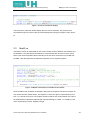
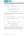
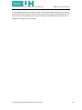
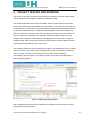
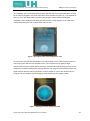
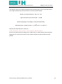
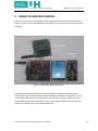
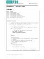
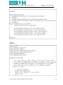
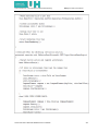
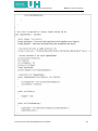
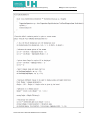
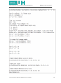
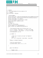
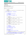
(UH) University of Hertfordshire School of Electronic, Communication and Electrical Engineering BACHELOR OF ENGINEERING DEGREE WITH HONOURS IN ELECTRICAL AND ELECTRONIC ENGINEERING Final Year Project Report i.MXS ARM-BASED DIGITAL COMPASS Report by: Sheraz Khan Malik Supervisor: Kate Williams APRIL 2008 DECLARATION STATEMENT I certify that the work submitted is my own and that any material derived or quoted from the published or unpublished work of other persons has been duly acknowledged (ref. UPR AS/C/6.1, Appendix I, Section 2 – Section on cheating and plagiarism) Student Full Name: Sheraz Khan Malik Student Registration Number: 04106220 Signed: ………………………………………………… Date: 07 April 2008 School of Electronic, Communication and Electrical Engineering BEng Final Year Project Report ABSTRACT This report holds the detailed information about how to design an i.MXS ARM BASED DIGITALL COMPASS. To complete the task a Tahoe development platform was used which was provided by the university. It operates with VS.NET Micro Framework software and runs with an input of 5V. To achieve the compass characteristic a magnetic sensor was used provided by the university. It was interfaced with the I2C bus on the Tahoe board, and to make the compass fully working a programme code was developed using VS.NET Micro Framework software with the help of sample codes. The output was obtained as a digital compass and to make it look even better a GUI was created by making modifications to the same code. Sheraz Khan Malik /i.MXS ARM BASED DIGITAL COMPASS i School of Electronic, Communication and Electrical Engineering BEng Final Year Project Report ACKNOWLEDGEMENTS I would like to express my gratitute and appreciation to my project supervisor, Kate Williams for encouraging me for my work with her advice and moral support. I would also like to thank Mr John Willmort in Lab c-460, who provided peaceful working environment, and helped me regarding general problems in the project lab. Finally I would like to thank my parents as well as my friends Owais, Tafseer, Saad, Bilal and Gurpreet who encouraged me throughout my project. Sheraz Khan Malik /i.MXS ARM BASED DIGITAL COMPASS ii School of Electronic, Communication and Electrical Engineering BEng Final Year Project Report TABLE OF CONTENTS DECLARATION STATEMENT ........................................................................................................i ABSTRACT .....................................................................................................................................i ACKNOWLEDGEMENTS .............................................................................................................. ii TABLE OF CONTENTS ................................................................................................................ iii LIST OF FIGURES .........................................................................................................................v GLOSSARY ................................................................................................................................... vi 1. 2. 3. INTRODUCTION .................................................................................................................. 1 1.1 PROJECT AIM AND OBJECTIVE ................................................................................ 1 1.2 RESEARCH .................................................................................................................. 1 1.2.1 TAHOE DEVELOPMENT KIT ............................................................................... 1 1.2.2 TAHOE BOARD .................................................................................................... 2 1.2.3 SOFTWARE .......................................................................................................... 3 1.2.4 MAGNETIC SENSOR ........................................................................................... 5 HARDWARE ......................................................................................................................... 6 2.1 CMPS03 ........................................................................................................................ 6 2.2 I2C INTERFACING ....................................................................................................... 7 2.3 CONNECTING HARDWARE ............................................................................................ 9 CODING ............................................................................................................................. 12 3.1 Program.cs .................................................................................................................. 12 3.2 LCD.cs ......................................................................................................................... 14 3.2.1 Class Compass Element ....................................................................................... 15 3.2.2 Class Intro Screen ................................................................................................ 19 3.3 BusIO.cs ...................................................................................................................... 20 3.4 Sensor.cs .................................................................................................................... 22 4. PROJECT TESTING AND WORKING ............................................................................... 24 5. RESULTS AND DISCUSSION ........................................................................................... 27 6. EVALUATION ..................................................................................................................... 29 7. CONCLUSION & FURTHER DEVELOPMENT .................................................................. 30 REFERENCES ............................................................................................................................ 31 BIBLIOGRAPHY.......................................................................................................................... 32 APPENDIX.1 PROJECT CODE .................................................................................................. 33 Program.cs .................................................................................................................................. 33 LCD.cs ......................................................................................................................................... 34 BusIO.cs ...................................................................................................................................... 40 Sensor.cs .................................................................................................................................... 42 APPENDIX.2 SAMPLE CODE .................................................................................................... 44 Sheraz Khan Malik /i.MXS ARM BASED DIGITAL COMPASS iii School of Electronic, Communication and Electrical Engineering BEng Final Year Project Report CMPS03Compass.cs .................................................................................................................. 44 I2CSlave.cs ................................................................................................................................. 48 Endianity.cs ................................................................................................................................. 52 Sheraz Khan Malik /i.MXS ARM BASED DIGITAL COMPASS iv School of Electronic, Communication and Electrical Engineering BEng Final Year Project Report LIST OF FIGURES Figure 1- Tahoe Board .................................................................................................................. 2 Figure 2- Block diagram Meridian CPU........................................................................................ 3 Figure 3- IDE for VS.NET 2005 ................................................................................................... 4 Figure 5- I2C Bus Terminology ................................................................................................... 8 Figure 6- Project Hardware Components ................................................................................... 10 Figure 7- Project Block diagram ................................................................................................ 11 Figure 8- Class diagram for Program code ............................................................................... 12 Figure 9- Program.cs code for main window ............................................................................ 12 Figure 10- Program.cs code for button definitions .................................................................... 13 Figure 11- LCD.cs showing Private variables ........................................................................... 14 Figure 12- LCD.cs showing override event ................................................................................ 14 Figure 13- LCD.cs Reloading intro screen using else statement ............................................... 15 Figure 14- Compass Screen ...................................................................................................... 15 Figure 15- LCD.cs Compass screen display .............................................................................. 16 Figure 16 (a)- Picture used for angle and direction .................................................................... 16 Figure 16 (b)- Picture for analog compass display .................................................................... 16 Figure 17- LCD.cs Calculating screen centre points .................................................................. 17 Figure 18- LCD.cs array method for direction ............................................................................ 17 Figure 19- LCD.cs Calculating directions ................................................................................... 17 Figure 20- LCD.cs Drawing compass needle ............................................................................ 18 Figure 21- Intro screen for compass .......................................................................................... 19 Figure 22- LCD.cs Intro screen display ...................................................................................... 20 Figure 23- BusIO.cs Declaration of variables and constants ..................................................... 20 Figure 24- BusIO.cs Read operations ........................................................................................ 21 Figure 25- BusIO.cs Write operations ........................................................................................ 21 Figure 26- Sensor.cs showing address of register and sensor bus ........................................... 22 Figure 27- Sensor.cs Getting compass heading ........................................................................ 22 Figure 28- IDE showing debug window...................................................................................... 24 Figure 29- Compass intro screen displayed in LCD .................................................................. 25 Figure 30- Compass screen displayed on LCD ......................................................................... 25 Figure 31- Working compass intro screen ................................................................................. 27 Figure 32- Working compass screen display ............................................................................. 28 Sheraz Khan Malik /i.MXS ARM BASED DIGITAL COMPASS v School of Electronic, Communication and Electrical Engineering BEng Final Year Project Report GLOSSARY ARM: It stands for Acorn RISC Machines, which is a 32 bit RISC (Reduced instruction set computer) architecture developed by ARM Limited that is widely used by a number of embedded designs. i.MXS: It is the name of microprocessor designed by Freescale and operates at speed of 100MHz. SDRAM: Synchronous Dynamic Random Access Memory, type of solid state computer memory. RISC: Stands for Reduced Instruction Set Computer GUI: Graphical user interface. It allows people to interact with a computer and computer controlled devices. GPS: Global Positioning System is a navigation precise-positioning tool uses satellites to determine position of the subject worldwide. [1] VS.NET: Visual Studio.NET is software based programming language also known as c-sharp, it is used to develop console and GUI applications along with windows applications. [2] Console: Console application is a computer program designed to be used by the text only computer interface. [3] SDK: Software development kit is a set of development tools which allow a user or a software engineer to create applications for a specific software package. Emulator: An emulator is the software used to perform emulation of the hardware used by a system. Emulation is the simulation of silicon chips or integrated circuits used in a hardware system using computer software. [4] SPI: Serial peripheral interface bus is a simple Master/Slave 4 wire protocol one for synchronous clock (SCL), one for data transmitting, one for data receive and another for chip select. Chip Select: It is a control line that selects one chip out of several connected to the same computer bus. GPIO: General purpose input/output pins. UART: Universal Asynchronous Receiver/Transmitter controller is the key component of the serial communications subsystem of a computer. The UART takes bytes of data and transmits the individual bits in a sequential fashion. At the destination, a second UART re-assembles the bits into complete bytes. [5] IDE: Integrated development environment. EEPROM: Electronically Erasable Programmable Read Only Memory. Sheraz Khan Malik /i.MXS ARM BASED DIGITAL COMPASS vi School of Electronic, Communication and Electrical Engineering BEng Final Year Project Report 1. INRODUCTION The project involves designing an i.MXS ARM Based Digital Compass. Digital compasses have a great importance in today’s world. The modern technology has empowered mankind to travel distant places. Compasses have played a vital role in many ways and are still being used with a great importance. The people from the old age used different ways to direct them towards their destinations. Compasses have made this job easier for today’s generation. They are being used in aircrafts, robots, navigation systems, GPS receivers, sports watches, submarines and etc. This report contains various stages of work involved in designing the digital compass and all the techniques and methodology used to achieve the required result. 1.1 PROJECT AIMS AND OBJECTIVES The project aim was to design an I.MXS ARM Based Digital Compass with the help of the provided Tahoe development kit and selecting a suitable magnetic sensor. The objective of the project was to display output of the digital compass on the Tahoe board by interfacing it with a suitable magnetic sensor, and using the VS.NET Micro Framework software. 1.2 RESEARCH The project research stage was to develop understanding for the steps involved in design and working of digital compasses. The research process was carried out in order to understand the working of the hardware as well as designing the software, which was achieved by using internet and web based data. The main purpose of research stage was to get all the basic information about the project and understand the steps involved in developing a digital compass using the provided components. 1.2.1 TAHOE DEVELOPMENT KIT The Tahoe development kit was provided by the university. The Tahoe platform provides an ideal development system for Meridian CPU and .NET Micro Framework. The Tahoe platform includes; 1- Tahoe Board. 1- USB cable. A VS.NET 2005 installation disk. SDK with customise emulator for .NET Micro Framework. Sheraz Khan Malik /i.MXS ARM BASED DIGITAL COMPASS 1 School of Electronic, Communication and Electrical Engineering 1.2.2 BEng Final Year Project Report TAHOE BOARD The Tahoe board is a fully functional system allowing an infinite variety of expansion via support for serial, SPI and I2C communications. Shown below is the Figure of the Tahoe board. [6] Figure -1 Tahoe Board The technical [6] [6] specifications of the board are as follows; Core: Embedded Fusion Meridian CPU It is a microprocessor mounted at the back of the Tahoe platform operates at 100MHz. It has a 2MB flash and 8MB SDRAM. GPIO: Most pins are configurable as GPIO if not used for other purposes Minimum of 16 GPIO Pins Available (up to 64) Communication and expansion busses: 1x UART RS-232 DB9 connector I2C for external peripherals SPI Bus (can use GPIOs for ―chip selects‖ if required) USB Function (for application download and debug) Timers and clocks: timer output Optional input for programmable timer (can use internal clock) Pulse width modulator (PWM) Sheraz Khan Malik /i.MXS ARM BASED DIGITAL COMPASS 2 School of Electronic, Communication and Electrical Engineering BEng Final Year Project Report Power supply: 5V input Allows powering direct from USB Function port (no additional supply needed) 3.3V outputs for peripherals. Shown below is the block diagram for Meridian CPU; Figure – 2 Block diagram for Meridian CPU 1.2.3 SOFTWARE The software used for the project was VS.NET Micro Frame Work (Version 2005), the Tahoe board is compatible with this software. The .NET Micro Framework [7] is Microsoft's latest implementation of the .NET Common Language Runtime (CLR). The most notable aspect of the .NET Micro Framework is that it does not need any underlying operating system. The Micro Framework requires very little in the way of system resources thus reducing the overall cost of a system. (The minimum memory resources are about 384K of FLASH/ROM and 256K of RAM) The Micro Framework first appeared in the MSN Direct Smart Personal Object Technology (SPOT) watches and devices. In May of 2006 Microsoft announced it would make the .NET Micro Framework available to the general embedded community through hardware partners. The most noticeable use of the Micro Framework so far is the Windows Sideshow compatible devices built into many new laptops for Windows Vista. Sheraz Khan Malik /i.MXS ARM BASED DIGITAL COMPASS [7] 3 School of Electronic, Communication and Electrical Engineering The .NET Micro Framework [7] BEng Final Year Project Report consists of two parts the Common Language Runtime and the Core Libraries. The Common Language Run time is a system, designed by Microsoft that executes Microsoft Intermediate Language or MSIL instructions. The software is provided with an SDK called ―Tahoe SDK‖ that plugs directly into Visual Studio 2005 and applications can be written directly in C# for CPUs with the .NET Micro Framework. The Core Libraries provided in the SDK are an extended sub set of the framework available on the desktop. The .NET Micro Framework adds many specialized components designed for small, low power 2 embedded systems like I C, and SPI. [7] The figure-3 shows a working view of the VS.NET 2005 software used in the project; Figure – 3 IDE for VS.NET 2005 The Micro Framework [7] offers embedded systems developers a line of CPUs that essentially directly execute MSIL. There is no need for low level assembly language or other proprietary languages. You can use the standardized C# language to implement a complete embedded system from handling interrupts to displaying a rich Graphical User Interface (GUI). Sheraz Khan Malik /i.MXS ARM BASED DIGITAL COMPASS [7] 4 School of Electronic, Communication and Electrical Engineering 1.2.4 BEng Final Year Project Report MAGNETIC SENSOR In the project one of the important tasks was to decide which magnetic sensor must be used for compassing as there were a lot of magnetic sensors available in market. There was a variety of magnetic sensors available for compassing depending upon their output including 1-axis, two-axis and three-axis magnetic sensors. Magnetic sensors [8] detect changes, or disturbances, in magnetic fields that have been created or modified, and from them derive information on properties such as direction, presence, rotation, angle, or electrical currents. The output signal of these sensors requires some signal processing for translation into the desired parameter. Although magnetic detectors are somewhat more difficult to use, they do provide accurate and reliable data — without physical contact. A magnetic field is a vector quantity with both magnitude and direction. The scalar sensor measures the field's total magnitude but not its direction. The omnidirectional sensor measures the magnitude of the component of magnetization that lies along its sensitive axis. The bidirectional sensor includes direction in its measurements. The vector magnetic sensor incorporates two or three bidirectional detectors. Some magnetic sensors have a built-in threshold and produce an output only when it is surpassed. Sheraz Khan Malik /i.MXS ARM BASED DIGITAL COMPASS [8] 5 School of Electronic, Communication and Electrical Engineering BEng Final Year Project Report 2. HARDWARE The hardware part of the project involved connecting the suitable magnetic sensor to the Tahoe board. The selection of magnetic sensor was not an easy job as there were a lot of varieties of magnetic sensor available. The selection criteria were based on the sensor output, whereas the required output for sensor was to be digital, which means that an ADC (Analog to Digital Converter) was also required as a part of hardware. As from the name it suggests that an ADC converts an analog signal into digital signal. The magnetic sensor chosen for this project was the CMPS03. 2.1 CMPS03 OVERVIEW: The CMPS03 is a two-axis compass module (sensor board). It is called a compass module as it is SOC (system on a chip) itself. The compass [9] uses the Philips KMZ51 magnetic field sensor, which is sensitive enough to detect the Earth’s magnetic field. The output from two of them mounted at right angles to each other is used to compute the direction of the horizontal component of the Earth’s magnetic field. The compass also has an ADC which converts the analog signal into digital signal. Shown below is the figure for CMPS03 showing direction for its true north and its connections; [9] Figure – 4 CMPS03 (connections) Sheraz Khan Malik /i.MXS ARM BASED DIGITAL COMPASS [9] 6 School of Electronic, Communication and Electrical Engineering BEng Final Year Project Report PIN CONNECTIONS: Pin 1 +5 V. The compass module requires a 5v power supply at a nominal 15mA. There are two ways of getting the bearing from the module. A PWM signal is available on pin 4, or an I2C interface is provided on pins 2, 3. [9] Pin 2, 3 are an I2C interface and can be used to get a direct readout of the bearing. If the I2C interface is not used then these pins should be pulled high (to +5v) via a couple of resistors. Around 47k is ok, the values are not at all critical. [9] Pin 4. The PWM signal is a pulse width modulated signal with the positive width of the pulse representing the angle. The pulse width varies from 1mS (0°) to 36.99mS (359.9°) – in other words 100uS/° with a +1mS offset. The signal goes low for 65mS between pulses, so the cycle time is 65mS + the pulse width - i.e. 66ms-102ms. The pulse is generated by a 16 bit timer in the processor giving a 1uS resolution. It was to be made sure that the I2C pins, SCL and SDA, were connected to the 5v supply if PWM was used, as there are no pull-up resistors on these pins. [9] Pin 5 is used to indicate calibration is in progress (active low). An LED can be connected from this pin to +5v via a 390 ohm resistor if user wishes. [9] Pin 6 is one of two ways to calibrate the compass, the other is writing 255 (0xFF) to the command register. The calibrate input has an on-board pull-up resistor and can be left unconnected after calibration. [9] Pins 7 and 8 are left unconnected as they have on board pull-up resistors. Pin 9 is ground 0V power supply. 2.2 I2C INTERFACING The I2C bus is a two wired bus serial data line (SDA) and serial clock line (SCL), usually to interact within small number of divisions. It can operate at different speeds 100kbps (standard mode), 400kbps (fast mode) and 3.4Mbps (high speed mode).The data transfer in I2C bus is bi-directional and is 8-bit oriented and is in form of serial data. On an I2C-bus any I2C device can be attached and every device can talk with any master, passing information forward and backward. Each device [10] has a unique 7-bit I2C address so that the master knows specifically whom they are communicating with. Typically the four most significant bits are fixed and assigned to specific categories of devices. Sheraz Khan Malik /i.MXS ARM BASED DIGITAL COMPASS 7 School of Electronic, Communication and Electrical Engineering BEng Final Year Project Report The three less significant bits are programmable through hardware address pins allowing up to eight different I2C address combinations and therefore allowing up to eight of that type of device to operate on the same I2C-bus. These pins are held high to VCC (1) or held low to GND (0). 7-bit addressing allows up to 128 devices on the same bus but some of these addresses are reserved for special commands so the practical limit is around 120. [10] Shown below is the diagram of the I2C bus terminology; Figure – 5 I2C Bus Terminology [10] Master device controls the SCL, starts and stops the data transfer and controls the addressing of the other devices. Slave device itself is addressed by the Master. In case of the data transmitting and receiving that Master-transmitter sends data to the slave-receiver and the Master-receiver requires data from the Slave-transmitter. The data bits are transferred after start condition. The data transmission is byte oriented where; 1 byte = 8bit + one acknowledge bit The most significant bit (MSB) always comes first. During the first byte transfer Master is transmitter and address slave is receiver. Sheraz Khan Malik /i.MXS ARM BASED DIGITAL COMPASS 8 School of Electronic, Communication and Electrical Engineering BEng Final Year Project Report I2C communication Protocol with the Compass module is same as the popular EEPROM’s. The compass module has a 16 byte array of registers, some of which double up as 16bit registers are as follows; Register Function 0 Software Revision number 1 Compass Bearing as a byte, i.e. 0-255 for a full circle 2, 3 Compass Bearing as a word, i.e. 0-3599 for a full circle, representing 0-359.9 degrees. 4, 5 Internal Test - Sensor1 difference signal - 16 bit signed word 6, 7 Internal Test - Sensor2 difference signal - 16 bit signed word 8, 9 Internal Test - Calibration value 1 - 16 bit signed word 10, 11 Internal Test - Calibration value 2 - 16 bit signed word 12 Unused - Read as Zero 13 Unused - Read as Zero 14 Unused - Read as Undefined 15 Command Register Table showing functions of compass module registers. Register 0 is [9] the Software revision number (8 at the time of writing). Register 1 is the bearing converted to a 0-255 value. This may be easier for some applications than 0-360 which requires two bytes. For better resolution registers 2 and 3 (high byte first) are a 16 bit unsigned integer in the range 0-3599. This represents 0-359.9°. Registers 4 to 11 are internal test registers and 12, 13 are unused. Register 14 is undefined. There is no need to read them it would do nothing but waist the I2C bandwidth. Register 15 is used to calibrate the compass. 2.3 CONNECTING HARDWARE The hardware connections were made according to the provided data sheet of the compass module and the user manual given with the Tahoe board. The equipment used for the hardware connections were as follows; 1-Soldering iron. 6- Coloured wires. 2- Connecting headers. Sheraz Khan Malik /i.MXS ARM BASED DIGITAL COMPASS 9 School of Electronic, Communication and Electrical Engineering BEng Final Year Project Report The compass module was not directly soldered on the I2C bus of the Tahoe board. Two headers were used in order to prevent direct contact of the soldering iron to the Tahoe board and the compass module (sensor board). Different coloured wires were used to differentiate the connections. Initially all the wires were soldered on to the connecting headers in order to avoid any damage to the sensor board or the Tahoe board. Red coloured wire was used for 5V connection and black for the 0V ground. Pin1 +5V of the sensor board was connected to the +5V on the I2C bus and Pin9 0V ground was connected to the 0V ground of the I2C bus. Pins 2 (SCL) and 3 (SDA) of the compass module were connected to the SCL and SDA pins of the I2C bus on the Tahoe board. Yellow colour wire was used for SCL and purple colour wire was used for SDA. Pink and brown coloured wires were used for pin 5 and 6 but they were left un-connected according to the given connections. The pin 6 was to be calibrated but it was left un-connected as the calibration was done through the software. Shown below is the picture of all the hardware components involved; Figure – 6 Project Hardware components It was made sure that all the connections were accurate according to the data sheet before powering the board as it could result in damaging the board. Extra care was taken while handling the compass module as it was sensitive to static charge. In order to avoid that anti static wrist band was used which was provided in the laboratory to avoid the hazard of static charge. Sheraz Khan Malik /i.MXS ARM BASED DIGITAL COMPASS 10 School of Electronic, Communication and Electrical Engineering BEng Final Year Project Report Shown below is the block diagram of the project hardware part, showing all the connections from the sensor board to the I2C bus on the Tahoe board. Figure – 7 Project Block Diagram Problems faced during the hardware connection were as follows; Lose connection due to weak soldering. An inverted connection, SDA of the sensor board was connected to the SCL of the Tahoe board. One of the headers was damaged with the soldering iron, which was then replaced with a new one. Sheraz Khan Malik /i.MXS ARM BASED DIGITAL COMPASS 11 School of Electronic, Communication and Electrical Engineering BEng Final Year Project Report 3. CODING This section of the report contains the detailed explanation of the programe code developed for the project. For complete copy of the code as well as the sample code please refer to the Appendix. The programe code was developed by looking at different examples of basic clanguage code regarding compassing and the sample code provided with the sensor board. The programe code was divided into four main classes. The class diagram shown below gives an overview about overall working of the programe code. Figure – 8 Class diagram for Programe code 3.1 Program.cs The Program.cs class runs the main window application and also checks for the button definitions. Figure – 9 Program.cs code for main window Sheraz Khan Malik /i.MXS ARM BASED DIGITAL COMPASS 12 School of Electronic, Communication and Electrical Engineering BEng Final Year Project Report It shows in figure-9, that this class allows to initiate and run the main window application. The main window application is like a starting point for the class. Figure – 10 Program.cs code for button definitions The above figure-10 is showing the button definition part of the class Program.cs. In this part of Program.cs the buttons on the Tahoe board are accessed with the help of the program code. It shows that the functioning button is the ―Select‖ button which is named as SW7, and in the programe code it shows that it checks for all the buttons and gets value ―True‖. Whereas on button SW7 it gets ―False‖ this allows it to jump towards the next step. It is not necessary to define all the buttons. Only the required button can also be defined but it is done for demo purposes. Sheraz Khan Malik /i.MXS ARM BASED DIGITAL COMPASS 13 School of Electronic, Communication and Electrical Engineering 3.2 BEng Final Year Project Report LCD.cs The LCD.cs class inherits window class which is inbuilt class of the SDK. This class is responsible to show any button activity and show different images and text (GUI) to be displayed on the screen. The LCD class is further divided into two sub classes for different screens. LCD class is important class as it holds all the GUI elements and is responsible to show all the text and image activity. Figure – 11 LCD.cs code showing Private variables In figure-11 the LCD class window is defining variables, which give the font size, background colour and create a new intro screen on the LCD of the Tahoe board. The intro.StartRendering allows the text to be printed on the screen. Figure – 12 LCD.cs code showing override event Sheraz Khan Malik /i.MXS ARM BASED DIGITAL COMPASS 14 School of Electronic, Communication and Electrical Engineering BEng Final Year Project Report The figure-12 shows the override event for the button activity using ―if/else‖ statements. The override event is used in order to make changes into the start rendering event. The start rendering event has a default method of printing text. Override event provides user to play with the start rendering function and change it as required. It shows that the override event detects the button action and responds accordingly if the rite button is pressed it will exit the intro screen and load the compass view screen. Figure – 13 LCD.cs Reloading intro screen using else statement In above figure-13 it is showed that if the wrong button is pressed the program will invalidate the compass view screen and load the intro screen again using the ―else‖ statement. The LCD class has further two sub classes explained below. 3.2.1 Class Compass Element The class compass element displays the compass reading and compass screen on to the LCD of the Tahoe board. In this class the different images are displayed on to the compass screen. The compass screen obtained is shown below; Figure – 14 Compass Screen Sheraz Khan Malik /i.MXS ARM BASED DIGITAL COMPASS 15 School of Electronic, Communication and Electrical Engineering BEng Final Year Project Report Figure – 15 LCD.cs code compass screen display The figure-15 shows how to display any bitmap image. Any Bitmap file can be displayed using these lines of code; any bitmap file present in the resource folder of the programe can be displayed by using this part of the program code. The picture format can be Bitmap as well as JPEG. The above piece of code is simply accessing the bitmap files from the resources and displaying them as image on the LCD for compass and angle. The images used are shown below, Figure – 16(a) Picture used for angle and direction The figure-16(a) shows the picture used to display the angle of the compass as well as the direction. Figure – 16(b) Picture for analog compass display Sheraz Khan Malik /i.MXS ARM BASED DIGITAL COMPASS 16 School of Electronic, Communication and Electrical Engineering BEng Final Year Project Report The picture (figure-16(b)) was used for analog compass display with the help of the program code explained above and showed in figure-15. Both these images (16a, 16b) were displayed on the screen but before doing that the centre points of the screen were calculated which can be shown in the figure-16 below. Figure – 17 LCD.cs Calculating screen centre points The compass direction was displayed by using array method. The compass direction was divided in 16 directions between 0’ to 360’which gives a value of 22.5.That means the compass direction must change after every 22.5’ degrees. The array was assigned with 16 numbers. Figure – 18 LCD.cs array method for direction The process was very simple. On getting the angle value from the sensor board, the value was then divided with the calculated value 22.5. It gives a number between 1- 16 and depending on the number the array displays the direction. The figure-18 below shows the piece of code for the process explained. Figure – 19 LCD.cs Calculating directions The last two lines of the code in figure-19 are drawing text for angle and direction on the screen with a selected green colour and also calculating the points where the text should be displayed or in other words the parameters for the text and angle. The direction calculation can be shown for example if we assume the angle value to be 45’ degrees. Sheraz Khan Malik /i.MXS ARM BASED DIGITAL COMPASS 17 School of Electronic, Communication and Electrical Engineering BEng Final Year Project Report We have; Calculated value for directions = 22.5 =2 Hence the calculated direction will be NE (North East) as it is the 2 nd number direction from the left hand side if you see figure-17. The calculated value is passed to array and the string then display’s the direction that comes on that number which is 2. So that means the compass should be pointing at NE (North East) at an angle of 45’ degrees. Figure – 20 LCD.cs Drawing Compass needle The program code shown in above figure-20 is drawing the compass needle. The compass needle was drawn using the Math function for drawing vector. North was used to calibrate the compass it was given an off -set value of 90. So the default position of the compass angle was 90.The compass needle was to be drawn according to the clock radius of the blue circle in the compass picture shown in figure-16(b). It was approximately 50 pixels. Sheraz Khan Malik /i.MXS ARM BASED DIGITAL COMPASS 18 School of Electronic, Communication and Electrical Engineering BEng Final Year Project Report The value of the clock radius was first defined at the top of the program code in Private variables. The compass needle was then drawn by taking Cos and Sine of the compass angle. Initially it resulted in a big value giving the compass needle an abnormal length. To avoid this calculated value was then divided by 1000 to get it to unity. As we know that the value for Sine and Cos is between 0-1, after that it was then multiplied by 50 (clock radius), which controlled the length of the compass needle according to the clock radius of the blue circle. To obtain the full length of the compass needle the same code was used by adding a negative sign to it which gave a compass needle of similar length but on the opposite direction. To differentiate the opposite side its colour was changed to black 3.2.2 Class Intro Screen As from the name it shows that this class is responsible for loading the intro screen onto the LCD screen of the Tahoe board. The same lines of code were used for this class as discussed before in figure-15. Shown below is the picture of the intro screen of the compass. Figure – 21 Intro Screen for compass Sheraz Khan Malik /i.MXS ARM BASED DIGITAL COMPASS 19 School of Electronic, Communication and Electrical Engineering BEng Final Year Project Report Figure – 22 LCD.cs Intro Screen display The exact same code was used to display the intro screen elements. The pictures were accessed through the resource files and were displayed by using the program code in figure21. 3.3 BusIO.cs The BusIO.cs class is responsible for I2C communication protocol between the software and the hardware. The class allows the software to communicate with the I2C bus of the Tahoe board. This class manipulates the functionality of the I2C slave class which is provided with the SDK. This class performs the read/write operation on the required registers. Figure – 23 BusIO.cs Declaration of variables and constants All the variables and constants are defined in this piece of programe code shown in figure-23. The values used are default values. The register 1 is used as it gives compass bearing as a byte, i.e. 0-255 for a full circle. The register numbers used for I2C communication are 2 and 3 as explained above that these registers get compass bearing as a word, i.e. 0-3599 for a full circle, representing 0’-359.9’ degrees in angle. Sheraz Khan Malik /i.MXS ARM BASED DIGITAL COMPASS 20 School of Electronic, Communication and Electrical Engineering BEng Final Year Project Report Figure – 24 BusIO.cs Read operations In the above (figure-24) part of the program code the BusIO class is to read any port on the I2C bus of the Tahoe board. Execute method will read bytes on the I2C bus and returns the number of bytes successfully on the bus. Figure – 25 BusIO.cs Write operations In figure-25 the program code writes the port on the I2C bus. The Execute method here will write bytes on the I2C bus and returns the number of bytes successfully on the bus. The process taking place in this part of code is similar to the one explained for code in figure-24 the only difference is that this time the code is performing the write operation instead of read operation. Sheraz Khan Malik /i.MXS ARM BASED DIGITAL COMPASS 21 School of Electronic, Communication and Electrical Engineering 3.4 BEng Final Year Project Report Sensor.cs The sensor class implements the functionality of the sensor board to read the compass values in degrees. Figure – 26 Sensor.cs showing address of register and sensor bus This part of the program code (Figure-26) assigns address to the sensor bus. The address used is 60 as it was the default address given for the sensor board. In the next step the compass heading is taken from the register 2. As explained above the register 2 and 3 get compass bearing as a word i.e. 0-3599 for a full circle representing 0’- 359.9’ degrees of angle. Figure – 27 Sensor.cs getting compass heading This section of program code (Figure-27) gets the Azimuth value from the sensor board and then reads the register value when it is high into the data buffer. The next step it shows that the byte order is set using Big Endian. Sheraz Khan Malik /i.MXS ARM BASED DIGITAL COMPASS 22 School of Electronic, Communication and Electrical Engineering BEng Final Year Project Report The Big Endian means the big end first, which means that the high order bytes are stored first into the low memory location. Then it converts the receiving bytes into float (decimal) type and returns the value to the calling function. If the condition is not satisfied then it uses the ―else‖ statement to display an error message. Sheraz Khan Malik /i.MXS ARM BASED DIGITAL COMPASS 23 School of Electronic, Communication and Electrical Engineering BEng Final Year Project Report 4. PROJECT TESTING AND WORKING This section of the report contains the project testing on hardware as well as software basis, and the problems faced during the software and hardware testing. The hardware was tested with the help of software. All the communication and expansion buses of the Tahoe board were tested at very initial stage to confirm that the board itself was working perfectly. This was done by running default test programs provided with the software for the each communication bus. It helped in understanding the nature of the hardware as well as the software. In hardware there were problems faced during testing of the SPI bus it kept on showing error messages which was then rectified by making changes to the test program code. It helped in understanding the debugging process which later on helped in software testing. After connecting the sensor board with Tahoe board the software was then tested before the final testing of the whole project. The software testing was carried throughout the program code development process. Initially there were errors in the program code. Debugging was carried out constantly to make sure that the program code was correctly working before testing it with the hardware. The debugging process helped in error diagnosis and also helped in understanding the csharp language limitations. Figure – 28 IDE showing debug window After completing the testing process for hardware and software the whole project was then tested to get the required results. Sheraz Khan Malik /i.MXS ARM BASED DIGITAL COMPASS 24 School of Electronic, Communication and Electrical Engineering BEng Final Year Project Report The hardware was connected to the PC/Laptop with the help of provided USB cable. As soon as the cable is plugged in the power light of the Tahoe board turns green (on). The software is then run. Once the debug button is pressed the program code is build and debugged completely. After completing the debug process the intro screen appears on the LCD of the Tahoe board telling the user to press button SW7 to start. Figure – 29 Compass intro screen displayed on LCD As soon as the user hits the SW7 button or the select button on the Tahoe board it moves on to the next screen which is the compass screen. The compass screen displays angle measured by the sensor board and the directions calculated through the program code. It also displays the compass needle which changes direction with respect to the changing angle. The angle changes with the change in direction of sensor board i.e. right or left. Shown below is the picture of the compass screen displaying angle, direction and compass needle. Figure – 30 Compass screen displayed on LCD Sheraz Khan Malik /i.MXS ARM BASED DIGITAL COMPASS 25 School of Electronic, Communication and Electrical Engineering BEng Final Year Project Report The direction name and compass needle direction showed in figure-30 is correct with respect to the angle measured by the sensor board. It can be proved as follows; Number of compass direction = 360 / 16 = 22.5 Angle measured by the sensor board = 119.8 Direction appearing on the display = ESE (East South East) Measured angle / compass direction = 119.8 / 22.5 = 5.3, Approx 5 Whereas the divided direction names are; N,NNE,NE,ENE,E,ESE,SE,SSE,S,SSW,SW,WSW,W,WNW,NW,NNW,N th Hence out of these directions starting from 0, ESE is the 5 number direction which has been displayed on the LCD screen and even the compass needle is pointing towards the same direction. Sheraz Khan Malik /i.MXS ARM BASED DIGITAL COMPASS 26 School of Electronic, Communication and Electrical Engineering BEng Final Year Project Report 5. RESULTS AND DISCUSSION This section of the report contains all the results obtained at the testing and implementation stage f the project. The results obtained were as expected and were satisfying the objective of the project. Figure – 31 Working Compass intro screen The figure-29 is showing the picture of the whole project running and displaying the intro screen, which shows that the software and the hardware are working correctly. Also it can be seen that the sensor board is connected to the Tahoe board. The button labelled as SW7 is the select button which allows the user to move on to compass screen by pressing it. These pictures were taking at the project demonstration time. Sheraz Khan Malik /i.MXS ARM BASED DIGITAL COMPASS 27 School of Electronic, Communication and Electrical Engineering BEng Final Year Project Report Figure – 32 Working Compass screen displayed Figure-30 shows the working display of the project as Digital Compass. It can be seen that the angle is displayed in degrees and the name of the direction is also displayed. Also the compass needle is pointing in the direction displayed. From the results it can be seen that the project was a success in terms of achieving the required task. It meets the brief of, developing an i.MXS ARM Based Digital Compass device that directs the user towards the wanted direction based on its true north. The results also justify all the details explained above in the report regarding the project. Sheraz Khan Malik /i.MXS ARM BASED DIGITAL COMPASS 28 School of Electronic, Communication and Electrical Engineering BEng Final Year Project Report 6. EVALUATION The projects meets the requirements for i.MXS ARM Based Digital Compass. Project was completed within the specified time without facing any high level difficulties. The project satisfies the requirement of an i.MXS ARM Based Digital Compass. The device created can be used in different applications such as aircrafts, robots, Navigation systems, GPS receivers and etc. Although the project did not exactly followed the time plan provided in the feasibility study, due to some delays in the progress but it was completed before the given time. Sheraz Khan Malik /i.MXS ARM BASED DIGITAL COMPASS 29 School of Electronic, Communication and Electrical Engineering BEng Final Year Project Report 7. CONCLUSION & FURTHER DEVELOPMENT The project satisfied the requirements of an i.MXS ARM Based Digital Compass. This project helped in improving learning skills and provided a chance of enhancing knowledge. It helped in understanding the basic concepts of digital compasses, and the background knowledge about the magnetic sensors and their operations. It also improved the skills in learning csharp programming language. The projects requirements were; To design an i.MXS ARM Based Digital Compass. To display digital compass output on the Tahoe board using magnetic sensor and VS.NET Micro Framework software. The project achievements were; An i.MXS ARM Based Digital Compass was designed. The output of Digital compass was displayed on LCD of Tahoe board using sensor board and VS.NET Micro Framework software. For future development it was decided that an off-set window will be introduced in the digital compass. The output window will allow any user to set their true north according to their requirement. For example if a user thinks that the true north showed by the compass has an error of about 5 degrees. The user will press the selected button for the off-set window. A new screen will appear asking the user to enter off-set value. This off set window will appear after the second screen which is the compass screen or it could be accessed any time while the compass is running by pressing the selected button. After entering the off-set value the user will be able set the true north as required. Sheraz Khan Malik /i.MXS ARM BASED DIGITAL COMPASS 30 School of Electronic, Communication and Electrical Engineering BEng Final Year Project Report REFERENCES Reference Number Reference Link [1] http://scign.jpl.nasa.gov/learn/gps1.htm [2] http://en.wikipedia.org/wiki/Vs.net [3] http://en.wikipedia.org/wiki/Console_application [4] http://www.mameworld.net/easyemu/emuwhatis.htm [5] http://www.freebsd.org/doc/en_US.ISO8859-1/articles/serial-uart/index.html [6] http://www.embeddedfusion.com/uploadedFiles/products/TahoeDetailSheet.pdf [7] http://www.embeddedfusion.com/default.aspx?id=76 [8] http://www.sensorsmag.com/articles/0399/0399_18/ [9] http://www.robot-electronics.co.uk/htm/cmps3tech.htm [10] http://www.nxp.com/products/interface_control/i2c/facts/ [11] http://www.robot-electronics.co.uk/acatalog/examples.html Sheraz Khan Malik /i.MXS ARM BASED DIGITAL COMPASS 31 School of Electronic, Communication and Electrical Engineering BEng Final Year Project Report BIBLIOGRAPHY BOOKS TITLE AUTHOR 1 Visual C# 2005 a developer’s notebook. JESSE LIBERTY 2 Programming C# Jesse Liberty JESSE LIBERTY 3 Professional C# 2005 with .NET 3.0 CHRISTIAN NAGEL Sheraz Khan Malik /i.MXS ARM BASED DIGITAL COMPASS 32 School of Electronic, Communication and Electrical Engineering APPENDIX.1 BEng Final Year Project Report PROJECT CODE Program.cs Sheraz Khan Malik /i.MXS ARM BASED DIGITAL COMPASS 33 School of Electronic, Communication and Electrical Engineering BEng Final Year Project Report LCD.cs Sheraz Khan Malik /i.MXS ARM BASED DIGITAL COMPASS 34 School of Electronic, Communication and Electrical Engineering Sheraz Khan Malik /i.MXS ARM BASED DIGITAL COMPASS BEng Final Year Project Report 35 School of Electronic, Communication and Electrical Engineering Sheraz Khan Malik /i.MXS ARM BASED DIGITAL COMPASS BEng Final Year Project Report 36 School of Electronic, Communication and Electrical Engineering Sheraz Khan Malik /i.MXS ARM BASED DIGITAL COMPASS BEng Final Year Project Report 37 School of Electronic, Communication and Electrical Engineering Sheraz Khan Malik /i.MXS ARM BASED DIGITAL COMPASS BEng Final Year Project Report 38 School of Electronic, Communication and Electrical Engineering Sheraz Khan Malik /i.MXS ARM BASED DIGITAL COMPASS BEng Final Year Project Report 39 School of Electronic, Communication and Electrical Engineering BEng Final Year Project Report BusIO.cs Sheraz Khan Malik /i.MXS ARM BASED DIGITAL COMPASS 40 School of Electronic, Communication and Electrical Engineering Sheraz Khan Malik /i.MXS ARM BASED DIGITAL COMPASS BEng Final Year Project Report 41 School of Electronic, Communication and Electrical Engineering BEng Final Year Project Report Sensor.cs Sheraz Khan Malik /i.MXS ARM BASED DIGITAL COMPASS 42 School of Electronic, Communication and Electrical Engineering Sheraz Khan Malik /i.MXS ARM BASED DIGITAL COMPASS BEng Final Year Project Report 43 School of Electronic, Communication and Electrical Engineering APPENDIX.2 BEng Final Year Project Report SAMPLE CODE The part of the sample code [11] used has been highlighted. CMPS03Compass.cs Sheraz Khan Malik /i.MXS ARM BASED DIGITAL COMPASS 44 School of Electronic, Communication and Electrical Engineering Sheraz Khan Malik /i.MXS ARM BASED DIGITAL COMPASS BEng Final Year Project Report 45 School of Electronic, Communication and Electrical Engineering Sheraz Khan Malik /i.MXS ARM BASED DIGITAL COMPASS BEng Final Year Project Report 46 School of Electronic, Communication and Electrical Engineering Sheraz Khan Malik /i.MXS ARM BASED DIGITAL COMPASS BEng Final Year Project Report 47 School of Electronic, Communication and Electrical Engineering BEng Final Year Project Report I2CSlave.cs Sheraz Khan Malik /i.MXS ARM BASED DIGITAL COMPASS 48 School of Electronic, Communication and Electrical Engineering Sheraz Khan Malik /i.MXS ARM BASED DIGITAL COMPASS BEng Final Year Project Report 49 School of Electronic, Communication and Electrical Engineering Sheraz Khan Malik /i.MXS ARM BASED DIGITAL COMPASS BEng Final Year Project Report 50 School of Electronic, Communication and Electrical Engineering Sheraz Khan Malik /i.MXS ARM BASED DIGITAL COMPASS BEng Final Year Project Report 51 School of Electronic, Communication and Electrical Engineering BEng Final Year Project Report Endianity.cs Sheraz Khan Malik /i.MXS ARM BASED DIGITAL COMPASS 52 School of Electronic, Communication and Electrical Engineering Sheraz Khan Malik /i.MXS ARM BASED DIGITAL COMPASS BEng Final Year Project Report 53 School of Electronic, Communication and Electrical Engineering Sheraz Khan Malik /i.MXS ARM BASED DIGITAL COMPASS BEng Final Year Project Report 54