1
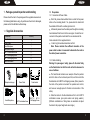
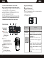
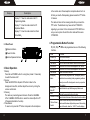
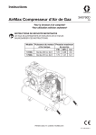
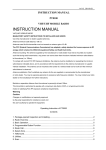
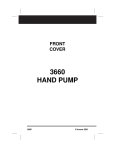
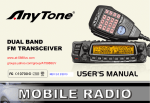
INSTRUCTION MANUAL
FM MOBILE TRANSCEIVER
PT8000
NOTE
INSTRUCTION MANUAL
PT8000
VHF/UHF MOBILE RADIO
MANDATORY SAFETY INSTRUCTIONS TO INSTAL-LERS AND USERS
Use Only manufacturer or dealer supplied antennas.
Antenna minimum safe distance: 108 cm.
Antennas used for this transmitter must not exceed an
antenna gain of 3 dB.
The FCC (Federal Communications Commission) has
adopted a safety standard for human exposure to RF
energy which is below the OSHA (Occupational Safety
and Health Act) limits.
Antenna mounting: The antenna supplied by the manu-facturer or radio dealer must not be mounted at a location
such that during radio transmission, any person can come
16
Closer than the above indicated minimum safe distance to the antenna (i.e. 108cm).
To comply with current FCC RF Exposure limitations,
the antenna must be installed at or exceeding the minim-um safe distance indicated above, and in accordance with
the requirements to the antenna manufacturer or supplier.
Vehicle installation: The antenna can be mounted at
the center of a vehicle metal roof or trunk lid if the minimum safe distance is observed.
Antenna substitution: Don't substitute any antenna for
the one supplied or recommended by the manufacturer
or radio dealer. You may be exposing person(s) toexcess-ive radio frequency radiation. You may contact your radio
dealer or the manufacturer for further instructions.
Warning
Maintain a separation distance from the antenna to
person(s) at least 108cm.
This transmitter is authorized to operate with a
maximum duty factor of 50%, in a typical push-to-talk
mode, for satisfying FCC RF exposure compliance
requirements.
Caution:
CONTENTS
Changes or modifications not expressly approved by the
party responsible for compliance could void the user's
authority to operate the equipment.
1. Package-opened Inspection and Installing......................................2
2. Radio Overview...............................................................................4
3. Basic Operation...............................................................................6
4. Programmable Button Function.......................................................7
5. Radio call................................................................................... .....8
6. Talk-around.....................................................................................9
7. Scan................................................................................................9
7.1 Start/End Scan Function...............................................................9
7.2 Nuisance Delete............................................................................9
8. Public Address..............................................................................10
9. Lone worker...................................................................................10
10. Emergency Alarm........................................................................10
11. Remote kill, stun, activate and revive................................. ........11
12. Wired Clone Mode.......................................................................12
13. Trouble Shooting Guide...............................................................13
14. Major Specifications....................................................................13
1
1 . Package-opened Inspection and Installing
Please check the host in the package and the supplied accessories in
the following table before using. Any articles are found lost or damaged,
please contact the distributor without delay.
1.1
Supplied Accessories
Quantity
Accessories
Fixed bracket
Power Cable
Hand Microphone
Microphone Hanger
M4*10 Combination Screw
M4*16 Self-tapping Screw
M5*16 Self-tapping Screw
Instruction Manual
2
1
1
1
1
4
2
4
1
Microphone Hanger
Power Cable
Fixed bracket
Hand Microphone
M4*10 Combination Screw
M5*16 / M4*16
Self-tapping Screw
1.2 Preparation
1.2.1 Connection of Power Cable
First of all, please check whether there is a hole for the power
cable on the insulating board. If no, please bore the board with
the suitable drill bit and fix a rubber grommet on it.
Afterwards, please have the cable pass through the insulating
board and lead from the car into the car engine. Connect the red
conductor to the positive terminal of the accumulator and the
black conductor to the negative terminal.
At last, ring the remained conductor and fix it.
Note: Please maintain the sufficient relaxation of the
power cable to make it convenient to dismantle the radio in
the state of power connection.
1.2.2 Radio Installing
Warning: For passengers' safety, please fix the radio firmly
on the fixed bracket so that the radio will not be loosened in
case of collision.
The fixed bracket is taken as an example. Draw the position
and drill a hole on the instrument panel first, and then install the
fixed bracket with 4 M5*16 self-tapping screws. (Note: please fix
the radio at the position convenient for operation and control,
and leave an enough space for fixation and connection of the
cable.)
Slide the radio into the fixed bracket and fix it with 4 M4*10
combination screws (plus plain washer and spring washer).
(Different combinations of fixing holes are selectable to adjust
the radio to the proper height and visual angle.)
3
Connect the antenna and the power cable to the radio.
Install the microphone hanger at the position easy to use, with
2 M4*16 self-tapping screws. (The microphone and its cable should
be fixed at the position not affecting safe driving.)
Connect the microphone to the microphone jack on the front
panel of the radio and put it on the hanger.
Note: When replacing the protective tube for the power cable,
please use the one of the same specification without fail. It is
not allowed to change it into the tube of higher capacity.
P1button (programmable button)
P2 button (programmable button)
P3button (programmable button)
PTT button (on the hand microphone)
Press the PTT button first, and then speak to the microphone to transmit the
voice to the other. Loosen to receive.
2.2 Display Screen
8
2 Radio Overview
8
2.1 Description of
External View
P1
power button
Press this button for
a long time (more than
1.5 seconds) to switch
The radio on/off.
LED indicator
The red indicator will light while
transmitting; the green indicator
Will light when it receives the carrier.
/
button (programmable button)
Display screen
For details, see Display .
Volume Control knob
To be used to adjust volume.
Microphone/Programming Interface
4
P2
Display
P3
Description
SCAN indicator
Scan indication: on when scan is enabled.
LOW indicator
Power level indication: on when in low power.
8
Indicates the current channel in normal use,
ranging from 1~8.
Indicates the current squelch level when
squelch selection is enabled,ranging from
0.~9.
Displays "b " when Public Address is enabled.
Displays "-" when the radio has no channel.
Displays "u " when the radio is in the remote
stun status.
Displays "h " when the radio is in the remote
kill status.
5
Display
Description
Displays "P " when the radio enters the PC
Programming Mode.
Displays "t " when the radio enters the PC
Adjustment Mode.
Displays "C " when the radio enters the Wired
Clone Mode
2.3 Rear Panel
Antenna Interface
Power Interface
External Speaker Interface
3. Basic Operation
1.Startup:
Press the red POWER button for a long time (at least 1.5 seconds)
to switch the radio on/off
2.Volume:
Press the MONITOR or Squelch Off button to listen to the
background noise first, and then adjust the volume by turning the
volume control knob.
3.Channel
The radio can provide 8 general channels. Press the CHANNEL
UP or CHANNEL DOWN button to select the channel.(Refre to P7
4 Programmable Button Function)
4.Transmission:
To send a call, press the PTT button and speak to the microphone
6
in th e normal voice. Please keep the microphone about 3 or 4 cm
far from your mouth. After speaking, please loosen the PTT button.
5. Receive:
The radio will return to the receiving state after you loosen the
PTT button. The distributor may have set the CTCSS/DCS
signaling in your radio. On the channels with CTCS S/DCS are
set, you can only hear the call from other radio with the same
CTCSS/DCS.
4. Programmable Button Function
P1 P2 P3
functions.
0. None
1.Channel Up
2.Channel Down
3.Talk-around
4.Call Button1
5.Call Button2
6.Lone worker
7.Emergency
Alarm
/
can be programmed as one of the following
No function
Select the next channel
Select the previous channel
Switch the radio mode between talk-around and repeater.
Sends the DTMF/2Tone code assigned to call 1 button.
Sends the DTMF/2Tone code assigned to call 2 button.
Enables Lone worker function
Press the button programmed as Emergency Alarm
to set alarm tone according to the programming software
or send your own ID or background voice to your partner
or the system.
Press this button to quit the Emergency Alarm mode.
8.Emergency
AlarmOff
9.Scan
Start/end the scanning function of system.
10.Nuisance Delete Press this button Nuisance Delete when the radio enables
11.Hi-Low Power
Switch
the scan function and stays at the noise channel.
Press to switch between high and low power of the sen ding
power of the radio, when the LOW is on the display,
7
the current sending power is low.
12.Monitor
momentary
13.Monitor
Hold to disable CTCSS/DCS signaling according to the
setting to resume normal operation.
Press to disable CTCSS/DCS signaling to receive signals
that cannot be heart in normal operation, press again to
resume normal operation.
14.Squelch off Hold to enable squelch and loosen to resume normal
momentary
operation.
15.Squelch off Press this button to open the squelch. Press it again
to return to the normal operation.
Press this button in the selective call state to quit such a state.
16.Lone worker After enabling the Lone worker, press this button to
reset
reset the Lone worker timer and the timing resumes.
17 .Public
Address
18.Squelch
Level
Selection
Start/end the public address function. Press this button and
the function will be activated. Press the PTT button and speak
to the micro-phone so that you can hear your voice through
the external speaker.Press this button once again and return
to the normal user mode.
Press this button to enter the Squelch Level Adjustment
Mode first, and then press the / button to adjust the level.
Press the PTT button to save the selected squelch level and
quit this mode. Press any other button to quit without saving.
5. Radio call
A.Press the button programmed as "call Button 1" or "call Button 2"
to send the preset code .
B.Press "PTT" and talk with the microphone in the normal voice.
Please keep the microphone about 3-4cm away from your lips.
When finish talking, release "PTT".
8
6. Talk-around
In the communication network, you can expand communication
range through the repeater, but when the mobile radio is out of the
communication range, you can connect with other radio in the
talk-around method.
Switch the talk-around or repeater mode through "Talk-around"
button.
7. Scan
The radio can be programmed to scan multiple channels to
receive signals.
7.1 Start/End Scan Function
Press the button programmed for "Scan" to enable scanning.
When the scan function is enabled, the "SCAN" indicator is on
and the channels being scanned are also displayed. Press the
"Scan" button again to disable scanning and the"SCAN"
indicator will be out.
7.2 Nuisance Delete
If a channel continuously generates noise or interference, press
the button to remove this channel from the scan list temporarily.
Note: the priority channel can't be removed and the last one in the
scan list, either.Quit the Scan mode and enter it again, the deleted
channel will be added to the scan list again.
9
8. Public Address
Press the button programmed for "Public Address", "b" will be
displayed.Press the PTT button, the voice from the MIC of the
radio will be directly sent to the external speakers through the
interface on the back.
Press the "Public Address" button again to disable the public
address function.
9. Lone worker
If Lone worker is set to be enabled, press the button "Lone
worker" to enable the Lone Worker Mode. Start the Lone worker
timer and when the preset Lone worker time is reached, the radio
will alarm, after the alarm time, the radio will enter the Emergency
Alarm Mode.
In the Lone worker Mode, press the "Lone worker" button again
to quit the Lone worker mode.
In the Lone worker Mode, press the button programmed for
"Lone worker reset" the specific button to select lone worker
reset mode or any button (any button to select lone worker
reset mode), the Lone worker timer will reset and start timing
again.
10. Emergency Alarm
Press the button programmed for "Emergency Alarm" (the time of
pressing must be longer than the de-bounce time of the emergency
alarm switch) to enter the Emergency Alarm mode. "E" will be
displayed. You can set alarm tone according to the programming
10
software or send Your own ID or background voice to your partner
or the system.
In the Emergency Alarm Mode, press the button "Emergency
Alarm Off" to quit the Emergency Alarm Mode and disable the
alarm tone or stop sending it and resume normal operation.
11. Remote kill , stun, acti vate and revive
If the radio received DTMF code programmed as remote stun,
the radio will enter the remote stun status, after replying
according to the setting, "u" will be displayed. The radio can only
receive signals and cannot send signals. If the radio received
DTMP code programmed as remote un-stun, the radio will quit
the remote stun status and enter normal operation.
If the radio received DTMF code programmed as remote kill, the
radio will enter the remote kill status, after replying according to
the setting, "h" will be displayed. The radio cannot send or receive
signals. If the radio received DTMP code is programmed as
revive, the radio will quit the remote kill status and enter normal
operation.
12. Wired Clone Mode
If the wired clone function is enabled, the radio will not quit after
entering the wired clone mode. To return to normal user mode,
the user needs to restart the machine.
The operating steps go as follows:
1. Press [P1] buttons for power-on until show "C" and enter the
11
clone mode. If the function is disabled, it will enter the user mode.
2. Connect the slave radio with the wired clone cable first, and then
turn on.
3. Press button [P2] on the master radio for starting clone. During
transmitting the data, the master radio lightens red, and the slave
radio lightens green and indicates "P". After the slave radio recei-ving all the data, the red light on the master radio is off, and the slave
radio restarts.
4. You can keep cloning according to step 3 above.
Problem
1
Power on
Failure
Solution
A. The power cable is not connected with the accumulator or the host
reliably. Please connect the power cable reliably.
B. The protective tube of power cable is burnt out. Please change it.
C. The power button is of poor contact. Please change th e silica
gel button or PCB button.
D. The rechargeable battery is out of power. Please recharge or
change a new one.
E. CPU is broken, Please change the IC.
A. Channel frequency beyond the range, reset channel data.
Phase lock loop
B. The crystal X1 of phase lock loop is broken. Please change it.
2 unlocked
C. The oscillator tube is broken. Please change it.
(Beeping)
D. The IC3 of phase lock loop is broken. Please change IC.
3
No talkback
4
No receiving
signal
12
A. The frequency is not right. Please reselect the channel
of the same frequency.
B. The CTCSS/DCS code is not the same. Please reset it.
C. It is out of the effective communication range.
Problem
Solution
B. The high-frequency amplifying tube Q18 is broken.
Please change it.
C. The squelch level is set to high Please reset the
squelch level.
D. The mixed tube Q19 is broken. Please change it.
E. The FM IC6 is broken. Please change IC.
5
6
13. Trouble Shooting Guide
NO.
NO.
The red transmission
A. Power module IC1 damaged, no power output,
Indicator lights but no
please change the module.
sound is heard.
B. MIC damaged, please change it.
The green receiving A. The speaker is broken. Please change it.
indicator lights but no B. The audio power amplifierIC7 is broken. Please
change IC.
sound is heard.
10 Major Specifications
14.
Frequency Range: 136MHz~174MHz 438MHz~490MHz
Channel Number: 8
Channel Spacing: 25kHz (wide band)/12.5kHz (narrow band)
Operating Voltage: 13.6V Dc 10%
Operating Temperature: -25 -+55
External Dimension: machine only: 150mm*53mm*130mm;
plus fixed bracket: 165mm*62mm*130mm
Weight: machine only: 1030g;
Plus fixed bracket: 1310g
A. The antenna is not in good contact. Please fasten the antenna
head.
13
DECLARATION
OF CONFORMITY
NOTE
0678
We, Kirisun Electronics(Shenzhen) Co., Ltd.
6/F, Bldg.H-2,East Industrial Zone Of Overseas
Chinese Town,Shenzhen 518053, China
Declare on our sole responsibility that this equipment complies with
the essential requirements of the Radio and Telecommunication
Terminal Equipment Directive,1999/5/EC,and that any applicable
Essential Test Suits measurement have been performed.
Description of equipment: FM MOBILE TRANSCEIVER
Model No.: PT8000
This compliances is based on conformity with the
following harmonised standards or documents:
(1). EN 60950
(2). EN 301 489-1/-5
(3). EN 300 086-1/-2
Shenzhen, 6 MAY 2008
WenLiang, Fu
Place and date of issue
General Manager
Signature
Kirisun Electronics Co., Ltd
14
15