1
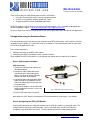
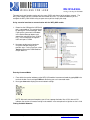
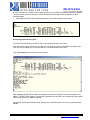
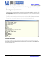
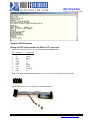
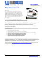
RN-131G-EVAL
rn-131g-eval-um.pdf 4/29/2009
WiFly GSX evaluation Kit
Overview
This document describes the hardware and software
setup for the Roving Networks WiFly GSX 802.11 b/g
module. In addition to the RN-131G-EVAL kit you will
need a Windows based computer with a USB port. You
may also need a null modem serial cable or USB to serial
cable, if you want to connect the WiFly GSX UART to
your computer.
The WiFly GSX module is mounted to a development
carrier board called the SURF board. This board has
status LEDS and connections for the programmer and UART interfaces.
The evaluation kit allows you to configure and program the WiFly GSX 802.11 b/g module using the command
interface, create connections and transfer data. The command interface is made up of simple ASCII
commands. A complete listing is available in the WiFly GSX User Manual (rn-131-um.pdf).
Evaluation Kit Description
The evaluation kit includes the following hardware required to connect to the WiFly GSX module though the
USB of your computer.
• SURF board with WiFly GSX module
•
•
Evaluation board – links your computer to the SURF board
10pin (2x5) 050” board to board cable – connects the SURF board to the evaluation board
•
•
USB cable – connects the SURF board to the host computer
Serial cable – connects the SURF board to a RS232 device
•
Header – for RS232 connections using the serial cable
In addition to the hardware in the WiFly GSX evaluation Kit you will need a x86 compatible computer with a
USB port running Windows XP or Vista. The WiFly GSX evaluation kit may work with other Windows versions
and operating systems. However this document only covers the Windows XP and Vista operation.
Before starting install the evaluation board drivers for the USB interface. These can be found on the Roving
Networks website at: http://www.rovingnetworks.com/bin/RN-USB-X-WINDOWS.exe
809 University Avenue • Los Gatos, CA 95032 • Tel (408) 395-6539 • [email protected]
RN-131G-EVAL
rn-131g-eval-um.pdf 4/29/2009
Surf Board Description
2 4 6 8 10
Evaluation Board Connector
1
2
3
4
5
10
8
6
4
2
6
7
8
9
10
Other Signals
9
7
5
3
1
WARNING: TTL signal levels
1 3 5 7 9
PIN
1
2
3
4
5
6
7
8
9
10
UART Interface
WARNING: Both RS232 and TTL
signal levels are on this interface
RX into the SuRF board
TX is from the SuRF board
PIN
1
2
3
4
5
6
7
8
9
10
Description Signal Level
TXDB
TTL
TX
RS232
RX
RS232
RTSB
TTL
GND
CTSB
TTL
RTS
RS232
CTS
RS232
VDC
9V DC
RXDB
TTL
Description
Sensor PWR
PIO7
Sensor-4
PIO8
Sensor-5
SPI_MISO
Sensor-6
SPI_CLK
Sensor-7
SPI MOSI
LED Indicators
1 2 3 4
5
Jumper Block
Jumper
1
2
3
4
5
Description
Do not use, removed
Adhoc mode
Config 1
Config 2
Config 3
Condition
Blue LED
Red LED
ON solid
Power On
Not Associated
Fast blink
Green LED
Connected over TCP
Rx/Tx data transfer
Slow blink
OFF
Yellow LED
Associated, No Internet
No Power
No IP address
IP address OK
Associated, Internet OK
Evaluation Board Description
RS232 Serial Port Interface
Use 10 pin to female DB9 cable
Not used for RN-131-EVAL
Evaluation Board Connector
Use 10 pin 0.5 pitch to cable
5
4
3
2
1
10
9
8
7
6
Programming Switch
Debug mode
Module reset
User Mode
Module wakeup
Jumper set for USB Operation
NOTE: The evaluation board should have the jumper set for
USB operation and the programming switch set to User Mode
809 University Avenue • Los Gatos, CA 95032 • Tel (408) 395-6539 • [email protected]
RN-131G-EVAL
rn-131g-eval-um.pdf 4/29/2009
There are three ways to setup and configure the WiFly GSX module
1. Using the Evaluation board with a terminal emulation program
2. Over the air using Adhoc networking mode with Telnet
3. Through the UART interface (Embedded applications)
NOTE: We suggest using TeraTerm as you terminal emulator program. This is available for download from
the Roving Networks website. http://www.rovingnetworks.com/support/teraterm.zip
Do not use HyperTerm with the Evaluation Board it has several bugs that make it unusable for this application.
Configuration using the Evaluation Board
The evaluation board physically connects your computer to the WiFly GSX module. With the drivers installed
the programmer will appear as a “USB Serial Port” on a COM port. The Evaluation board will have the green
LED on when plugged into the USB.
This is a two step process:
1. Making a connection to the WiFly GSX module
2. Configuring the WiFly GSX module to access the WiFi network
Once complete the WiFly GSX module is associated with the network and has acquired an IP address.
Step 1: Setting up the hardware
USB Connection:
1. Connect the USB extension cable to the
development board.
2. Connect the 10pin ribbon cable to the
evaluation board. When looking from
above, red side of the ribbon should be
towards the center of the module.
3. Connect the other end of the 10pin ribbon
cable to the WiFly GSX Module, the red
side of the ribbon cable should away from
the jumper block.
4. Verify that the jumper is set for USB mode,
and the programming switch is in the User
mode position.
5. Plug the USB cable into the computer.
Fig. 1 USB cable setup and jumper setting
Note: When the SuRF board is connected to the Evaluation board the 9 volt battery is not needed.
Step 2: Configuring the WiFly GSX Module
Configuration commands are made over the data channel when the module is in command mode. The
escape sequence $$$ enters command mode. Once in command mode, the WiFly GSX device is
configured using simple ASCI commands. To leave command and return to data mode type exit.
809 University Avenue • Los Gatos, CA 95032 • Tel (408) 395-6539 • [email protected]
RN-131G-EVAL
rn-131g-eval-um.pdf 4/29/2009
The most basic configuration requires only the name (SSID) and channel of the wireless network. The
WiFly GSX module can only associate with one network at a time. It is recommended that you first
configure the WiFly GSX module using an open access point to simplify the setup.
Using a terminal emulator to communication with the WiFly GSX module.
1. Determine the COM port the USB Serial
port is connected on. This can be found
by opening the “Device Manager” which
is part of the system tools in Windows.
In the Device Manager browse and
expand the selection for Ports (COM &
LPT) In the example to the right the
USB serial port is COM9
2. Next open up the terminal emulator
using the COM port found in the
previous step. If using TeraTerm, select
Serial and choose the COM Port from
the pull down list.
Entering Command Mode
1. From within the terminal window, put the WiFly GSX module into command mode by typing $$$ in the
terminal window. You should get CMD back confirming you are in command mode.
2. Next type show net to display the current network settings.
NOTE: After each command completes you will see a prompt that looks like <X.XX> where X.XX
indicates the version of firmware running on the module In the example to the right the version is 2.03
Finding Available Networks
809 University Avenue • Los Gatos, CA 95032 • Tel (408) 395-6539 • [email protected]
RN-131G-EVAL
rn-131g-eval-um.pdf 4/29/2009
Use the scan feature in the WiFly GSX module to find the name (SSID) and channel of available networks.
To start the scan you must have your terminal emulator connected and the WilFy module must be in
command mode.
• Type scan at the WiFly GSX command prompt for a list of WiFi networks within range
Associating with an access point
The red LED will be blinking if the WiFly GSX is not connected to and access point.
If the access point you’re connecting to is open you can simply use the join command to associate with it.
From the scan list above you can see that roving1 is an open network access point.
Type join roving1 to associate with an access point.
Upon rebooting the WiFly GSX module will attempt to associate with the WiFi network and acquire an IP
address. The WiFly GSX module is successfully configured if the red LED is off (associated) and the green
light is flashing slowly (IP address acquired).
You could also have specified the roving1 access point to connect to from the list by using the command
join # 1
809 University Avenue • Los Gatos, CA 95032 • Tel (408) 395-6539 • [email protected]
RN-131G-EVAL
rn-131g-eval-um.pdf 4/29/2009
If you know the name of the access point you want to connect to you can set it with out previously using
the scan command by setting the ssid with the set wlan ssid access_point_name and then using the
join command with no arguments.
Connecting to security enable networks
If the access point you are connecting is running security you will need to provide the security key. The
WiFly GSX module will determine the type of security automatically. You enter the security key with the
set wlan phrase key
You will also want to enter the name of the access point using the set wlan ssid access_point_name
Once you have set the security key you can confirm the setting by typing get wlan ssid
Saving your configuration
Your settings must be saved to the config file or they will not take effect on the next boot cycle. Save the
configuration to flash using the save command Now reboot the WiFly GSX module by typing reboot to see
that your changes take effect.
809 University Avenue • Los Gatos, CA 95032 • Tel (408) 395-6539 • [email protected]
RN-131G-EVAL
rn-131g-eval-um.pdf 4/29/2009
Using the RS232 Interface
Warning the UART Interface contains both RS232 and TTL signal levels
Applying greater than 3.3VDC to pins 1, 4, 6 or 10 can permanently damage the module!
PIN
1
2
3
4
5
6
7
8
9
10
Description
TXD
TX
RX
RTD
GND
CTSD
RTS
CTS
VDC
RXD
Signal Level
TTL
RS232
RS232
TTL
TTL
RS232
RS232
5 to 9V DC
TTL
Soldier in the partially populated header (pictured below) to connect the 10 pin connector ribbon cable to the module
With the header installed the pin 10 to DB9 ribbon cable is installed as such
809 University Avenue • Los Gatos, CA 95032 • Tel (408) 395-6539 • [email protected]
RN-131G-EVAL
rn-131g-eval-um.pdf 4/29/2009
Using Adhoc mode
The Surf Board is put into Adhoc mode by putting on jumper 2. Jumper 2 is actually the first available jumper since jumper 1 pins have
been clipped to avoid accidental shorting to VDC.
With the Surf Board in adhoc mode connect the 9 volt battery. The SuRF board will flash the red, yellow and green LEDs in sequence
when the module is in adhoc mode.
The WiFly module creates the following adhoc network with
SSID:
WiFly-GSX
IP address:
169.254.1.1
Connect to the WiFly-GSX network by go into the “Control Panel / Networking and Sharing / Networking and Sharing Center” dialog in
Vista or “Control Panel / Network Connections” dialog in Windows XP. From here, view available networks and select the WiFly-GSX
network. Once successfully associated the red LED will blink fast and the yellow LED will go off. The green LED remains blinking to
indicate there is an IP address but no active connection.
Note: Vista may take one or two minutes allocating IP address for your computer (Auto IP). To work around this you can assign a
static IP address.
Once you have associated with the WiFly-GSX network you will be able to ping the WiFly module at the IP address 169.254.1.1 or
open a telnet window using port 2000. From telnet you can send data to the WiFly UART or enter command mode to configure the
module. For example, it is useful to use adhoc mode to set and save the SSID and security key for enterprise networking without
using the development board or UART connection.
Note: The module can not be in Adhoc and Enterpise network mode simultaneously.
809 University Avenue • Los Gatos, CA 95032 • Tel (408) 395-6539 • [email protected]
RN-131G-EVAL
rn-131g-eval-um.pdf 4/29/2009
Trouble Shooting
WiFly GSX module red LED remains on after setting SSID and channel
The WiFly GSX module can not connect to the networks. Possible problems include, not
saving the configuration before rebooting, enter command mode and verify settings. Incorrect
or missing WEP/WPA keys, confirm access point is either open (no security) or you have the
right authentication level set and the correct pass phrase or key.
WiFly GSX Module red LED is off, but green LED is flash quickly
The WiFy module is associated with the network but was unable to get an IP address. Check
the DHCP is ON in WiFly GSX configuration. If using a static IP address make sure the subnet mask and the gateway IP addresses are set correctly using the get ip command
Copyright © 2009 Roving Networks. All rights reserved.
The Bluetooth trademark and logo are registered trademarks of Bluetooth SIG, Inc. All other trademarks are
property of their respective owners.
Roving Networks reserves the right to make corrections, modifications, and other changes to its products,
documentation and services at any time. Customers should obtain the latest relevant information before
placing orders and should verify that such information is current and complete.
Roving Networks assumes no liability for applications assistance or customer’s product design. Customers are
responsible for their products and applications which use Roving Networks components. To minimize
customer product risks, customers should provide adequate design and operating safeguards.
Roving Networks products are not authorized for use in safety-critical applications (such as life support) where
a failure of the Roving Networks product would reasonably be expected to cause severe personal injury or
death, unless officers of the parties have executed an agreement specifically governing such use.
809 University Avenue • Los Gatos, CA 95032 • Tel (408) 395-6539 • [email protected]