1
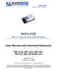
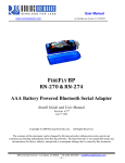
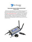
RN-WIFLY-EVAL-UM WiFly Evaluation Kit © 2011 Roving Networks. All rights reserved. RN-WIFLY-EVAL-UM-1.0 Version 1.0 11/8/2011 USER MANUAL RN -W IFLY- E VAL-U M- 1.0 OVERVIEW This document describes the hardware and software setup for Roving Networks evaluation kits, which contain the hardware you need to evaluate the RN-171 or RN-131 WiFly 802.11 b/g modules. The RN-171 and RN-131 WiFly modules are mounted to evaluation boards. Each board contains status LEDs, connections for the programmer and UART interfaces, a voltage regulator, and easy access to GPIO pins. You can use the evaluation kits to configure and program the WiFly module using the command interface, create connections, and transfer data. The command interface is made up of simple ASCII commands. See “Resources & Related Documents” on page 15 for information on available documentation. Evaluation Kit Description The evaluation kits include the hardware required to connect the evaluation board to your computer. See Table 1 for information on which hardware is provided with each kit. Additionally, Appendix A provides photographs and detailed information on each kit’s contents. To evaluate the module on the evaluation board, you need a computer with a USB port running the Microsoft Windows or Mac OS-X operating system. NOTE: Before beginning your evaluation, you must install the drivers for the USB-to-serial cable. You can download the drivers (as well as other tools and utilities) from the Roving Networks website at http://www.rovingnetworks.com/support.php. Table 1. Evaluation Kit Hardware Hardware Description RN-131G-EVAL RN-134-K RN-174-K Evaluation board Contains the WiFly module and connectors. For RN-131 module For RN-131 module For RN-171 module USB-to-serial cable Links your computer to the evaluation board. Contains the Prolific chipset. ✔ ✔ ✔ Null modem Connects the 10-pin serial cable to the USB-toserial cable. ✔ ✔ ✔ 10-pin serial cable Connects from the board’s RS-232 header to a DB9 connector. ✔ ✔ ✔ 9-V battery clip Provides power to the evaluation board (requires a battery). ✔ ✔ ✔ Antenna cable U.FL and reverse SMA connectors. ✔ 4” dipole antenna Reverse SMA connector. ✔ Figure 1 shows the RN-134 evaluation board and pin information. Table 2 describes the LED indicators. www.rovingnetworks.com 2 RN -W IFLY- E VAL-U M- 1.0 Figure 1. RN-134 Evaluation Board Jumper Block (J2) LED Indicators RS-232 Interface (J1) UART Interface (J3) Sensors (J4) RS-232 Interface (J1) 10 9 8 7 6 5 4 3 2 1 Power (J5) UART Interface (J3) 1 2 3 4 5 6 7 8 9 10 11 12 13 RX - input to evaluation board TX - output from evaluation board Pin Description 1 No connect 2 RX 3 TX 4 No connect 5 GND 6 No connect 7 RTS 8 CTS 9 5 to 12 VDC input 10 No connect Power (J5) 2 1 1 2 3 4 5 6 7 8 RX - input to evaluation board TX - output from evaluation board Pin Description 1 3.3 VDC output 2 GND 3 RXDB 4 TXDB 5 RSTB 6 CTSB 7 PIO4 8 PIO5 9 PIO6 10 PIO7 Pin Description 11 PIO8 1 5 to 12 VDC 12 Reset 2 GND NOTE: The labels on the board for RX and TX are incorrect. www.rovingnetworks.com Sensors (J4) Pin Description 1 Sensor PWR 2 Resistor network to Sensor 4 3 Resistor network to Sensor 4 4 Sensor 7 5 Sensor 4 6 Sensor 5 7 Sensor 6 8 GND WARNING: Sensors must not have more than 1.2-V DC. Otherwise, the module may be permanently damaged. Jumper Block (J2) 4 3 2 1 Pins Description 1 Ad hoc mode and factory reset 2 Config 1 3 Config 2 4 Config 3 3 RN -W IFLY- E VAL-U M- 1.0 Table 2. RN-134 Evaluation Board LED Indicators Condition Blue LED Red LED Yellow LED Green LED On solid Power On -‐ -‐ Connected over TCP Fast blink -‐ Not associated Rx/Tx data transfer No IP address Slow blink -‐ Associated, no Internet -‐ IP address OK Off No Power Associated, Internet OK -‐ - Figure 2 shows the RN-174 evaluation board and pin information. Table 3 describes the LED indicators. www.rovingnetworks.com 4 RN -W IFLY- E VAL-U M- 1.0 Figure 2. RN-174 Evaluation Board (Part 1 of 2) Power Select Jumper (J4) LED Indicators Power (J7) Pull Up/ Down (J2) Factory Reset/ Ad Hoc Mode (J6) PCB Trace Antenna ISP Connector (J5) GPIO Interface TTL Signals (J8) Sensor Interface (J1) RS-232 Interface (J3) GPIO Interface TTL Signals (J8) 5 4 3 2 1 10 9 8 7 6 RS-232 Interface (J3) 1 2 3 4 5 6 7 8 9 10 11 12 13 RX - input to evaluation board TX - output from evaluation board Sensors (J1) 9 8 7 6 5 4 3 2 1 Pin Description 1 Sensor PWR 2 Sensor 4 (3.3-V tolerant) 3 Sensor 5 (3.3-V tolerant) 4 Sensor 7 (1.2 V only) 5 Sensor 5 (1.2 V only) 6 Sensor 4 (1.2 V only) 7 Sensor 6 (1.2 V only) 8 Sensor 3 (1.2 V only) 9 GND Pin Description 1 No connect 2 RS-232 TX 3 RS-232 RX 4 No connect 5 GND 6 No connect 7 RS-232 RTS Pin Description 8 RS-232 CTS 1 3.3 VDD 9 4 to 16 VDC input 2 GND 10 No connect 3 UART RX 4 UART TX 5 GPIO4 6 GPIO5 7 GPIO6 Pin Description 8 GPIO7 1 5 to 12 VDC 9 GPIO8 2 GND 10 GPIO9 11 UART CTS Pull Up/Down (J2) 12 UART RTS 3 2 1 13 RESET Power Select Jumper (J4) High-Voltage Mode (Default). The board is powered by a source up to 16 V DC. Low-Voltage Mode. The board is powered by 2.0- to 3.3-V DC only. External Power Mode. Used when powering the board with regulated 3.3-V DC power. www.rovingnetworks.com RX - input to evaluation board TX - output from evaluation board WARNING: Voltage on pins marked 1.2 V Only should not exceed 1.2 V or permanent damage will occur. Power (J7) 2 1 Ad Hoc Mode/Factory Reset (J6) 5 RN -W IFLY- E VAL-U M- 1.0 Figure 2. RN-174 Evaluation Board (Part 2 of 2) ISP Connector (J5) 1 3 5 7 9 11 13 15 2 4 6 8 10 12 14 16 Pin Description 1 GND 2 3.3 VDD 3 DMA UART TX 4 UART RX 5 FORCE AWAKE 6 RESET 7 DMA UART RX 8 UART TX 9 3.3 VDD 10 GND 11 GPIO9 12 GPIO4 13 GPIO5 14 GPIO6 15 GPIO8 16 Not Used Table 3. RN-174 Evaluation Board LED Indicators Condition Blue LED Red LED Yellow LED Green LED On solid Not used -‐ -‐ Connected over TCP Fast blink Not used Not associated Rx/Tx data transfer No IP address Slow blink Not used Associated, no Internet -‐ IP address OK Off Not used Associated, Internet OK -‐ - www.rovingnetworks.com 6 RN -W IFLY- E VAL-U M- 1.0 HARDWARE SETUP To set up the evaluation kit hardware, perform the following steps: 1. Provide power to the board by soldering the provided 9-battery clip wire to the board (J7) and attaching a 9-V battery to the clip. 2. Connect the 10-pin serial cable to the evaluation board (J3). When looking at the top of the board, the cable should extend away from the board. NOTE: If your computer has a DB9 connector, you can connect the 10-pin serial cable directly to it to complete setting up the hardware. The COM port in this case is COM1. 3. Connect the USB-to-serial cable to a USB port on your computer. Windows should automatically install the drivers for the cable. If it does not, download and install the Prolific drivers from the Support page on the Roving Networks website at http://www.rovingnetworks.com/support.php. Note the COM port to which you have attached the cable. 4. Connect the USB-to-serial cable to the 10-pin serial cable using the null modem. Figure 3 shows the completed hardware setup for the RN-134 and RN-174 evaluation boards. NOTE: By default, the WiFly module uses either the on-board chip antenna (RN-131G-EVAL and RN-134) or the PCB trace antenna (RN-174). If an antenna is included in your kit, you do not need to install it for the evaluation described in this document. www.rovingnetworks.com 7 RN -W IFLY- E VAL-U M- 1.0 Figure 3. Hardware Setup RN-134 Evaluation Board Hardware Setup RN-174 Evaluation Board Hardware Setup NOTE: Refer to Power (J5) in Figure 1 (RN-134) and Power (J7) in Figure 2 (RN-174) for information on where to solder the wires. www.rovingnetworks.com 8 RN -W IFLY- E VAL-U M- 1.0 CONFIGURATION The WiFly module operates in two modes: data mode (default) and command mode. While in data mode, the WiFly module is essentially a data pipe. When the module receives data over Wi-Fi, it strips the TCP/IP headers and trailers and passes the user data to the UART. When data is written to the UART, the module constructs the TCP/IP packet and sends it out over Wi-Fi. Thus, the entire process of sending/receiving data to the host is transparent to the end microprocessor. See Figure 4. Figure 4. Data & Command Modes Host Wi-Fi Wi-F Fi User Data B A UART WiFly Module Wi-Fi Interface $$$ A B $$$ Command Mode By default, the module is in data mode. Sending the escape sequence $$$ causes the module to enter command mode. Once in command mode, you can configure the WiFly device using simple ASCII commands. To exit command mode and return to data mode, type exit <cr>. Basic configuration only requires the wireless network access point’s name (SSID) and authentication password. The WiFly module can only associate with one network at a time. Roving Networks recommends that you begin your evaluation by configuring the WiFly module using an open access point to simplify the setup. There are two ways to configure the WiFly module: • Over the UART, which is connected to a computer or microprocessor • Via Wi-Fi using ad hoc networking You need a terminal emulator to complete the setup. NOTE: Roving Networks suggests using either the TeraTerm (Windows OS) or CoolTerm (Mac OS-X) terminal emulator program. Configuration Using the RS-232 Serial Interface The USB-to-serial cable allows your computer to communicate with the WiFly module on your evaluation board. The following instructions describe how to use a terminal emulator to go into configuration mode, send commands to find networks, associate with an access point, and save your configuration. www.rovingnetworks.com 9 RN -W IFLY- E VAL-U M- 1.0 Configure the Module Using a Terminal Emulator To communicate with the module using a terminal emulator, perform the following steps: 1. Determine the COM port that was assigned to the USB-to-serial cable. If you do not know the COM port number, you can find it using the Windows Device Manager, which is in the system tools. In the Device Manager, browse and expand the selection for Ports (COM & LPT). In the example shown in Figure 5, the USB serial port is COM9. For OS-X, if you are using CoolTerm, you can view and select the port from within the application. 2. Open your terminal emulation program. 3. Specify the COM port. If you are using TeraTerm, select Serial and choose the COM port number from the Port dropdown list box. NOTE: The default serial port setting for the WiFly module is 9600 baud, 8 bits, no parity, and 1 stop bit. Figure 5. Finding the COM Port Number in Windows Example COM Port Setting Enter Command Mode To enter command mode, perform the following steps in the terminal emulator: 1. Type $$$. You must type $$$ together quickly with no additional characters before or after them. The module replies with CMD to indicate it is in command mode. 2. Type show net <cr> to display the current network settings. www.rovingnetworks.com 10 RN -W IFLY- E VAL-U M- 1.0 NOTE: When a command completes, the terminal displays a prompt in the format <X.XX> where X.XX indicates the module’s firmware version. In Figure 6, the version is 2.28. Figure 6. Show Current Network Settings To issue commands to the module, you send a keyword followed by optional parameters. Commands are case sensitive, and you cannot use spaces in parameters. Use a $ to indicate a space, e.g., MY NETWORK should be written as MY$NETWORK. Additionally, you can use shorthand for the parameters. For example, the following commands are equivalent: • set uart baudrate 115200 • set uart b 115200 • set u b 15200 NOTE: You cannot use shorthand for command keywords. For example, s uart baudrate 115200 is illegal. The WiFly module supports a variety of command keywords. The Advanced User Manual, which is available on the Support page of the Roving Networks website, provides a complete command reference. For evaluation purposes, you may view the current settings using the get command; get everything shows all parameters. Table 4 shows additional parameters for the set and get commands. Table 4. Basic set & get Parameters Parameter Function adhoc Controls the ad hoc parameters. broadcast Controls the broadcast hello/heartbeat UDP message. comm Communication and data transfer, matching characters. dns DNS host and domain. ftp FTP host address and login information. ip IP settings. option Optional and infrequently used parameters. sys System settings, such as sleep and wake timers. time Realtime clock settings. uart Serial port settings, such as baud rate and parity. wlan Wireless interface, such as SSID, channel, and security options. www.rovingnetworks.com 11 RN -W IFLY- E VAL-U M- 1.0 Find Available Networks Once you are in command mode, you can instruct the WiFly module to search for available networks. Type scan <cr> in the terminal emulator to view a list of Wi-Fi networks within range. See Figure 7. Figure 7. Scan for Networks Associate with an Access Point You use the join keyword to associate with an open access point. As shown in the scan list, roving1 is an open access point. To associate with an access point, type the following commands (refer back to Figure 7): join roving1 or join # 1 To disconnect from a network, type leave <cr>. The red LED blinks quickly when the WiFly module is not associated with an access point. If you want the module to associate with a network automatically upon booting (i.e., persistent configuration), use the set wlan command with the SSID name. For example, type: set wlan ssid roving1 save reboot When the module wakes or power cycles, the module attempts to associate with the network roving1. To associate with a secure network you must also include the network password. The WiFly module determines the security type automatically. In this case, type: set wlan ssid roving1 set wlan pass rubygirl save reboot www.rovingnetworks.com 12 RN -W IFLY- E VAL-U M- 1.0 See Figure 8. You can confirm the security settings by typing get wlan <cr>. Figure 8. Connect to a Secure Network Configuration Using Ad Hoc Mode You can configure the WiFly module over the air via an ad hoc network. Ad hoc networks are useful for point-to-point communication. In ad hoc mode, the WiFly appears as an access point with which other Wi-Fi devices can associate. You can turn on ad hoc mode using hardware or software configuration. NOTE: the WiFly module only supports the OPEN mode for ad hoc networks. Enable Ad Hoc Mode via Hardware To enable ad hoc mode using hardware, set GPIO9 high (3.3 V) at power up. For the RN-134 board, GPIO9 is on pin 1 on the jumper block (J2). For the RN-174 board, GPIO9 is on the J6 connector. Upon power up with GPIO9 high, the WiFly module creates an ad hoc network with the following settings: SSID: WiFly-GSX-XX, where XX is the final two bytes of the device’s MAC address IP address: 169.254.1.1 Enable Ad Hoc Mode via Software To enable ad hoc mode in software, you use the set wlan command with the join, ssid, and chan parameters. For example, type the following commands in command mode: set wlan join 4 set wlan ssid my_adhoc_network set wlan chan 1 www.rovingnetworks.com 13 RN -W IFLY- E VAL-U M- 1.0 Set the WiFly module’s IP address and netmask. Because automatic IP assignment fixes the first two bytes of the IP address, use 255.255.0.0 as the netmask so that other devices connecting to the module can be reached. You can also set the netmask to a smaller subnet if the other device’s IP addresses begin statically at the same subnet as the ad hoc device. set ip address 169.254.1.1 set ip netmask 255.255.0.0 Turn off DHCP so that the module does not attempt to obtain an IP address from another device. set ip dhcp 0 Save your configuration and reboot. The module will be in ad hoc mode. See Figure 9. Figure 9. Enable Ad Hoc Network Mode Associate with an Ad Hoc Network The WiFly module can associate with an ad hoc network created by another device. Type the commands: set wlan ssid my_adhoc_network save reboot To associate with an ad hoc network without saving the changes to the module’s flash memory, use the join command, e.g., join my_adhoc_network <cr>. If DHCP is enabled, the WiFly device obtains an IP address automatically when it associates with the ad hoc network. By definition, auto IP sets the first two bytes of the subnet to 169.254.xxx.xxx. The WiFly device requires 2 to 3 seconds to resolve the IP address. To set the IP address statically, disable DHCP and explicitly assign the IP address: set ip dhcp 0 set ip address 169.254.1.2 www.rovingnetworks.com 14 RN -W IFLY- E VAL-U M- 1.0 You can confirm that the device has properly associated with the ad hoc network using the ping keyword: ping 169.254.1.1 10 Associate with the WiFly Module over an Ad Hoc Network from a Computer You can associate with the ad hoc network from a computer by specifying the network name (and password, if required) in the operating system. For example, choose Control Panel > Networking and Sharing > Networking and Sharing Center (Windows Vista) or Control Panel > Network Connections (Windows XP). You can then view available networks and select the name of the WiFly ad hoc network. NOTE: Once associated with the ad hoc network, Windows Vista may require a few minutes to allocate an IP address. To work around this issue, assign a static IP address under Network Settings > TCP/IP > Properties. Once your computer is associated with the ad hoc network, you can use the WiFly module’s IP address to open a connection or connect using telnet as you would with an enterprise connection. NOTE: The WiFly module does not support ad hoc and infrastructure network modes simultaneously. Once you have associated with the other network, you can telnet into the WiFly module to configure it. Open the telnet connection using port 2000. NEXT STEPS Once you have set up the evaluation kit hardware and have gone through your initial evaluation using the instructions in this user guide, refer to the labs in the WiFly Training Presentation to get started developing applications. RESOURCES & RELATED DOCUMENTS For more information, refer to the following sources, which are available on the Support page on the Roving Networks website at http://www.rovingnetworks.com/support.php: • RN-171 Data Sheet • RN-131 Data Sheet • Advanced User Manual • WiFly Training Presentation • Drivers, tools, and utilities www.rovingnetworks.com 15 RN -W IFLY- E VAL-U M- 1.0 APPENDIX A – EVALUATION KIT CONTENTS & ORDER DETAILS Table 5 shows the contents of the RN-131G-EVAL, RN-134-K, and RN-174-K evaluation kits. Table 5. Evaluation Kit Contents Kit Photo Contents RN-131G-EVAL Kit • • • • • • • RN-134: Evaluation board for RN-131 module RN-USB-SERIAL: USB-to-serial cable with male DB-9 connector RN-UFL-SMA-6: U.Fl-to-SMA connector cable RN-SMA-4-RP: 4" reverse antenna with SMA connector 10-way ribbon cable with male DB-9 termination Null modem Battery clip RN-134-K Kit • • • • • RN-134: Evaluation board for RN-131 module RN-USB-SERIAL: USB-to-serial cable with male DB-9 connector 10 way ribbon cable with male DB-9 termination Null modem Battery clip RN-174-K Kit • • • • • RN-174: Evaluation board for RN-171 module RN-USB-SERIAL: USB-to-serial cable with male DB-9 connector 10-way ribbon cable with male DB-9 termination Null modem Battery clip www.rovingnetworks.com 16 RN -W IFLY- E VAL-U M- 1.0 NOTES www.rovingnetworks.com 17 RN -W IFLY- E VAL-U M- 1.0 Copyright © 2011 Roving Networks. All rights reserved. Roving Networks is a registered trademark of Roving Networks. Apple Inc., iPhone, iPad, iTunes, Made for iPhone are registered trademarks of Apple Computer. Roving Networks reserves the right to make corrections, modifications, and other changes to its products, documentation and services at any time. Customers should obtain the latest relevant information before placing orders and should verify that such information is current and complete. Roving Networks, Inc. 102 Cooper Court Los Gatos, CA 95032 +1 (408) 395-5300 www.rovingnetworks.com www.rovingnetworks.com Roving Networks assumes no liability for applications assistance or customer’s product design. Customers are responsible for their products and applications which use Roving Networks components. To minimize customer product risks, customers should provide adequate design and operating safeguards. Roving Networks products are not authorized for use in safety-critical applications (such as life support) where a failure of the Roving Networks product would reasonably be expected to cause severe personal injury or death, unless officers of the parties have executed an agreement specifically governing such use. 18