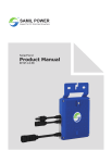
1
TM
SAMIL POWER
Expert for PV Grid-tied Inverters
SolarLake Grid Connected Inverter
Product Manual
SP–SL–V5.3–EN
English
Copyright Declaration
The copyright of this manual belongs to Samil Power Co., Ltd. Any Corporation or individual should not
plagiarize, partially copy or fully copy this document (including software). This document should not be
reproduced or distributed in any form or means. All rights reserved.
Samil Power reserves the right of final interpretation. This manual is subject to change according to user or
customer feedback, hence please check website www.samilpower.com for the latest version.
01
02
Contents
1
2
3
4
Basic safety information
7
1.1
Preface
7
1.2
General information
7
1.3
Safety instruction
7
1.4
Pre installation checks
8
1.5
Transport
8
1.6
Electric connection
8
1.7
Operation
8
1.8
Maintenance and repair
9
1.9
EMC / noise level of inverter
9
Product description
10
2.1
Function
10
2.2
Electrical block diagram
10
2.3
Dimension
11
2.4
Product label
11
Protection devices
12
3.1
Auto shut down
12
3.2
Additional protection devices
12
Installation
12
4.1
Packing list
12
4.2
Safety instruction
13
4.3
Precaution
14
4.4
Preparation
15
4.5
Installation Steps
15
4.6
Connecting PV array to inveter
16
4.7
5
6
4.6.1
Notes
16
4.6.2
PV array connection types
16
4.6.3
Assembly steps of DC connectors
17
4.6.4
Assembly steps of AC connector
19
4.6.5
Grounding
20
Safety inspection before commissioning
20
Commissioning of inverter
21
5.1
Start inverter
21
5.2
Check country setting and PV array connection type
21
5.2.1
Checking Country setting
21
5.2.2
Programming PV array connection type
23
Operation
24
6.1
Control and display panel
24
6.2
LCD Settings
25
6.2.1
Standard interface
25
6.2.2
Main menu
25
6.2.3
Instantaneous data
25
6.2.4
Historical data
25
6.2.5
Event list
26
6.2.6
Restore factory settings
26
6.3
LCD function
30
6.4
CEI 0-21
30
6.5
BDEW
37
03
7
8
9
Communication and monitoring
43
7.1
Communication interface
43
7.2
Communication mode
43
7.2.1
RS232 communication for single inverter
43
7.2.2
RS485 communication
43
7.2.3
Ethernet communication
44
Troubleshooting
45
8.1
Troubleshooting
45
8.2
Daily maintenance
50
Decommissioning
50
9.1
Decommissioning steps
50
9.2
Package
50
9.3
Storage
50
9.4
Disposal
50
10 Technical data
Input (DC)
51
10.2
Output (AC)
51
10.3
Efficiency, Safety and Protection
52
10.4
General data
52
11 Manufacturer’s warranty and liability clauses
04
51
10.1
53
● Notes on this Manual
This manual is an integral part of the inverter. Please read the manual carefully before installation, operation
or maintenance. Keep this product manual for future reference. Please note that all pictures are edited by
Samil Power.
● Scope of Validity
This product manual describes the assembly, installation, commissioning, and maintenance of the following
Samil Power SolarLake Series inverters.
SolarLake 10000TL
SolarLake 12000TL
SolarLake 15000TL
SolarLake 17000TL
Keep this manual where it shall be accessible at all times.
● Target Group
This manual is for qualified persons installing and operating the inverters. The tasks described in this manual
must only be performed by qualified persons.
● Symbols Used
This manual provides safety and operation information and uses symbols in order to ensure personal
and property security and efficient operation of inverters. User must understand and observe instructions
in the manual to avoid personal injury and property loss. Please read and understand the following
symbols which are used in this manual.
Danger
Danger indicates a hazardous situation which. if not avoided, will result in death
or serious injury.
Warning
Warning indicates a hazardous situation which, if not avoided, could result in
death or serious injury.
Caution
Caution indicates a hazardous situation, if not avoided, could result in minor or
moderate injury.
Note
Note provides tips that are valuable for the optimal operation of the product.
Attention
Attention indicates potential risks, if ignored prevent may lead to equipment
malfunction or damage.
05
● Symbols on the Inverter
These are some symbols which are related to safety and security. Please read and fully understand
these symbols before installing the equipment.
Symbol
Explaination
30 min
There will be residual voltage in the inverter! Ensure that AC and DC
sides are not charged before installation or maintenance. Capacitors
in the inverter are likely to be charged, hence it is necessary to wait
for about 30 minutes before opening the inverter cover.
Be careful of high voltage.
Be careful of high temperature.
Symbol of European Community
Inverter meets CE safety certification standard.
In the event of any property destruction or personal injury due to failure to follow instructions in this
manual, Samil Power Co., Ltd does not take any responsibility for the same.
06
Basic safety information
1 Basic safety information
Note!
If you have any questions or concerns when reading this manual, please contact Samil
Power Co., Ltd.
1.1 Preface
Installation of SolarLake inverter must completely meet with national and local grid connection standards
and regulations.
● Please contact Samil Power authorized repair center if you have any maintenance or repair services for
the inverter. Your dealer should be able to provide details of your nearest authorized service centre.
Please do not attempt any maintenance yourself as it may cause property destruction and personal injury.
● Read and understand the instruction in this manual and familiarize with the relevant safety symbols before
installing or maintaining the equipment.
● National and State regulations may require prior approval before connecting on site power generation systems
to the local grid.
● Before installing or maintaining the inverter, PV array and grid supply must be disconnected to avoid injury.
1.2 General information
When the inverter is operating, some of the parts will be electrically charged and/or very hot. Property
destruction and personal injury can be caused if the inverter is installed or operated wrongly. The inverter
must be installed and maintained by qualified and trained engineers and must meet all regulations in the
Country.
Samil Power Co., Ltd does not take any responsibility for the property destruction and/or personal injury
because of incorrect use of inverters.
1.3 Safety instruction
Danger!
Danger to life due to high voltages in the inverter!
• All work on the inverter must be carried out by qualified person only;
• The appliance is not to be used by children or persons with reduced physical,
sensory or mental capabilities, or lack of experience and knowledge.
• Children should be supervised to ensure that they do not play with the appliance.
Caution!
Danger of burn injuries due to hot parts!
During inverter operation, should only touch the display and keys on the inverter.
Attention!
PV array should be connected to the ground in accordance with requirements
of local regulations
To protect system and avoid personnel injury, Samil Power suggests that PV array
frame and inverter should be properly grounded.
Warning!
Ensure that the input DC voltage is less than the Max.DC voltage rating of the
inverter under all operating conditions. Over voltage may cause permanent damage
to the inverter or lead to other losses, which are not covered by product warranty.
07
Basic safety information
Warning!
Disconnect both AC and DC power from the inverter before opening the inverter. All
maintenance work should only be carried out by qualified and trained Electrical
Engineers.
1.4 Pre installation checks
Mount the inverter vertically on appropriate load bearing areas like walls or frames. Ensure that the location
selected for installing inverter has good air circulation, adequate room for undertaking maintenance tasks
and proper fire exit facilities.
1.5 Transport
All SolarLake inverters leaving the factory are thoroughly are tested and inspected to ensure the high
quality of our products. Our products are packed safely to ensure that these are not damage during
transportation. However, damage in transport do happen and in such cases the responsibility lies with the
transportation company.
While taking delivery of the goods, please check inverter and if packing or transit damages are found,
please inform transportation company immediately. If you need assistance please contact your supplier
or Samil Power Co. Ltd.
If the inverter is to be returned the original packing materials or suitable alternative must be used to avoid
damage during transport.
1.6 Electric connection
Please comply with all the local electrical regulations to prevent accident and damage.
Danger!
Before making electrical connection, use opaque materials to cover the PV modules
or disconnect PV panel DC switch. Beware that PV modules produce dangerously
high voltages when exposed to sun.
Warning!
All installation work must be done only professional electrical engineer.
● Must be trained;
● Read and understand the User manual.
Attention!
If necessary obtain prior permission from the local energy supplier before connecting
the inverter to the grid.
1.7 Operation
Attention!
Some internal components will be very hot when the inverter is working. Please
wear protective gloves.
08
Basic safety information
Danger!
Touching the power grid or electrical terminals may lead to electric shock or fire and
may lead to death or serious injury.
● Don’t touch the terminals or conductor When live.
1.8 Maintenance and repair
Danger!
Disconnect the PV array and electricity grid before undertaking any work on the
inverter.
Wait about 5 minutes after turning off AC and DC switches to discharge capacitors
before opening the inverter cover.
Attention!
In case of any problem with the inverter, please contact your local authorized
service center.
Attention!
There are no user serviceable parts inside the inverters, hence do not open the inverter.
Samil Power Co., Ltd does not take any responsibility if this advice is ignored.
1.9 EMC / noise level of inverter
Electromagnetic compatibility (EMC) ensures that electrical equipment function without electromagnetically
interfering with other electrical equipment as well as not imposing unacceptable effect upon the environment.
EMC represents the quality characters of electrical equipment.
● The inherent noise-immune character: immunity to internal electrical noise.
● External noise immunity: immunity to electromagnetic noise in external system.
● Noise emission level: influence of electromagnetic emission upon environment.
Warning!
Electromagnetic radiation from inverter may be harmful to health.
• Please do not stay close to the inverter for long periods when operating.
Keep minimum distance of 20 cm.
09
Product description
2 Product description
2.1 Function
The SolarLake Series PV inverters converts the DC power of a PV generator to grid compatible AC power
and feed it into the public grid.
PV Modules
Grid-tied Inverter
Grid
Figure 1 Grid tied Solar PV system
SolarLake inverters are manufactured using the latest technology and under strict safety standards. Even
then in correct installation or operation will cause property destruction and personal injury.
The SolarLake series inverters are not designed for mobile application.
The SolarLake series inverters should not be used for anyother purpose than grid tied PV systems. The
manufacturer/supplier does not take any responsibility if used for any other purpose.
2.2 Electrical block diagram
● Electrical block diagram
SolarLake inverter’s internal function process diagram is presented in Figure 2. The DC power generated by
the PV array is filtered through the Input Board and the DC voltage gets boosted by the Boster Board. I
Insulation impedance detection, auxiliary power and input DC voltage / current detection are performed by
the Input Board. The Internal MPP tracker in the inverter ensures that the inverter produce maximum
output power. The DC input is changed into AC power by the Inverter’s full-bridge circuit Board. The Control
Board provides all the controls and monitors the performance parameters of the inverter. The inbuilt LCD
Board and display various parameters including any fault information. The Control Board can also trigger
internal relays so as to protect the internal components in case of any problem. Control Board also does
functions like residual current detection, output DC voltage / current detection and EMC functions.
Communication Interface
LCD
Input
Boost
Inverter
Output
Board
Board
Board
Board
Output to grid
Solar input
Control Board
Figure 2 Electrical block diagram of SolarLake inverter (DC switch is optional)
10
Product description
● Terminals of SolarLake PV inverter
Ethernet
Ethernet
RS-485
RS-485
RS-232
RS-485
RS-232
ON
1
2
OFF
AC GRID
AC Output
DC Switch
DC Input
Figure 3 Terminals of SolarLake PV inverter 10 to17 KW (DC switch is optional)
Note: For safety reasons, use of a DC switch is recommended between the PV modules and the inverter’s
power modules. DC switch, when opted, is built into the SolarLake inverters.
2.3 Dimension
716mm
● Dimension for SolarLake 10000TL, 12000TL, 15000TL and 17000TL inverters.
520mm
230mm
Figure 4 SolarLake inverter dimensions
Note: The AC output terminal projects out the most in these inverters, hence care should be taken to avoid
any damage to the terminal. Avoid resting the inverter on the floor with the terminal touching the floor.
2.4 Product label
Product label attached to the right side of the inverter provides basic information about the inverter. Pay
attention to the inverter model and other important specifications.
11
Protection devices
Figure 5 Labels on SolarLake 10000TL, 12000TL, 15000TL and 17000TL inverter
3 Protection Devices
3.1 Auto shut down
SolarLake Inverters will be disconnected within a fraction of a second if grid power is lost or switched off to
protect any person working on the grid supply. This facility corresponds with current national standards and
regulations. SolarLake inverter is also equipped with automatic disconnection protection system to avoid
any possible island operation.
Attention!
To learn details on possible malfunction of the inverter, please refer to section 8 of
this manual.
3.2 Additional protection devices
SolarLake inverters are equipped with additional protection devices to ensure equipment and personal safety
in case of problems. These protection features include:
● Continues monitoring of grid voltage and frequency to ensure that these are within the national regulation
limits.
● Limit the power output of the inverter automatically based on the internal temperature so as to avoid
overheating.
● Automatically measure the following parameters to ensure safe operation.
√ DC voltage of PV array;
√ Grid supply frequency across all the phases of three phase supply;
√ Internal temperature of inverter.I Input and output currents Output power of the inverter.
4 Installation
4.1 Packing list
Please ensure that the box contains all the materials mentioned in the packing list. If any item is missing
or damaged please contact supplier immediately.
12
Installation
1
2
3
6
7
5
4
9
8
TM
Sami
Expert
for PV
l Powe
Grid-ti
ed Inverte
r
rs
Sola
rRiv
Prod er PV Grid-tied
Inve
uct
-V5-E
Manu rter
N
al
SP-SR
Figure 6 List of materials in the SolarLake box
Table 1 Packing list
No.
Description
QTY
1
SolarLake inverter
1
2
Back panel
1
3
Input DC connector
4
4
RJ45
3
5
Screw package
1
6
Packing list
1
Product manual
1
Warranty card
1
9
Quality certificate
1
Screw package: 2 M4 screws,
5 ø6 screws, 5 expansion screws
479 mm
440 mm
302 mm
407.2 mm
152 mm
39.2 mm
7
8
Remark
511 mm
Figure 7 SolarLake 10000TL~17000TL Inverter Backboard
4.2 Safety instruction
Danger!
DC voltage can be as high as 1000V, three-phase AC voltage can be up to 400 V.
Ensure AC/DC side are turned off before installing or maintaining the inverter.
13
Installation
Must strictly observe the following standard and specifications when installing, operating and maintaining
SolarLake inverter.
1. Get permission from the local electricity supplier before connecting inverter to the grid.
2. All installation work must comply with local installation standards and regulations.
3. High voltage will be present when the inverter is working. Switch off AC/DC power and wait for at least 5
minutes before undertaking any maintenance work.
4. Some areas of the inverter could be very hot even after turning the inverter off.
Warning!
Pay attention to the rated voltage and current when design the system.
4.3 Precaution
Before starting installation please check the site to ensure the following.
●
●
●
●
●
●
●
●
●
Temperature at the site is likely to be within permitted range of -20°C to +60°C.
Site altitude is less than 2,000m above sea level.
Inverter not likely to be exposed to by sea water.
Inverter is not close to corrosive gas or liquid (for example, avoid locations where chemicals are processed
or poultry farm).
Inverter is not exposed to direct sunlight.
Not likely to be flooded or snowed in.
Good ventilation .
Not exposed to steam, vapor, or water.
Not close to television antenna or antenna cable.
If the installation does not meet the above conditions, the product warranty may become void.
Please provide the clearance shown in the drawing below as a minimum. Minimum clearance is essential
for servicing product warranty.
50cm
50cm
50cm
Standard
50cm
11-04-03 10:12:17
Today
5 hours
Total
14.6 kwh
1 minutes
52.7 kwh
5 hours
Normal
15.21 kw
Esc
OK
14.60 kw
49.99 Hz
<ESC> to Main Menu
50cm
Minimum space clearance needed
Position
Min. Size
Side
50cm
Top
50cm
Bottom
50cm
Front
50cm
Table 2 Minimum free space
Choose inverter installation position:
● Inverter must be installed on a solid surface which bears the weight of the inverter;
● Tilted degree should not exceed 15 degree, as figure 8:
● Terminals of inverter must be face down;
● Cannot be installed horizontally.
max 15
Figure 8 Incorrect installation
14
Installation
4.4 Preparation
Following tools may be needed for correct inverter installation.
Figure 9 Tools necessary for Installation
Tools: Crimping pliers, Screw drivers and Manual wrench and drill machine, and rubber hammer.
4.5 Installation steps
Step1: Drill holes on the wall using 8mm drill bit to match the size of bracket. Five holes matching the bracket
are necessary for properly mounting the inverter. Insert the expansion pipe into the holes drilled,
use rubber hammer to tap the pipe into the wall completely. Fix the bracket using screws and
mount inverter as shown on diagrams below.
Step2: Mount the inverter on the narrow vertical section of the bracket.
Step3: Make sure the bracket and the inverter side screw holes are in line and match. Fix the side screws
to keep inverter firm in place.
Step4: If necessary the inverter can be locked ( lock not provided) to the bracket.
Step 1
Step 2
Step 3
Step 4
Figure 10
Inverter mounting steps
15
Installation
4.6 Connecting PV array to inveter
4.6.1 Notes
Warning!
Ensure that the DC side is not powered at the time of connecting. Note that the
capacitors could be charged even after turning the inverter off, hence wait at least
5 minutes before opening the inverter lid.
Attention!
Only qualified and trained electrical engineers should install inverters.
● PV string input connection
Danger!
Before the electrical connection, make sure to use opaque material to cover the
PV array or disconnect PV panels. While exposed to sun light, PV array will produce
dangerous voltage.
Note!
There are 2 independent MPP trackers in Solar Lake inverters. PV arrays connected
to each MPP tracker must be of the same make and model and receive the same
solar radiation at all times.
4.6.2 PV array connection types
There are 2 independent MPP trackers in the SolarLake inverters. While common-string or multi-strings
input connections can be used we suggest multi-strings to harvest max. PV energy.
Input1
Input2
Input1
Input2
DC
DC
DC
DC
AC
AC
Output
AC
AC
Output
Figure 11 Multi-string input connection (Left) and common-string input connection (Right)
16
Installation
Note: Make sure to select the right PV string connection setting while commissioning. Please refer to
parts 5.3 and 6.2 for details.
Please use good quality PV modules with Samil Power Inverters. Ensure that the open-circuit voltage of
array is less than the Max. Input DC input voltage of the inverter. Also the operating voltage should be
within the MPPT range of the inverter.
Table 3 DC Voltage Limits of SolarLake inverters
Model
SolarLake
10000TL
SolarLake
12000TL
SolarLake
15000TL
SolarLake
17000TL
MPPT voltage range
320~800 Vdc
380~800 Vdc
380~800 Vdc
430~800 Vdc
Max.DC voltage
1000 Vdc
Please use standard PV cable to connect modules to inverter. Use fast action string fuses meeting Country
regulations. Suggest the inverter is installed close PV module in order to reduce PV cables as well as
reduce DC side losses.
Note!
Please don’t connect the PV panel positive or negative to ground except for thin
film panels.
4.6.3 Assembly steps of DC connectors
4.6.3.1 Procedure
Step 1: Open the connector.
Step 2: Strip about 8mm length of insulation from the string cables, and then insert the bare wire core
into core tube of connectors and crimp the connection using crimping tool.
Step 3: Insert the cable with the tube core into the fastening nut.
Step 4: Insert the core tube into slot of connection until clicked into place.
Step 5: Tight the nuts to complete the connection.
17
Installation
4.6.3.2 Electrical connections of DC side
Use string fuses and external DC switches on the string cables as per Country regulations.
Step 1: Check DC open circuit voltage of the strings to make sure that the voltages are within the
inverter range. Do note that the voltage is subject to solar radiation.
Step 2: Connect the positive and negative string cables to the DC connectors on the inverter.
Step 3: Connect all the strings the same way.
Figure 12 Use of Multimeter or other suitable meter to
ensure polarity and open circuit voltage
Note: There are 4 pairs of DC terminals on SolarLake inverters. Left two are DC input terminals for
MPPT 1 and marked PV1. The two on the right DC input terminals for MPPT 2 and marked PV2. Grounding
of PV1 and PV2 should not be connected together, failure will result in fault message. Check the string
cable polarity and voltage range before connection.
Warning!
DC string voltage is likely to be very high. Avoid contact with live cables and
comply with all electric safety rules.
If any problem or concern is found with the String power, those need to be
sorted out before connecting to the Inverter.
18
Installation
4.6.4 Assembly steps of AC connector
SolarLake series inverters are designed for three phases grid connection only. Voltage across phase can
be 230±20%, but these need to be set to Country regulations. Typical grid frequency is 50Hz.
Figure 13 AC terminal block with facility for 5 wire connection
Table 4 Suggested Cable and Circuit Breaker Specifications
Model
SolarLake
10000TL
SolarLake
12000TL
SolarLake
15000TL
SolarLake
17000TL
Cable (Cu)
≥4mm²
≥4mm²
≥6mm²
≥6mm²
Micro-Breaker
25A
25A
32A
32A
Note: For safety reasons, suitable cables should be used. Unsuitable cable may lead to cable getting
heated which could result in fire and serious risks.
Steps for AC output wiring
Step1: Open the cover on the AC connection terminal.
Step2: The 5 terminals are PE, N, L3(T), L2(S), L1(R). Route the 5 wire AC cable through the house
tunnel, and connect to the correct terminal. The AC phase sequency need to be maintained correct for the
inverter to work.
Step 3: Fix the terminal cover back
RCMU breaker should be installed between inverter and grid, and its rated fault current need to be 100
mA≤Ifn≤300 mA, 0.1S. No load should not be connected to the inverter directly.
Esc
OK
Input
Output
Figure 14 Example of incorrect load connections which should not be done
19
Installation
Figure 15 AC Cable Loss
4.6.5 Grounding
Attention!
As SolarLake inverters are Transformer less units, DC Positive or Negative terminals
should be grounded. Failure will result in inverter damage.
All non-current-carrying metal parts should be connected to the earth.
PV String
AC Switchboard
Inverter
L1
L2
L3
N
PE
Earth
Link
PV module frame
Figure 16 Grounding of the System
● For details of communication system wiring, refer to Part 7.2.2
4.7 Safety inspection before commissioning
PV array
Measure the Open circuit voltage of the each PV array to ensure that it is within the acceptable range of
the inverter.
- Check and ensure polarity of the string cables.
Connection of string cables to inverter
Make sure that the DC Isolators are turned off before connecting string cables to inverter.
Connection grid power to inverter
Make sure that the AC Isolator is turned off before connecting grid supply to the inverter. Ensure that the
AC voltage between the three phases and neutral are with in acceptable range and the cables are wired
in in the correct order.
20
Commissioning of inverter
5 Commissioning of inverter
5.1 Start inverter
Attention!
Ensure that DC and AC voltages are within the range permitted by the inverter.
Step
Step
need
input
Step
1: Turn on all DC switch one after the other.
2: If inverter is being switched on first time, the country setting and PV array connection type will
to be set as explained in part 5.3.(The default setting of PV array connection type: Multi-string
connection)
3: Turn on AC switch;
When the solar arrays generate adequate power, the inverter will startup automatically. Display showing
“normal” indicates correct operation. If the display shows error message “permanent”, press key ”ESC”
key to go to main menu, and go to “Event list”, and press “OK”. It shows fault code “inv 44” the phase
sequence of AC grid is wrong. Following action should be taken to correct the fault.
1. Turn off AC and DC switches.
2. Wait for 5 minutes.
3. Disconnect AC line cables and connect back in the correct order..
4. Turn on AC and DC switches.
If the inverter indicates any other fault, please refer to part 8——error messages for help.
Note!
If the inverter shows faults, please refer to part 8——error messages.
5.2 Check country setting and PV array connection type
It is essential to ensure that the inverter is set to the correct Country Regulations and String layout as
explained below.
5.2.1 Checking Country setting
Inverter should enter standard interface automatically after startup (If not , press “ESC” to go to standard
interface) shown in figure 17.
Standard
11-04-03 10:12:17
Today
5 hours
Total
14.6 kwh
1 minutes
52.7 kwh
5 hours
Normal
15.21 kw
14.60 kw
49.99 Hz
<ESC> to Main Menu
Figure 17 Standard interface display
21
Commissioning of inverter
In the standard interface display press “ESC” button to enter the main menu shown in figure 18.
Main Menu
11-04-03 10:14:12
Instantaneous
History
Event List
Settings
System Info
<ESC> to Main Menu
Figure 18 Main menu
Press the “down arrow key” to move the cursor to Settings and press “OK” key to enter setup interface,
shown in figure 19.
Settings
11-04-03 10:16:10
Language
Calibration
Time
Update
Country
LCD
AutoTest Ita.
Clear Prod.
Network
Clear Events
Input
Factory Set.
<ESC> to Main Menu
Figure 19 Setup interface display
Click on " Country" and OK to enter the local country setting interface shown in figure 20.
Commissioning Country
Germany
GreeceContin.
Italy
GreeceIslands
Australia
Netherland
Spain
Belgium
Czech
Bulgaria
Germany
VDE0126-1-1
Current:Germany
Figure 20 Local country setting interface
Select the correct Country setting and OK it. The inverter may ask for a password which is 000111. Enter
the password and press “OK” to confirm the selection. The display should return to standard interface.
Note!
When setting Country, PV array connection type and Factory reset , please use
password 000111.
22
Commissioning of inverter
5.2.2 Programming PV array connection type
Enter setup interface as explained earlier and select Input.
Standard
11-04-03 10:12:17
Today
5 hours
Total
14.6 kwh
1 minutes
52.7 kwh
5 hours
Normal
14.60 kw
15.21 kw
49.99 Hz
<ESC> to Main Menu
Figure 21 Standard interface
Main Menu
11-04-03 10:14:12
Instantaneous
History
Event List
Settings
System Info
<ESC> to Main Menu
Figure 22 Main menu
Settings
11-04-03 10:16:10
Language
Calibration
Time
Update
Country
LCD
AutoTest Ita.
Clear Prod.
Network
Clear Events
Input
Factory Set.
<ESC> to Main Menu
Figure 23 Setup interface
Select " Input" and opt Multi-String. As shown in figure 24.
Commissioning Input
Common-String
Multi-String
Current : Common-String
Figure 24 Type of PV array connection
23
Operation
Please refer to section 4.6.2" PV array connection types " for information on PV array connection options.
6 Operation
6.1 Control and display panel
Red LED
Green LED
Buttons
LCD
Figure 25 Display and control panel
There are 6 buttons next to the display for programming the inverter.
OK: to confirm selection.
ESC: to exit current screen or selection
Up: to move up or increase value
DOWN: to move down or decrease value.
RIGHT: to move right or increase the backlight.
LEFT: to move cursor left or decrease the backlight.
Standard
11-04-03 10:12:17
Today
5 hours
Total
14.6 kwh
1 minutes
52.7 kwh
5 hours
Normal
14.60 kw
15.21 kw
49.99 Hz
<ESC> to Main Menu
Figure 26 Display and keys
There are two LEDS on the front panel of the inverter to indicate inverter operation status.
Table 5 LED statutes
24
LED
ON
FLASHING
OFF
GREEN LED
Normal operation
Waiting or Checking state,
or starting up.
Possible fault
RED LED
Fault
Possible recoverable fault
Normal
Operation
Wait State: Inverter is waiting to Check State at the end of reconnection time. In this state, the PV voltage
is more than 250V and grid voltage value is between the max and min limits; If not, Inverter will go to Fault
State or Permanent State.
Check State: Inverter is checking isolation resistor, relays, and other safety requirements. It also does
self-test to ensure inverter software and hardware are functional. Inverter will go to Fault State or Permanent
State if any error or fault occurs.
Normal State: Inverter is feeding power to the grid.
Fault State: Inverter has encountered recoverable error. It should recover if the errors disappear. If Fault
State coninues check the inverter according error code in table 6,7,8, and 9.
Permanent State: Inverter has encountered unrecoverable error. It will stay in the Permenent State till
corrective action is taken.
6.2 LCD settings
6.2.1 Standard interface
Standard interface is shown in figure 27.
Standard
11-04-03 10:12:17
Today
5 hours
Total
14.6 kwh
1 minutes
52.7 kwh
5 hours
Normal
15.21 kw
14.60 kw
49.99 Hz
<ESC> to Main Menu
Figure 27 Standard interface
6.2.2 Main menu
In the standard interface press “ESC” button to enter the main menu shown in figure 28.
Main Menu
11-04-03 10:14:12
Instantaneous
History
Event List
Settings
System Info
<ESC> to Main Menu
Figure 28 Main menu
6.2.3 Instantaneous data
Enter " Instantaneous" to see input and output voltages, current, power, temperature, and other real-time
information.
6.2.4 Historical data
Enter " History" to see the power generation histogram of every hour. By pressing the left or right arrow
one can see the DC input power curve, the AC output power curve, daily energy production for a month
and also total output data.
25
Operation
6.2.5 Event list
Enter " Event List" to see the list of events recorded by the inverter. Up to 100 recent events recorded
can be viewed by pressing “OK” one can see detailed information, including the occurrence time and error
code.
6.2.6 Restore factory settings
It is possible to reset the inverter to factory set if that is necessary. A password will be required for this
operation.
Date and time settings
Date and time settings interface as shown in figure 29, set according to the local date and time. Then,
press “OK” key to enter the next step.
Commissioning Time
YYYY
MM
DD
2011 - 04 - 03
hh
mm
ss
10 : 04 : 47
Figure 29 Date and time settings
Check boot settings information
LCD will display the settings information. Please check the settings information. If settings is wrong,
please press the “ESC” key to reset. If all the information is correct, please press “OK” to confirm, the
inverter will save all the settings. As shown in figure 30.
Commissioning End
11-04-03 10:04:51
Germany
Common-String
<OK> to start running
<ESC> to back
Figure 30 Check boot settings information
26
Operation
6.2.7 Autotest procedure - Italy only
This function is available only when ITALY is selected as country set.
Settings
11-04-03 10:16:10
Language
Calibration
Time
Update
Country
LCD
AutoTest Ita.
Clear Prod.
Network
Clear Events
Input
Factory Set.
<ESC> to Main Menu
Figure 31 Autotest selection for Italy only
Operate a new AutoTest according to “ GUIDA PER LE CONNESSIONI ALLA RETE ELETTRICA DI
ENEL DISTRIBUZIONE, Ed. 2.2, Dicembre 2011”
1. Before performing the AutoTest, confirm that the country setting “Italy” and that the inverter is running
in normal state.
2. On the display Main Menu find Settings → AutoTest Ita. as per fig.35 and press OK. Then select “New
Autotest”, press OK, and after few seconds, you can see “(OK) to start Grid R V_max” on the LCD.
3. Press OK button to start grid R V_max test, or press ESC button to exit from “New Autotest”. If there
is no button operation within 5 seconds, the test will start automatically. If the test has started, key
operation is invalid until test is over.
4. After grid R V_max test is over, the LCD will show the result and “(OK) to start V_min”. The inverter will
reconnect automatically.
5. Press OK button to start grid R V_min test. Alternatively press ESC button to exit from “New Autotest”.
If there is no button operation within 5 seconds, the test will start automatically. If the test has started,
key operation is invalid until test is over.
6. After grid R V_min test is over, the LCD will show the result and “(OK) to start F_max”. The inverter
will reconnect automatically.
7. Press OK button to start grid R F_max test. Alternatively press ESC button to exit from “New Autotest”.
If there is no button operation within 5 seconds, the test will start automatically. If the test has started,
key operation is invalid untill this test is over.
8. After grid R F_max test is over, the LCD will show the result and “(OK) to start F_min”. The inverter
will reconnect automatically.
9. Press OK button to start grid R F_min test. Alternatively press ESC button to exit from “New Autotest”.
If there is no button operation within 5 seconds, the test will start automatically. If the test has started,
key operation is invalid untill this test is over.
10. After grid R F_min test is over, the LCD will show the result and “(OK) to start Grid S V_max”.The
inverter will reconnect automatically.
11. Press OK button to start grid S V_max test. Alternatively press ESC button to exit from “New Autotest”.
If there is no button operation within 5 seconds, the test will start automatically. If the test has started,
key operation is invalid untill this test is over.
12. After grid S V_max test is over, the LCD will show the result and “(OK) to start V_min”. The inverter
will reconnect automatically.
13. Press OK button to start grid S V_min test. Alternatively press ESC button to exit from “New Autotest”.
If there is no button operation within 5 seconds, the test will start automatically. If the test has started,
key operation is invalid untill this test is over.
14. After grid S V_min test is over, the LCD will show the result and “(OK) to start F_max”. The inverter
will reconnect automatically.
15. Press OK button to start grid S F_max test. Alternatively press ESC button to exit from “New Autotest”.
If there is no button operation within 5 seconds, the test will start automatically. If the test has started,
key operation is invalid untill this test is over.
27
Operation
16. After grid S F_max test is over, the LCD will show the result and “(OK) to start F_min”. The inverter
will reconnect automatically.
17. Press OK button to start grid S F_min test. Alternatively press ESC button to exit from “New Autotest”.
If there is no button operation within 5 seconds, the test will start automatically. If the test has started,
key operation is invalid untill this test is over.
18. After grid S F_min test is over, the LCD will show the result and “(OK) to start Grid T V_max”, The
inverter will reconnect automatically.
19. Press OK button to start grid T V_max test. Alternatively press ESC button to exit from “New Autotest”.
If there is no button operation within 5 seconds, the test will start automatically. If the test has started,
key operation is invalid untill this test is over.
20. After grid T V_max test is over, the LCD will show the result and “(OK) to start V_min”.The inverter
will reconnect automatically.
21. Press OK button to start grid T V_min test. Alternatively press ESC button to exit from “New Autotest”.
If there is no button operation within 5 seconds, the test will start automatically. If the test has started,
key operation is invalid untill this test is over.
22. After grid T V_min test is over, the LCD will show the result and “(OK) to start F_max”.The inverter
will reconnect automatically.
23. Press OK button to start grid T F_max test. Alternatively press ESC button to exit from “New Autotest”.
If there is no button operation within 5 seconds, the test will start automatically. If the test has started,
key operation is invalid untill this test is over.
24. After grid T F_max test is over, the LCD will show the result and “(OK) to start F_min”. The inverter
will reconnect automatically.
25. Press OK button to start grid T F_min test. Alternatively press ESC button to exit from “New Autotest”.
If there is no button operation within 5 seconds, the test will start automatically. If the test has started,
key operation is invalid untill this test is over.
26. After grid T F_min test is over, the LCD will show the result and “(Esc) to exit”. The inverter will
reconnect automatically.
27. The autotest function is considered successful once all the previous 12 tests have been performed.
When LCD shows “(Esc) to exit”, press ESC button to exit from “New Autotest” .
Note: If an unexpected grid disconnection occurs during the autotest, the autotest is interrupted. The
LCD will show "AutoTest break! (OK) to exit". Press OK button or ESC button to exit from “New Autotest”.
Disconnect the AC breaker from all 3 phases and prevent it from being reactivated, disconnect the DC
switch for 5 minutes and connect it again. The inverter is now initializing and the autotest procedure can
be restarted.
Note: If user exits from “New Autotest” when any of the previous 12 tests haven’t been performed yet,
the inverter will not record any of the test results.
Procedure of viewing AutoTest results from the inverter’s LCD
Enter Main Menu, then enter Settings sub-menu, select “AutoTest.”, then select “Last Results” , press OK
button, the LCD will show the latest results’ time in terms of a list. The latest result shows on the top.
Press DOWN or UP button to select a result and press OK to view the detail. When entering the detail
screen, test results of grid R are shown, press RIGHT or LEFT button to view other phases’ results. Press
ESC button to exit from detail screen.
Procedure of viewing AutoTest results from PC
Note: After a new AutoTest is finished, the results’ data can be sent to a PC through the RS-232 port
between the inverter and PC, a “txt” format report can be automatically created. The detailed operation
procedures are as follows:
28. Open the “Enel.exe” file shown in figure 31 in PC(User can request “Enel.exe” application software at
[email protected]), a "Report" folder will created in the same “Enel.exe“ file directory, and each “txt”
report generated will be stored into the "Report" folder, as shown in Figure 32.
28
Operation
Figure 32
Figure 33
29. Select the corresponding models and communication port (PC and the inverter connection port: com1
~ com9), as shown in figure 34 and figure 35.
Figure 34
Figure 35
30. By clicking "OK" button, the “software Enel.exe” automatically reads the inverter’s LATEST test data,
and generates a “txt” format report, as shown in figure 36 and figure 37.
Figure 36
29
Operation
Figure 37
31. If you click “OK” button, a warning message as shown in figure 38 appears, please check the RS-232
communication connection between the Inverter and PC.
Figure 38
In figure 38, press any arrow key to move the cursor to the" System Info" and then press “OK”, you will
see the machine serial number, software version and so on. Press “ESC” and will return to the superior
interface progressively.
6.3 LCD Function
LCD shows the information that most user are interested in. When the inverter operates normally, pressing
any button will light up the display and show the standard interface.
If no key is operated for 60 seconds, the backlight will be turned off.
Note: After factory reset LCD background light will not shut down automatically.
6.4 CEI 0-21
The followings items can be set by Solar Browser
1. Fixed cosphi setting :Set cosphi to a fixed value.
2. Fixed reactive power setting: Set reactive power to a fixed value.
3. Cosphi=f(P):Cosphi as a function of active power generated by the inverter.
4. Q=f(V): Reactive power as a function of the grid voltage measured by the inverter.
5. P=f(F): Active power as a function of the frequency measured by the inverter.
30
Operation
6. LVRT: Low voltage ride through enabled and low voltage ride through parameter setting.
7. Active power derating settings
8. Safety parameters setting
Steps of the settings are as followings:
Step 1: Connect your laptop to the 485 port of inverter with an Ethernet cable and run Solar Power Browser
(V2.10.0.0 or higher). If the connection is successful, the serial number of the inverter will be displayed in
the left navigation bar.
A: Click “Inverters”, interface is shown as the following figure. You can configure parameters conforming to
standard CEI 0-21 all the inverters which connected to Solar Browser. Detailed settings refer to step 2.
Figure 39
B: Click the serial number, the interface is shown as following figure, set the safety parameters of this
inverter. Detailed settings refer to step 3.
Figure 40
31
Operation
Setp 2: Click “CEI0-21/A70” on the top of navigation bar, configure parameters conforming to standard of
CEI 0-21
Figure 41
A: Fixed cosphi setting, as the following figure. Click on the drop-down menu, select Overexcited or
Underexcited, fill in the cosphi value which range from 0.9 to 1.
Figure 42
B: Fixed reactive power settings, as the following figure. Click on the drop-down menu, select Overexcited
or Underexcited, fill in the reactive power which unit is Var.
Figure 43
32
Operation
C: cosphi=f(P), as the following figure. Click on the drop-down menu, select Overexcited or Underexcited,
fill in cosphi value, ratio of P and Pn. Lock-in Voltage、Lock-out Voltage correspond to the voltage value of
the reactive power production or not.
Figure 44
Cos-phi
1
P1
P2
0.2
P3
0.5
1
P/Pn
0.95
Figure 45
D: Q=f(V), as the following picture. Parameters displayed are default parameters. U1s、U2s、U1i、U2i are
the settable four points of Q value which range from 0.90-1.10, Lock-in Power、Lock-out Power correspond
to the active power value of the reactive power production or not. Mode A and mode B refer to the following
figures.
Figure 46
33
Operation
Figure 47
E: Low voltage ride through setting, as the following picture. Parameters displayed are default parameters .
U/Uc and T are 4 points of LVRT.
Figure 48
Po
100%
P3,P4
50%
P1,P2
0%
0
300
T(ms)
Figure 49
F: P=f(F), as the following picture. Slope range is 2%-5%, the default slope is 2.4%.
34
Figure 50
Operation
P
Pm
Slope(%/ Hz)
Fstart
Fstop
F(Hz)
Figure 51
G: Active power derating settings, as the following picture. Fill in the ratio of the active power and rated
active power, the range is 0%-100%, and the default is 100%.
Figure 52
Active power In
Po
100%Pn
50%Pn
100%
50%
0%
t
Figure 53
35
Operation
Step 3: Inverter safety parameters setting, as the following picture. Before setting, click “Read” to refresh
current data then set parameters, click “save” at last. The following picture shows default parameters of
CEI 0-21.
Figure 54
Parameters explanation:
Name
36
Explanation
Over voltage of grid stage 1
Over voltage protection (U>) , the range is 1.00~1.30Un;
protection time is (T>) 0.02~5.0s.
Over voltage of grid stage 2
Over voltage protection (U>>) , the range is 1.00~1.30Un;
protection time is (T>>) 0.02~5.0s.
Under voltage of grid stage 1
Under voltage protection (U<) , the range is 1.00~1.30Un;
protection time is (T<) 0.02~5.0s.
Under voltage of grid stage 2
Under voltage protection (U<<) , the range is 1.00~1.30Un;
protection time is (T<<) 0.02~5.0s.
Over frequency of grid stage 1
Over frequency protection (F>) , the range is 50.00~52.00 Hz;
protection time is (T>) 0.02~5.0s.
Over frequency of grid stage 2
Over frequency protection (F>>) , the range is 50.00~52.00 Hz;
protection time is (T>>) 0.02~5.0s.
Under frequency of grid stage 1
Under frequency protection (F<) , the range is 47.00~50.00 Hz;
protection time is (T<) 0.02~5.0s.
Under frequency of grid stage 2
Under frequency protection (F<<) , the range is 47.00~50.00 Hz;
protection time is (T<<) 0.02~5.0s.
Over voltage of start/
Re-connection
Upper limit of start voltage, the range is 1.00~1.10Un
Under voltage of start/
Re-connection
Lower limit of start voltage, the range is 0.85~1.00Un
Operation
Continued:
Over frequency of start/
Re-connection
Upper limit of start frequency, the range is 49.00~51.00Hz
Under frequency of start/
Re-connection
Lower limit of start frequency, the range is 49.00~51.00Hz
Start time
Count down of start, the range is 0~900s
Re-connection time
Count down of fault, the range is 0~900s
6.5 BDEW
The followings items can be set by Solar Browser
1.
2.
3.
4.
5.
6.
7.
8.
Fixed cosphi setting: Set cosphi to a fixed value.
Fixed reactive power setting: Set reactive power to a fixed value.
Cosphi=f(P): Cosphi as a function of active power generated by the inverter.
Q=f(V): Reactive power as a function of the grid voltage measured by the inverter.
P=f(F): Active power as a function of the frequency measured by the inverter.
LVRT: Low voltage ride through enabled and low voltage ride through parameter setting.
Active power derating settings
Safety parameters setting
Steps of the settings are as followings:
Step 1: Connect your laptop to the 485 port of inverter with an Ethernet cable and run Solar Power Browser
(V2.04 or higher). If the connection is successful, the serial number of the inverter will be displayed in the
left navigation bar.
A: Click “Inverters”, interface is shown as the following figure. You can configure parameters conforming to
standard BDEW all the inverters which connected to Solar Browser. Detailed settings refer to step 2.
Figure 55
B: Click the serial number, the interface is shown as following figure, set the safety parameters of this
inverter. Detailed settings refer to step 3.
37
Operation
Figure 56
Setp 2: Click “BDEW” on the top of navigation bar, configure parameters conforming to standard of BDEW
Figure 57
A: Fixed cosphi setting, as the following figure. Click on the drop-down menu, select Overexcited or
Underexcited, fill in the cosphi value which range from 0.9 to 1.
Figure 58
38
Operation
B: Fixed reactive power settings, as the following figure. Click on the drop-down menu, select Overexcited
or Underexcited, fill in the reactive power which unit is Var.
Figure 59
C: cosphi=f(P), as the following figure. Click on the drop-down menu, select Overexcited or Underexcited,
fill in cosphi value, ratio of P and Pn.
Figure 60
Cos-phi
1
P1
P2
0.2
P3
0.5
1
P/Pn
0.95
Figure 61
D: Q=f(V), as the following picture. Parameters displayed are default parameters.
“Reactive Power Drop Mode” as the following figure. Click on the drop-down menu, select Overexcited or
Underexcited.
Symmetrical Limit For Maximum Reactive Power is to limit the reactive power.
“Adjustment Time For Charact. Curve Operating Poir” specifies the corresponding time of the voltage
set-point step to the time at which the reactive power reaches the set-point.
“Specified Voltage UQ0” is the fundamental voltage when the reactive power is zero.
“Reactive Power Gradient” and “Voltage Spread” must be combined together to determine the gradient of
Reactive Power. In other words, The figure of “Voltage Spread” corresponds to the figure of “Reactive Power
gradient”.
39
Operation
Make an example as following figure.
Figure 62
Q(%)
48%
0%
UQ0(100%)
94.2%
104.8%
U(%)
-48%
Figure 63
E: Low voltage ride through setting, as the following picture. Parameters displayed are default parameters .
U/Uc and T are 4 points of LVRT.
Figure 64
40
Operation
Po
100%
P3,P4
50%
P1,P2
0%
0
0.6
2
T(s)
Figure 65
F: P=f(F), as the following picture. Slope range is 2%-5%, the default slope is 5%.
Figure 66
Figure 67
G: Active power derating settings, as the following picture. Fill in the ratio of the active power and rated
active power, the range is 0%-100%, and the default is 100%.
Figure 68
41
Operation
Active power In
Po
100%Pn
50%Pn
100%
50%
0%
t
Figure 69
Setp 3: Inverter safety parameters setting, as the following picture. Before setting, click “Read” to refresh
current data then set parameters, click “save” at last. The following picture shows default parameters of
BDEW.
Figure 70
Parameters explanation:
Name
42
Explanation
Over voltage of grid stage 1
Over voltage protection (U>) , the range is 1.00~1.30Un;
protection time is (T>) 0.02~5.0s.
Over voltage of grid stage 2
Over voltage protection (U>>) , the range is 1.00~1.30Un;
protection time is (T>>) 0.02~5.0s.
Under voltage of grid stage 1
Under voltage protection (U<) , the range is 1.00~1.30Un;
protection time is (T<) 0.02~5.0s.
Under voltage of grid stage 2
Under voltage protection (U<<) , the range is 1.00~1.30Un;
protection time is (T<<) 0.02~5.0s.
Communication and monitoring
Continued:
Over frequency of grid stage 1
Over frequency protection (F>) , the range is 50.00~52.00 Hz;
protection time is (T>) 0.02~5.0s.
Over frequency of grid stage 2
Over frequency protection (F>>) , the range is 50.00~52.00 Hz;
protection time is (T>>) 0.02~5.0s.
Under frequency of grid stage 1
Under frequency protection (F<) , the range is 47.00~50.00 Hz;
protection time is (T<) 0.02~5.0s.
Under frequency of grid stage 2
Under frequency protection (F<<) , the range is 47.00~50.00 Hz;
protection time is (T<<) 0.02~5.0s.
Over voltage of start/
Re-connection
Upper limit of start voltage, the range is 1.00~1.10Un
Under voltage of start/
Re-connection
Lower limit of start voltage, the range is 0.85~1.00Un
7 Communication and monitoring
7.1 Communication interface
The standard interface on SolaLake inverter are RS485, and Ethernet. RS232 interface is optional.
Performance information like output voltage, current, frequency, fault details etc can be delivered to a PC
or hardware storage devices or other monitoring equipment via the communication interface.
7.2 Communication mode
We offer 3 types of communications modes.
7.2.1 RS232 Communication for single inverter
RS232 is an optional communication interface which can transmit data between PC and one single SolarLake
inverter (figure 71).
Figure 71 RS232 Communication Diagram
Only one inverter can communicate with a PC through RS232 port. Hence this is normally used for service
requirements like software update and checking the inverter performance.
7.2.2 RS232 Communication
RS485 port can be used for communicating upto 32 inverters at the same time. The total length of the
communication cable needs to be less than 1200m. One can also use the RS485 port for communicating
with SolarLog. Please refer to SolarLog manual for more information on using SolarLog.
43
Communication and monitoring
Figure 72 SolarLog communication diagram
7.2.3 Ethernet communication
The Ethernet port can be used to connect the inverter to a Router ( router can be any brand in the market.)
which will allow performance monitoring through Internet.
WAN
Router
Figure 73 Ethernet communication
Hardware Requirements: Support only Windows operating system including XP,Vista,Win7.
Network interface for inverter: COM1.
Monitor mode: LAN and WAN.
LAN: In this mode, a router can be used.
If a router is used, upto 254 inverters can be monitored.
Parameter setting for router:
Step 1: As the step Standard=>Main Menu=>Settings=>Communication, will enter communication interface.
Step 2: On " Communication" press “OK”, to enter IP settings interface, as shown in figure 74.
Communication
11-04-03 14:19:06
Auto IP
Static IP
IP Address
Subnet Mask
Gateway
DNS Server
<ESC> to confirm
Figure 74 IP Settings interface
44
Troubleshooting
Step 3: Select " Auto IP". Inverter will reboot.
If a router is not used only one inverter can be monitored. Ethernet cable is to be used to connect inverter
with PC.
Parameter setting for direct connection to PC:
Step 1: Go to communication interface and select Static IP.
Step 2: Enter IP Address: 192.168.000.002, Subnet Mask:255.255.255.000, and leave the rest as shown
in figure 75. Press “OK” after modifying. Display will Reboot.
Communication
11-04-03 14:19:29
Auto IP
Static IP
IP Address
192.168.000.002
Subnet Mask
255.255.255.000
Gateway
000.000.000.000
DNS Server
000.000.000.000
<ESC> to confirm
Figure 75 Static IP settings interface
Parameter set for PC:
On the PC, from Control Panel set Manual IP address as 192.168.000.001, and set Subnet mask as
255.255.255.000.
Note!
① Need to install SolarLake Inverter Monitoring software Solar Power Browser on
the PC when using RS232 or Ethernet communication.
② Can’t using RS232, RS485 and Ethernet communication mode at the same time
③ The default setting is “Auto IP”.
④ In WAN mode, router is necessary and auto IP mode should be selected.
⑤ WAN is not available currently
8 Troubleshooting
8.1 Troubleshooting
This section contains information and procedures for solving possible problems with the SolarLake series
inverters, and provides user with troubleshooting tips to identify and solve most problems that could occur.
In case of problem with inverter, check the following tips.
● Check the warning fault messages or Fault codes on the inverter information panel. Record it before doing
anything further.
● Attempt the solution indicated in Tables 6 ,7,8,9 and 10.
● If inverter information panel is not displaying any Fault, check the following to make sure that the installation
allows proper operation of the unit.
- Is the inverter located in a clean, dry, adequately ventilated place?
- Have the DC input breakers switched on?
- Are the cables adequately sized and short enough?
- Are the input and output connections and wiring in good condition?
- Are the configuration settings correct for the particular installation?
- Are the display panel and the communications cable properly connected and undamaged?
If necessary, contact Samil Power Customer Service for further assistance. Please be prepared to describe
details of the system and provide the model and serial number of the unit.
To view recorded problems if any follow the steps below.
Press “ESC” to enter the main menu in the normal interface. In the interface screen select “Event List”, then
press “OK” to enter events list like figure 76.
45
Troubleshooting
Event List
11-06-24 09:11:11
47 Inverter
06-24 09:05:29 ON
46 Inverter
06-24 09:05:29 ON
45 Inverter
06-24 09:05:29 ON
44 Inverter
06-24 09:05:29 ON
7 Grid
06-24 09:05:29 ON
16 Grid
06-24 09:05:29 ON
14 Grid
06-24 09:05:29 ON
12 Grid
06-24 09:05:29 ON
41 Inverter
06-24 09:05:29 ON
40 Inverter
06-24 09:05:29 ON
<ESC> to Main Menu
1/5
Figure 76 Typical events list
When SolarLake Inverter is at fault, the fault information is composed of “group+code”. There are three
kinds of faults related to grid, PV or inverter. The fault code indicates a like "Grid 3" indicates under voltage
L2 phase.
The events list also displays the type of event, code, occurring time and current status.
Use the right, left, up or down to move through the list and press OK to view the selected even as shown
in Figure 77.
Event Details
Start time
Inverter
11-06-24 09:11:20
2011-06-24 09:05:29
47
Turn off both AC and DC power to the inverter, o n c e the inverter has lost power turn the AC and DC back on.
If the inverter resumes fault operation
, please call support.
<ESC> to Event List
Figure 77 Event details
The event details show event type, code, occurring time and rectification hints.
If further help is needed please contact Samil Power technical help line.
46
Troubleshooting
Table 6 Error codes for AC supply related faults
Group
Code
Fault description
Suggestions or tips
0
L1 phase over-voltage
1
L1 phase under-voltage
2
L2 phase over-voltage
3
L2 phase under-voltage
4
L3 phase over-voltage
5
L3 phase under-voltage
6
Over-frequency
7
Under-frequency
8
DC component of L1 phase is too large
② Check whether the AC
connection is correct;
9
DC component of L2 phase is too large
③ Contact installer for help.
10
DC component of L3 phase is too large
11
L1 phase over- frequency
12
L1 phase under- frequency
13
L2phase over- frequency
14
L2phase under- frequency
15
L3 phase over- frequency
16
L3 phase under- frequency
Grid
① Check whether AC grid
voltage and frequency are
with in permitted limits.
Table 7 Error codes for DC side faults
Group
PV
Code
Fault description
0
DC side PV1 over-voltage
(input mode: Multi-String)
1
DC side PV2 over-voltage
(input mode: Multi-String)
2
DC side under-voltage
(input mode: Common-String)
3
DC side over-voltage
(input mode: Common-String)
4
PV1 insulation impedance error
5
PV2 insulation impedance error
6
Insulation impedance protects
power source auxiliary
7
Input current is not balanced.
(input mode: Common-String)
8
Leakage current error
9
30 mA jumping error
10
60 mA jumping error
11
150 mA jumping error
12
Leakage current more than 300 mA
Suggestions or tips
① Check whether the
output voltage of PV array
is in the essential range.
② Check whether the
insulation of PV cable is
good;
③ Inspect whether the
installation is correct and as
per the manual.
④ If fault continues, please
ask installer for help.
47
Troubleshooting
Table 8 Error codes for inverter faults
Group
Code
Fault description
0
Start working
1
Electrify communication board
2
Electrify control board
3
Blackout of control board
4
Read communication board error
5
Write communication board error
6
Read communication board EEPROM error
7
Write communication board EEPROM error
8
Communication error between control board
and communication board
Suggestions or tips
Without any remedy
Ask for help if still at fault after
rebooting.
9~29
Inverter
48
30
Communication error between main control
board and subordinate control board
31
Main control board and
subordinate control board error
32
Auxiliary power source error
33
High temperature protection
34
Phase locking error
35
Bus under-voltage
36
Bus over-voltage
37
Bus voltage unbalanced
38
Bus Hardware over-voltage protection
(restore)
39
Output hardware over-current protection
(restore)
40
Boost hardware over-current protection
41
Over-current of output(RMS)
42
Choose input mode error
Check whether the string
connection and setting on the
inverter.
43
Self- checking error
Ask for help if still at fault after
rebooting.
44
Phase of output error
Check AC phase connections
45
AD port used to gather output voltage
has error
46
AD port used to gatheroutput current
has error
47
AD port used to gather DCI has error
Without any remedy
Ask for help if fault present
after rebooting.
Troubleshooting
Continued:
Inverter
48
AD port using to gathering GFCI error
Ask for help if fault present
after rebooting
49
IAC_RMS_Unbalance
Without any remedy
50
The output hardware over-current
protection fault
51
Bus hardware over-voltage protection
(not resume)
52
Boost 1 over-current protection fault
53
Boost 2 over-current protection facult
54
Output over-current fault
55
Relay can't be disconnect
56
Relay can't be closed
57
Unrecover IAC_RMS_imbalance
58
Fan 1 error
59
Fan 2 error
60
Fan 3 error
61
Control board EEPROM read and write error
Ask for help if fault present
after rebooting
Inspect fan and if needed
replace.
Ask for help if fault present
after rebooting
Table 9 Error codes for Operational faults
Group
User
Code
Description
0
Start serial upgrade program
1
Modify the language
2
Modify the time
3
Modify the country
4
Modify the input method
5
Clean up the production records
6
Clean up event record
7
Restore factory settings
8
Modify the LCD brightness
9
Modified the LCD time
10
Suggestions or tips
Without any remedy
Modified the network Settings
Table 10 Other possible errors
Group
Code
Other error
0
Description
LCD displays waiting at all times
Suggestions or tips
Ask for help if fault present
after rebooting
Note: “Without any remedy” means that the event is not an error, or inverter will resume working automatically.
49
Decommissioning
8.2 Daily maintenance
Inverters generally do not need any daily or routine maintenance. Cooling fan should not be blocked by dust
or any other items.
● Inverter cleaning
Please use hand blower, soft dry cloth or brush to clean inverters. Water, corrosive chemical substances or
intense cleaning agent should not be used for cleaning the cooling fan or inverter. Switch off AC and DC
power supply to inverter before undertaking any cleaning activity.
● Cooling fin cleaning
For long and correct inverter performance the heat emitters on the inverter need adequate clearance
cooling fans should not be covered with dust or snow. Only use hand blower, soft cloth or brush to clean
cooling fins.
9 Decommissioning
9.1 Decommissioning steps
1
2
3
4
5
Switch off the AC grid
Switch Off the DC switch
Wait for 5 minutes
Release the DC connectors
Release the AC terminals using screw drivers.
Remove inverter from the mounting carefully to avoid ingury. Please note that the SolarLake inverters
weight over 50 kgs.
9.2 Package
If possible, please pack the inverter in the original packaging. If original packing it is not available, use an
equivalent carton suitable for loads more than 50 kg, has handle and can be closed fully.
9.3 Storage
Store the inverter in a dry place where ambient temperature is between -25 and - +70 °C.
9.4 Disposal
At the end of its life, dispose inverters and packing materials at locations that can handle and or recyle
electric equipment safely.
50
Technical data
10 Technical data
10.1 Input (DC)
SolarLake
10000TL
SolarLake
12000TL
SolarLake
15000TL
SolarLake
17000TL
Max. recommended DC power
[W]
10400
12500
15600
17700
Max.DC voltage [V]
1000
1000
1000
1000
PV 1:16/PV2:16
PV1:16/PV2
PV1:20/PV2:20
PV1:20/PV2:20
2/2
2/2
2/2
2/2
320~800
380~800
380~800
430~800
160/210
160/210
160/210
160/210
SolarLake
10000TL
SolarLake
12000TL
SolarLake
15000TL
SolarLake
17000TL
Model
Total max. input Current [A]
Number of MPP trackers /
strings per MPP tracker
MPPT voltage range
(at full power) [V]
Min. DC voltage /
start voltage [V]
10.2 Output (AC)
Model
AC nominal power [W]
10000
12000
15000
17000
Max. AC power [W]
10000
12000
15000
17000
Max. AC current [A]
16
19.2
24
25
3/N/PE,
230/400
3/N/PE,
230/400
3/N/PE,
230/400
3/N/PE,
230/400
AC grid freq. [Hz]
50
50
50
50
Power factor(Cos)
0.9leading…….
0.9lagging
0.9leading…….
0.9lagging
0.9leading…….
0.9lagging
0.9leading…….
0.9lagging
<3%
<3%
<3%
<3%
Nominal AC voltage [V]
Total harmonic distortion
(THD)
51
Technical data
10.3 Efficiency, Safety and Protection
SolarLake
10000TL
SolarLake
12000TL
SolarLake
15000TL
SolarLake
17000TL
Max. efficiency
97.9%
97.9%
98.0%
98.0%
Euro- efficiency
97.4%
97.4%
97.6%
97.6%
MPPT efficiency
99.9%
99.9%
99.9%
99.9%
Overvoltage / Undervoltage
protection
Yes
Yes
Yes
Yes
DC isolation impedance
monitoring
Yes
Yes
Yes
Yes
Ground fault protection
Yes
Yes
Yes
Yes
Grid monitoring
Yes
Yes
Yes
Yes
Ground fault current
monitoring
Yes
Yes
Yes
Yes
DC injection monitoring
Yes
Yes
Yes
Yes
Model
SolarLake
10000TL
SolarLake
12000TL
SolarLake
15000TL
SolarLake
17000TL
Dimension (W/H/D) [mm]
520*716*230
520*716*230
520*716*230
520*716*230
40
40
40
40
Model
10.4 General Data
Weight [kg]
Cooling concept
Fan
Noise emission (typical) [dB]
<47
Operating temperature
range [°C]
Degree of protection
Pollution Degree
Topology
Internal consumption (night)
[W]
LCD display
52
-20 °C ~ +60 (Derating at 45 °C)
IP65
II
Transformerless
<5
3.5Inch, TFT-LCD
Communication interfaces
Ethernet/ RS232/ RS485
Standard warranty(Year)
5
Manufacturer’s warranty and liability clauses
11 Manufacturer’s warranty and liability clauses
Samil Power Co., Ltd offers 5 years product warranty for SolarLake inverters from date of installation.
However the warranty period can’t exceed 66 months from the date of delivery of the inverter.
During the warranty period, Samil Power Co., Ltd guarantees normal operation of the SolarLake inverter.
In case of faults falling within manufacturers responsibility, Samil Power Co., Ltd will provide service and
maintenance free of any charge. If during the warranty period, the inverter develops fault, please contact
your installation contractor or supplier.
Samil Power warranty does not cover damage due to factors outside manufacturers responsibility which include:
Use of SolarLake inverters for any other purpose than intended;
Faulty system design or installation;
Improper operation;
Use wrong protection settings on the inverter;
Carry out unauthorized modification on the inverter.
Damage because of external factors or the majeure force (such as lightning, over-voltage, bad weather,
fire, earthquake, tsunami etc);
√ Poor ventilation;
√ Do not comply with relevant safety regulations;
√ Transportation damage.
√
√
√
√
√
√
53
SAMIL POWER CO., LTD.
Marketing & Sales Office
Factory
Add:
Add:
No.52,Huigu Innovation Park, Huishan District,
Wuxi,Jiangsu Province,P.R.China 214174
Tel:
+86 510 83593131
Fax: +86 510 81819678
E-mail:[email protected]
http://www.samilpower.com
Tel:
Fax:
No.66 Taihangshan Road,
Suyu Economic Development Zone, Suqian City,
Jiangsu Province, P.R.China 223800
+86 527 88754666
+86 527 84453877