1
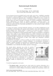
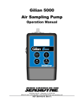
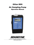
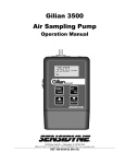
Laboratory/Field Audit Calibrator
NIST Traceable – ISO 9001:2000
1 TO 30 Lpm
Sensidyne, LP • 16333 Bay Vista Drive
Clearwater, Florida 33760 USA
800-451-9444 • +1 727-530-3602 • +1 727-539-0550 [fax]
web: www.sensidyne.com • e-mail: [email protected]
Gilian Challenger Air Calibrator
Important Note
If for any reason you are uncertain as to which Venturi is installed, recycle the I/O (off/on) switch. During
boot up, the bottom line on the screen will read SN XXXXXXL which indicates that the 1-6 lpm range unit is
installed. SN XXXXXXH, indicates that the 6-30 lpm range unit is installed.
Table of Contents.
Section
Topic
Page
1.0
Quick Start
4
2.0
Introduction
4
3.0
Specifications
6
4.0
Principle of Operation
10
5.0
Instrument Set Up
10
6.0
Using the Calibrator
11
7.0
Software
13
8.0
Maintenance
13
9.0
Safety
13
10.0
Warranty
13
Appendix A
NIST Traceability
14
Appendix B
Lubrication
16
Appendix C
Volumetric and Mass (Standard) Flow
16
Sensidyne Document No. 360-0110-01 (Rev B)
3
Gilian Challenger Air Calibrator
1.0 Quick Start
In order to put the instrument to immediate use as a Calibration/Audit device, follow these steps.
Step 1: Remove the instrument from its carrying case and turn it on.
Step 2: Install the correct Venturi for the flow rate range of interest.
#H 6-30 Lpm
#L 1.0-6 Lpm
Note: The Deluxe Model includes both Venturis. The Low Flow Model includes only the #L Venturi and
the High Flow Model includes only the #H Venturi.
Step 3: Provide tubing of the appropriate diameter to connect the Venturi to the instrument being
audited/calibrated.
Step 4: With air flowing, you may now read the screen to determine volumetric flow rate, ambient
temperature and barometric pressure.
For a diagram of the immediate application refer to Figure 1.
Note:
A Venturi MUST be matched to a unit by serial number. Swapping a Venturi from one Challenger to
another will cause accuracy loss.
2.0 Introduction
The Challenger air flow calibrators are manufactured for Sensidyne, LP by BGI, Inc.
All Challenger calibrators are based on the air flow measurement principle of the Venturi1. Our calibrators
are manufactured in an ISO 9000:2000 facility. The instruments provide an LCD indication of Volumetric
and Standard flow rate, barometric pressure and ambient temperature. It operates on four AA alkaline
energy cells (batteries).The electronics are all housed in the control module.
The instrument is furnished with two auto ranging Ventura, which cover the flow rate range of 1 to 30
Lpm.
4
Sensidyne Document No. 360-0110-01 (Rev B)
Gilian Challenger Air Calibrator
Sensidyne Document No. 360-0110-01 (Rev B)
5
Gilian Challenger Air Calibrator
Figure 1 – “Quick Start” Application of Challenger
3.0 Specifications
Flow rate range:
1 – 30 LPM (± 0.75% or less) (Deluxe Model)
1 – 6 LPM (± 0.75% or less) (Low Flow Model)
6 – 30 LPM (± 0.75% or less) (High Flow Model)
-30° C to 55° C
-30° C to 55° C (± .5° C)
400 to 800 mm of Hg (± 5mm)
533 to 1067 mb
Temp. operational range
Temp. reading range
Barometric pressure range
Dimensions:
Control Module:
1.59 in. high ( 4.04 cm) X 3.90 in. wide ( 9.91 cm) X 7.70 in. long ( 19.61 cm)
Weight w/ Venturi 7.4 oz (209 g)
One complete instrument comprises:
6
Quantity
Description
Catalog/Part No.
1
Challenger
811-9911-03
4
Installed AA batteries
Replacements
obtained locally by user
1
Instruction Manual
Enclosed CD
1
Carrying Case
7013586
1
Software Disk
615-9901-01
1
Venturi H, 6-30 lpm
Contact Factory
1
Venturi L, 1-6 lpm
Contact Factory
Sensidyne Document No. 360-0110-01 (Rev B)
Gilian Challenger Air Calibrator
Replacement supplies (not included with initial purchase).
1 Pkg. of 3
Venturi socket “O” rings
811-9913-01
VENTURI
(3) O-RINGS
THROAT TAP
UPSTREAM
PRESSURE
TAP
VENTURI HOUSING
AIR FLOW PATH
3060
Figure 3 – Sectional View of Measuring Head
Sensidyne Document No. 360-0110-01 (Rev B)
7
Gilian Challenger Air Calibrator
AIR FLOW
TEMPERATURE
PROBE
DIFF. PRESSURE
SENSOR
VENTURI
MICRO PROCESSOR
TO SAMPLER
BAROMETRIC
PRESSURE
SENSOR
BP
Ta
Qa
Qs
:760mm 1013mb
:22.8
:10.02LPM
Batt
:10.10LPM
100%
LCD DISPLAY SCREEN
Figure 4- Schematic Diagram of Challenger
3061
8
Sensidyne Document No. 360-0110-01 (Rev B)
Gilian Challenger Air Calibrator
RS232 PORT
VENTURI
ON / OFF SWITCH
THERMISTER
HOUSING
Figure 5 – Challenger Assembly
Sensidyne Document No. 360-0110-01 (Rev B)
9
Gilian Challenger Air Calibrator
4.0 Principle of Operation
The calibrator measures volumetric flow rate by utilizing a pressure transducer to assess the pressure
drop caused by air being drawn through a Venturi. As the flow rate through the Venturi increases, the
pressure drop increases as the square root1. A four times increase in pressure drop yields twice the flow
rate. A desirable feature of the Venturi is that most of the pressure drop created by the instrument is
recovered in the expansion section of the Venturi. Therefore, measurements are made at nearly the true
operating conditions of the sampler.
The signal from the pressure transducer is sent to the microprocessor where, it is combined, via an
algorithm with information from the barometric pressure sensor and the ambient temperature
sensor. To eliminate “fluttering” of the on screen display, of flow rate, the first 20 readings are averaged
and then carried on as a rolling average. Barometric pressure and temperature are monitored and
displayed on a continuous basis, when the instrument is switched
on. A cutaway diagram of the measuring head is shown in figure 3 and a schematic diagram of the
system is shown in Figure 4.
5.0 Instrument Set-up
Remove the instrument from its carrying case. The only control is an off/on switch on the end cap.
Switch the instrument on and the screen will boot into the main idle display screen for whatever Venturi is
installed. If no Venturi is installed, or the low range is installed then the boot screen will look like this:
The Challenger
Version 2.500
SN000004-L
If the low range is installed no change will occur, to the screen. If the high range was installed or it is
now installed, there will be a brief message:
VENTURI CHANGED
The boot screen will then have the following appearance:
The Challenger
Version 2.500
SN000004-H
A Venturi is changed (installed) in the following manner. With the Venturi held vertically, plain end
downwards (hose nipple up), plunge the Venturi into the hole in the top of the socket with a slight rotary
motion. Be certain that there is sufficient lubricant on the “O” rings within the recess. (See appendix B
about lubrication). At this point the instrument will automatically reboot and autorange to the selected
Venturi.
BP
Ta
Qa
Qs
10
:760mm 1013mb
:22.8
:10.02LPM
Batt
:10.10LPM
100%
Sensidyne Document No. 360-0110-01 (Rev B)
Gilian Challenger Air Calibrator
Using a short length of elastomeric tubing, connect the sampler under test to the top of the Venturi and
turn it on. The volumetric flow rate will now appear on the screen as shown above.
Important points to be noted concerning the utilization of the calibrator
A. When starting the Venturi must have no air flowing through it.
Every time the instrument is switched on, it re-zeros itself. If air is flowing, that flow rate will be
set as zero.
B. In order to perform the most precise measurement audit, it is necessary for the device to be in
thermal equilibrium with the ambient environment in which the sampler to be tested is located.
The best procedure is to deploy the calibrator for 10 minutes prior to the test, in the vicinity of the
sampler to be audited. Additionally, if the calibrator is subject to a temperature change of more
than five degrees, during use, it should be removed from the flowing air and rebooted.
C. When the calibrator is switched on XX % battery is displayed on the screen. So long as more
than 10% is indicated, it is safe to proceed, in that, at least one hour of power is available. The
test is now ready to be performed.
D. Never use a Venturi in a Challenger if the serial numbers do not match. Venturi and Challenger
are factory calibrated as a unit.
6.0 Using the calibrator
6.1 To perform an audit
One of two procedures should now be performed.
Procedure A. Turn off the sampler to be audited. Connect the calibrator to the inlet to the
sampler with, user provided tubing. Turn on the calibrator, wait for the screen to finish the
startup boot, then turn on the air sampler.
Procedure B. With the sampler to be audited running, when the calibrator screen has finished
its startup boot, connect the measuring tube to the instrument under test
When using Procedure B, connecting tubing to a running pump, may cause momentary instability
in the air samplers flow control circuit. Once the air samplers flow rate indicator stabilizes, the
reading may be taken. A simple audit data format is shown in Table 1. This may be taken as a
guide to designing a form suitable for your specific needs.
6.2 To perform a calibration.
The procedures and calculations for using the instrument to calibrate a sampler are the same as
an audit, except that one should set the sampler to the exact flow rate required.
Sensidyne Document No. 360-0110-01 (Rev B)
11
Gilian Challenger Air Calibrator
Table 1 Audit Data Format
Audited Instrument:
Make:___________________________ Model:_____________________ S/N:________________
Date:__________________ Time:________________ Calibrator S/N:________________________
Flow Rate – Lpm
Sampler:___________
Calibrator:___________
% diff. = [(Calibrator-sampler)/ Calibrator]x100
Allowed diff. = 4%; Pass________ Fail_________
Ambient Temp. – C
Sampler:___________
Calibrator:___________
Allowed diff. = ± 2 C; Pass________ Fail_________
Barometric Pressure – mm of Hg
Sampler:___________
Calibrator:___________
12
Allowed diff. = ± 10 mm; Pass________ Fail_________
Sensidyne Document No. 360-0110-01 (Rev B)
Gilian Challenger Air Calibrator
7.0 Software
Software for the Challenger is subject to upgrade periodically. Contact Sensidyne to see if your unit may
be upgradeable to the latest version.
8.0 Maintenance
Beyond battery replacement, the only part of the instrument requiring attention is the flow passage
through the Venturi. After long periods of use, some atmospheric dust can coat the interior flow surfaces.
The presence of such a deposit may be ascertained by viewing the interior of the Venturi under bright
light; direct overhead sunlight being preferable. Glance into the interior, from either end, seeking any
discoloration of the surface. If it is determined that cleaning is required, use the following procedure.
Rinse the entire Venturi body in warm soapy water. Any deposits, which are not floated away, may be
removed externally with a soft cloth. If internal deposits are not removed by soaking, the best procedure
is to immerse the unit in an ultrasonic bath containing soapy water. If an ultrasonic bath is not available,
judicious use of a pipe cleaner is recommended. Following cleaning, the Venturi may be dried utilizing
compressed air, or if not available, allowed to air dry.
9.0 Safety
There are no owner serviceable components in the instrument other than the Venturi socket “O” rings and
the four AA batteries. These should only be replaced with good quality alkaline energy cells and should be
promptly removed when expired, to prevent leakage and chemical damage to the electronic components.
When the instrument is placed in long term storage (more than two months) always remove the batteries.
Even though there is no reason to disassemble the electronics box, should the need arise, always remove
the batteries before proceeding further.
Adjustable potentiometers are contained within the electronic housing, which are factory set during
calibration. If these are turned, the calibration will be lost and factory recalibration will be required.
10.0 Warranty Information
Sensidyne warrants this equipment to be free from defects in workmanship and material. We make no
warranty, express or implied, except as set forth herein. Sensidyne's liability under this warranty extends
for a period of one (1) year from the date of Sensidyne's shipment. It is expressly limited to repairing or
replacing at the factory during this period and at Sensidyne's option, any device or part which shall within
one year of delivery to the original purchaser, be returned to the factory, transportation prepaid and
which on examination shall in fact be proved defective.
Sensidyne assumes no liability for consequential damages of any kind. The purchaser, by acceptance of
this equipment, shall assume all liability for consequences of its misuse by the purchaser, his employees
or others. This warranty will be void if the equipment is not handled, installed, or operated in
accordance with our instructions. If damage occurs during transportation to the purchaser, Sensidyne
must be notified immediately upon arrival of the equipment. Return transportation charges are collect.
Sensidyne Document No. 360-0110-01 (Rev B)
13
Gilian Challenger Air Calibrator
A defective part in the meaning of this warranty shall not, when such part is capable of being repaired or
replaced, constitute a reason for considering the complete equipment defective. Acknowledgment and
approval must be received from Sensidyne prior to returning parts or equipment for credit. Sensidyne
makes engineering changes and improvements from time to time on instruments in its product line. We
are under no obligation to retrofit these improvements and/or changes into instruments which have
already been purchased.
No representative of ours has the authority to change or modify this warranty in any respect.
Appendix A. NIST Traceability
A1.0 Introduction
NIST traceability for the calibrator is established with the use of devices which are of themselves
traceable and for which, the factory holds current traceability certificates. Calibrations are performed
under a set of ISO 9001:2000 procedures, subject to annual audit. During a flow rate calibration, the
room temperature is established with an ASTM certified/traceable thermometer. Barometric pressure
and absolute pressure are established with electronic manometers. These are backed by three Primary
Standard Mercury Instruments/
A2.0 Flow Rate Calibration
A schematic diagram of an instrument undergoing flow rate calibration is shown in Figure 1A. Two
traceable critical Venturi are utilized for this purpose. While the calibrator utilizes barometric pressure
and ambient
temperature to constantly display readings of volumetric flow rate, the initial Venturi
calibration is performed and normalized to a base value. While any values are sufficient, “Engineering
Standard Values” of 20C and 760mm of Hg have been selected. Utilizing an Excel spreadsheet, the
flow rate vs. pressure drop equation for each individual Venturi, under test, is determined. This
equation is then installed in the individual units microprocessor.
A3.0 Barometric Pressure Calibration
The barometric pressure sensor is set to match the actual current barometric pressure as determined
by a Mercury barometer. A negative pressure of 150 mm of Hg is applied to the barometric pressure
transducer and the output reading is adjusted to comply with BP – 150mm.
A4.0 Temperature Calibration
The Thermistor provided for measurement of ambient temperature is of a very high standard and are
batch tested at the temperature extremes of –20 C and +55 C, utilizing an ASTM certified/traceable
thermometer as a reference.
14
Sensidyne Document No. 360-0110-01 (Rev B)
Gilian Challenger Air Calibrator
DIGITAL TEMPERATURE
VACUUM
PUMP
20° C
MERCURY
BAROMETER
TRACABLE
CRITICAL VENTURI
MERCURY
MANOMETER
VENTURI PRESSURE DROP
MANOMETER
CALIBRATOR
VENTURI
CONTROL
VALVE
Figure A1- Schematic Diagram of Calibration Setup
2313
Sensidyne Document No. 360-0110-01 (Rev B)
15
Gilian Challenger Air Calibrator
A5.0 Recalibration
Recalibration is immediately necessary if physical damage has occurred to such an extent that the
instrument is rendered inoperable. In such cases, an instrument will be recalibrated as part of the
repair procedure. There are no moving or wear parts in the instrument, therefore, baring physical
damage, there is no reason for recalibration, except as required by ISO, company or regulatory
requirements. These requirements are almost universally on a one-year basis, after being placed in
service. Units received for recalibration will be thoroughly inspected and any requisite repairs will be
performed prior to recalibration.
Appendix B. Lubrication
There is one point which requires careful lubrication it is the three “O” rings inside the socket into which the
Venturi is inserted. They should be sparingly lubricated with the tip of the finger.
General purpose automotive grease seems to be the most successful all around lubricant.
Appendix C. Volumetric and Mass (Standard) Flow.
There are two ways that practitioners of air sampling measure and talk about flow rate.
Those doing compliance sampling for Industrial Hygiene/Occupational Health speak of Volumetric or Actual
Air Flow rates. It is the volume of air at the existing pressure and temperature at the sampling site. The US
EPA also specifies this type of measurement for PM2.5. Electronic meters usually read out in volumetric flow
rate or QA. Mass flow meters read out in Qs. The Challenger reads out in both.
EPA, for Politico Legal, reasons uses QS known as Standard or Mass Air flow rate for reporting PM10. This
means that the flow rate is reported to Standard conditions. For the US EPA, these conditions are 25 C and
1 atmosphere pressure. (1 Atmosphere = 760 mm of Hg = 29.92 in of Hg = 1013.25 millibars = 1013.25
hecto Pascals).
Because the mass of air flowing could be calculated from QS it has come to be called Mass flow.
Throughout most of the world QS is not usually referred to as mass flow and it is to a different standard. The
conditions outside of the U.S. are 0 C and 1013.25 mb.
The equations relating QA. and QS are:
QS = Qa * (BPa/760)*(298.15/(Ta+273.15)) For U.S. applications when Ts=25 C and BPs=760 mm of Hg
QS = Qa * (BPa/1013.25)*(273.15/(Ta +273.15)) For world applications when Ts=0 C and BPs=1013.25 mb
The screen which is the output of The Challenger is explained below:
16
Sensidyne Document No. 360-0110-01 (Rev B)
Gilian Challenger Air Calibrator
BP in hecto Pascals
(millibars)
BP in mm of Hg
Running on
battery Power
Ambient Temp.
BP
Ta
Qa
Qs
:760mm 1013mb
:22.8
:10.02LPM
Batt
:10.10LPM 100%
Actual Flow Rate at Local BP and T Ambient
Standard Flow Rate
(Actual Corrected to Standard Conditions)
3064
References
1.
2.
3.
Fan Engineering, R. Jorgensen, ed. Buffalo Forge Co, Buffalo, NY. 6th Ed. 1961.
US EPA FRM 40 CFR Part 53, Federal Register, July 18, 1997.
Measurement Systems, E.O. Doeblin, McGraw-Hill Inc., New York, NY. 4th Ed. 1990.
Sensidyne Document No. 360-0110-01 (Rev B)
17
Notes
Sensidyne, LP • 16333 Bay Vista Drive
Clearwater, Florida 33760 USA
800-451-9444 • +1 727-530-3602 • +1 727-539-0550 [fax]
web: www.sensidyne.com • e-mail: [email protected]
U KA S
AMTAC MEDIQA
QUALITY
MANAGEMENT
061
ISO 9001:2000 Registered