1
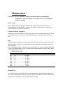
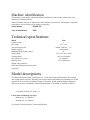
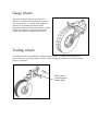
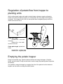
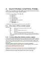
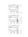
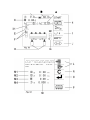
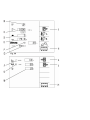
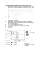
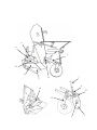
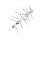
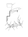
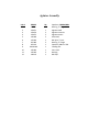
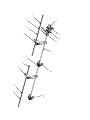
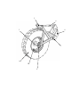
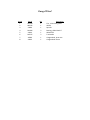
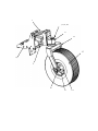
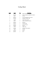
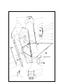
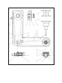
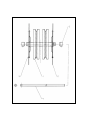
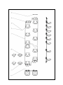
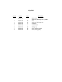
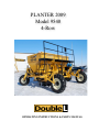
PLANTER 2009
Model 9540
4-Row
OPERATING INSTRUCTIONS & PARTS MANUAL
2
TABLE OF CONTENTS
Warranty Policy-----------------------------------------------------------Safety Information--------------------------------------------------------Maintenance----------------------------------------------------------------Preparing a New Machine------------------------------------------------Tractor Requirements-----------------------------------------------------Operating The Planter-----------------------------------------------------Trouble shooting----------------------------------------------------------- Parts List Table of Contents-----------------------------------------------
3
PAGE
3
8
14
17
19
22
34
37
4
P.O. Box 597
American Falls, ID 83211
Phone: 208.226.5592
Fax: 208.226.5934
Warranty Policy
I.
The Purpose of Warranty
Warranty assures the purchaser that should a defect in material or workmanship occur during
the warranty period, Double L will assume specific repair responsibilities, as listed in the
warranty statement. The warranty statement is to be provided to each purchaser of each piece
of new equipment. Warranty begins on the date the product is delivered to the original
purchaser of the product. Once the warranty period has begun, it cannot be stopped or
interrupted.
II.
Dealer Responsibilities
The following responsibilities are to be performed when the dealer delivers a product to the
purchaser or otherwise places it into warranty service:
1. Complete the Warranty Registration Form and forward to Double L within 30 days of the sale of the
product. Warranty reimbursement is contingent upon product registration.
2. Review warranty statement, operator’s manual and complete delivery report with purchaser to
assure understanding of purchaser’s responsibilities as related to warranty, service and the proper and
safe operation of the product. Purchasers should be advised to have failed parts repaired or replaced
immediately upon failure and that continued use will result in additional damage and excessive wear.
3. Contact manufacturer prior to beginning repair or replacement of failed parts to make certain that
the cost of repairs are consistent with the value of the product when sold. Warranty requests for units
in dealer’s inventory may be submitted to Double L when defects are noted in products prior to the
retail sale of that unit.
4. Provide warranty and service repairs as directed by Double L Service Repair Bulletins or other
instructions.
5. All warranty work must be completed within 30 days of failure. Notify Double L’s Warranty
Department if repairs will require more than 30 days after failure for an extension. No claim will be
accepted for warranties that exceed this 30-day period.
6. No warranty will be allowed on units delivered to the retail customer prior to the full payment of
that unit to the manufacturer.
7. If diagnostic time is required, contact Double L prior to beginning the warranty repair for approval.
III.
Double L’s Responsibilities
1. Reimbursement for parts used in warranty repair will be credited only when the parts are purchased
from Double L
2. Dealer should use parts from their parts inventory first. In the event that parts must be shipped from
Double L, freight will be paid by the Dealer, and will be shipped by the most economical means to
arrive in the shortest possible time. Air, Next Day Air, Priority and other special shipment methods
requested by the dealer will be at customer’s expense.
3. Labor is not paid on the warranty associated with repair parts purchased by the retail customer that
are used on a product that is not currently in warranty time frame.
4. Reimbursements for repairs made by outside sources (not dealer personnel) will be made for those
services deemed necessary for the resolution of the warranty by Double L’s Warranty Department.
Outside repair invoices must have prior approval from Double L’s Service Department and must be
attached to the warranty claim after approval.
5
IV.
Other Warranty Provisions
The following guidelines are to be followed when performing warranty repairs:
1. In all cases, the most economical repair should be performed unless otherwise directed. Credit will
not be allowed for assemblies, or groups, if it is practical to make the repair with individual parts. In
some cases, the assembly, or group price may be less than the total of the parts and labor required to
complete the repair. In those cases, an assembly, or group, may be used.
2. Only those parts provided by Double L are covered under Warranty. The use of parts from other
sources will not be eligible for warranty consideration.
3. All parts removed during warranty repair should be held for a period of 90 days after the warranty
claim has been submitted to Double L These parts can be discarded if disposition or return request
hasn’t been made during this period. Parts that are returned to Double L for which credit has not been
issued can be returned upon dealer request within 30 days of claim disposition. These parts will be
discarded after the 30-day period.
4. Double L reserves the right to deny or reverse any and all warranty claims for parts, labor, or
miscellaneous charges when errors are found or warranty provisions are abused or fraudulent claims
are submitted.
5. Warranty reimbursement is not possible:
a. If parts returned are not cleaned and properly identified, or if they are damaged in return
shipment due to poor packaging.
b. When failure falls under the "limitations" as identified in the Warranty Statement.
c. When Double L has requested the return of certain parts, assemblies or information and has
not received material within 30 days of date posted on return request.
d. On claims due to damage or shortage that are obviously the responsibility of dealer or the
delivering carrier.
e. On the entire claim when warranty policy and provisions are not followed.
All dealers will warranty their technician’s work to the purchaser and will indemnify Double
L from such claims.
Service Bulletins
Service Bulletins will be issued when necessary to alert dealers of special repairs. Each
Bulletin will give detailed directions and procedures to complete the service.
V.
Procedures For Completion Of Warranty Form
1. Dealer number, name and address - record number, name and address of dealership that has
performed warranty repairs and requests reimbursement.
2. Customer name and address and telephone number - record name, address and telephone number of
original purchaser of the warranted product.
3. Purchase Date - date when product was delivered to customer.
4. Serial Number - record the serial number of the machine on which repairs were performed.
5. Failure Date - record date when failure occurred.
6. Model - record model name or number.
7. Hours/Acres used - record number of acres or hours the product was used prior to failure.
8. Dealer Signature - Signature of dealer, or dealer’s representative, verifying repairs are complete.
9. Parts Required - record all service parts used to make necessary repairs. Include quantity, part
number, description and list price.
6
10. Labor Hours - record time taken to perform repairs. (Repair time ONLY - Travel time is not
allowed)
11. Labor Rate - record your normal retail shop rate or the rate specified in Warranty Policy,
whichever is less.
12. Total Labor Amount - multiply hours X rate to get total labor expense.
13. Total Parts - total list price of parts used.
14. Dealer Comments - please record a brief description of failure and probable cause.
VI.
Use of Photos
Pictures should be attached to the dealer’s claim when their inclusion will help identify
the condition of the part being repaired or replaced, and thus assisting in approval of the
claim. In many cases, the use of photos may eliminate the need to return parts for
evaluation. Photos will not be returned unless specifically requested.
VII.
Delayed Warranty Repairs
Warranty repairs should be scheduled and performed as soon as possible after notification of
dealer and Double L There may be circumstances that require the use of the product for a
short period of time by the retail customer or the availability of repair parts necessary to
complete the repairs will require the work to extend past the 30 day period. In those cases,
the dealer must notify Double L in writing of the extenuating circumstance and advise that
the continued use of the product will not enlarge the warranty claim. These claims will then
be processed as if the product is still within the warranty period.
VIII. Denied Claims
Dealers will be notified of a denied claim in writing that will state the reason for the denial.
The dealer has the right to appeal this claim and must do so within 30 days of notification of
denial. If there has been no appeal within the 30 days period the claim will be considered
closed.
Limited Warranty Statement
Double L warrants each new Double L product to be free from defects in material and
workmanship. This warranty is applicable only for the normal service life expectancy of the
product or components, not to exceed 12 consecutive months from the date of delivery of the
new Double L product to the original purchaser.
Genuine Double L replacement parts and components will be warranted for 30 days from
date of purchase, or the remainder of the original equipment warranty period, whichever is
longer. Under no circumstances will it cover any merchandise or components thereof, which,
in the opinion of the company, has been subjected to misuse, unauthorized modifications,
alteration, an accident or if repairs have been made with parts other than those obtainable
through Double L
The Company in no way warrants engines, batteries, tires or other trade accessories since
these items are warranted separately by their respective manufacturer.
Our obligation under this warranty shall be limited to repairing or replacing, free of charge to
the original purchaser, any part that, in our judgment, shall show evidence of such defect,
provided further that such part shall be returned within thirty (30) days from date of failure to
7
Double L, routed through the dealer and distributor from whom the purchase was made,
transportation charges prepaid.
This warranty shall not be interpreted to render Double L liable for injury or damages of any
kind or nature to person or property. This warranty does not extend to the loss of crops, loss
because of delay in harvesting, or any expense or loss incurred for labor, substitute
machinery, rental or for any other reason.
Except as set forth above, Double L shall have no obligation or liability of any kind on
account of any of its equipment and shall not be liable for special or consequential
damages. Double L makes no other warranty, expressed or implied, and, specifically,
Double L disclaims any implied warranty or merchantability or fitness for a particular
purpose. Some states or provinces do not permit limitations or exclusions of implied
warranties or incidental or consequential damages, so the limitations or exclusion in
this warranty may not apply.
This warranty is subject to any existing conditions of supply which may directly affect our
ability to obtain materials or manufacture replacement parts.
Double L reserves the right to make improvements in design or changes in specifications at
any time, without incurring any obligation to owners of units previously sold.
No one is authorized to alter, modify or enlarge this warranty nor the exclusion, limitations
and reservations.
8
General Safety
Before operating, adjusting or servicing the machine it is important that the safety
instructions in this manual are carefully read and understood by those, which are directly
concerned.
While all care and attention has been taken in the design and production of this machine, as
with all machinery there remains a certain amount of risk to personnel while the machine is
in use. It is strongly recommended that users and operators take all possible precautions to
ensure both their own safety and that of the others that may be in the vicinity.
Read and observe the safety instructions in this manual. Safety is your responsibility!
RECOGNIZE SAFETY INFORMATION
This is the safety-alert symbol. When you see this symbol on your
machine or in this manual be alert to the potential for personal injury.
Follow recommended precautions and safe operating practices.
UNDERSTAND SIGNAL WORDS
A signal word – DANGER, WARNING, or CAUTION – is used with the safety-alert
symbol. DANGER identifies the most serious hazards.
DANGER or WARNING safety signs are located near specific hazards. General precautions
are listed on CAUTION safety signs. CAUTION also calls attention to safety messages in
this manual.
FOLLOW SAFETY INSTRUCTIONS
Carefully read all safety messages in this manual and on your machine safety signs. Keep
safety signs in good condition. Replace missing or damaged safety signs. Be sure new
equipment components and repair parts include the current safety signs. Replacement safety
signs are available from your dealer.
Learn how to operate the machine and how to use controls properly. Do not let anyone
operate without instruction.
Keep your machine in proper working condition. Unauthorized modifications to the machine
may impair the function and/or safety and affect machine life.
If you do not understand any part of this manual and need assistance, contact your dealer.
9
PREPARE FOR EMERGENCIES
Be prepared if a fire starts.
Keep a first aid kit and fire extinguisher handy.
Keep emergency numbers for doctors, ambulance service, hospital, and fire department near
your telephone.
WEAR PROTECTIVE CLOTHING
Wear close fitting clothing and safety equipment appropriate to the job.
Operating equipment safely requires the full attention of the operator. Do not wear radio or
music headphones while operating machine.
HANDLE CHEMICAL PRODUCTS SAFELY
Direct exposure to hazardous chemicals can cause serious injury. Potentially hazardous
chemicals used with Double L equipment include such items as lubricants, paints, and
adhesives.
A Material Safety Data Sheet (MSDS) provides specific details on chemical products:
physical and health hazards, safety procedures, and emergency response techniques.
Check the MSDS before you start any job using a hazardous chemical. That way you will
know exactly what the risks are and how to do the job safely. Then follow procedures and
recommended equipment. (Contact Double L for MSDS’s on chemical products used with
Double L equipment.)
USE SAFETY LIGHTS AND DEVICES
Slow moving tractors, self-propelled equipment and towed implements or attachments can
create a hazard when driven on public roads. They are difficult to see, especially at night.
Avoid personal injury or death resulting from collision with a vehicle.
Whenever driving on public roads, use flashing warning lights and turn signals according to
local regulations. For some equipment, install extra flashing warning lights.
Keep safety items in good condition. Replace missing or damaged items.
PRACTICE SAFE MAINTENANCE
Understand service procedure before doing work. Keep area clean and dry.
10
Never lubricate, service or adjust machine while it is moving. Keep hands, feet, and clothing
from power-driven parts. Disengage all power and operate controls to relieve pressure.
Allow machine to cool.
Securely support any machine elements that must be raised for service work.
Keep all parts in good condition and properly installed. Fix damage immediately. Replace
worn or broken parts. Remove any buildup of grease, oil or debris.
Disconnect electrical cable before making adjustments on electrical systems or welding on
machine.
REMOVE PAINT BEFORE WELDING OR HEATING
Avoid potentially toxic fumes and dust.
Hazardous fumes can be generated when paint is heated by welding, soldering, or using a
torch.
Do all work outside or in a well-ventilated area. Dispose of paint and solvent properly.
Remove paint before welding or heating:
If you sand or grind paint, avoid breathing the dust. Wear an approved respirator.
If you use solvent or paint stripper, remove stripper with soap and water before welding.
Remove solvent or paint stripper containers and other flammable material from area. Allow
fumes to disperse at least 15 minutes before welding or heating.
AVOID HEATING NEAR PRESSURIZED FLUID LINES
Flammable spray can be generated by heating near pressurized fluid lines, resulting in severe
burns to you and bystanders. Do not heat by welding, soldering, or using a torch near
pressurized fluid lines or other flammable materials. Pressurized lines can be accidentally
cut when heat goes beyond the immediate flame area.
AVOID CONTACT WITH MOVING PARTS
Keep hands, feet and clothing away from power driven parts. Never clean, lubricate or adjust
machine when it is running.
AVOID HIGH-PRESSURE FLUIDS
Escaping fluid under pressure can penetrate the skin causing serious injury.
11
Avoid the hazard by relieving pressure before disconnecting hydraulic or other lines.
Tighten all connections before applying pressure.
Search for leaks with a piece of cardboard. Protect hands and body from high-pressure
fluids.
Spray from high-pressure nozzles can penetrate the skin and cause serious injury. Keep
spray from contacting hands or body.
If an accident occurs, see a doctor immediately. Any fluid injected into the skin must be
surgically removed within a few hours or gangrene may result. Doctors unfamiliar with this
type of injury should reference a knowledgeable medical source.
DISPOSE OF WASTE PROPERLY
Improperly disposing of waste can threaten the environment and ecology. Potentially
harmful waste used by Double L includes such items as oil and filters.
Use leak-proof containers when draining fluids. Do not use food or beverage containers that
may mislead someone into drinking from them.
Do not pour waste onto the ground, down a drain, or into any water source.
Inquire on the proper way to recycle or dispose of waste from your local environmental or
recycling center.
12
Machine Safety
Be careful when other people are close by!
Never start the machine when people are close by tractor or machine. Never stand between
the tractor wheels and machine. The width and height of the potato planter seed hopper
create a large blind spot behind the machine. Exercise extra caution when backing up.
Use of the machine
The machine should be used only for the purpose it has been designed for.
Use personal protection devices
Do not wear loose clothing, which might catch in any of the moving parts. In dusty
conditions an approved mask must be used.
Take care of excessive noise level. Some tractor/implement combinations, depending on
conditions, may cause noise level beyond 85dB at the operator’s ears. In these conditions ear
protection must be worn. Keep cab windows and doors closed to reduce noise level.
The machine must be connected to a correctly sized tractor
The weight of the tractor must correspond to the maximum weight of the machine when
operated. Follow domestic law and regulations.
Connecting machine to tractor.
If connection should be carried out with drawbar, one of the parts (tractor or machine’s
drawbar) must have a clevis. The drawbar pin must be secured with a lock pin.
Observe national regulations regarding road transport. Some countries require the use of
safety chain when a trailed machine is towed along public roads.
Think of safety while operating the machine
Stop the tractor engine and remove the ignition key prior to carrying out repairs, cleaning,
lubrication or maintaining the machine.
Safety guards
Make sure all guards are in good order and fitted correctly. Do not attempt to start the
machine before ensuring this.
Some machine options may require the use of a PTO shaft. Pay particular attention to the
plastic guards of the PTO shaft. If damaged they must be replaced. The chain locks of the
guards must always be fitted on a suitable place on the tractor and the machine to prevent the
outer plastic guards turning.
13
Hydraulics
Be very careful when dealing with hydraulics. Use eye protection and gloves. Escaping
hydraulic oil under pressure might penetrate into the skin and cause serious infection. See a
doctor if you have been exposed to injury.
Take care that nobody is close to the machine when the hydraulic functions are being
operated.
When uncoupling machine and when leaving tractor/machine
When uncoupling, all hydraulic functions must be in neutral position. The machine must be
lowered to the ground and be safely secured. If the machine has parking chocks they should
be used at the wheels. Never allow children to play or stay near agricultural machinery.
Drive safely
Beware of your responsibility, - carelessness or negligence may cause serious injury or even
death.
Prior to transporting the machine along public roads, check wheel bolts and couplings.
Disconnect or lock the hydraulic system.
Drive carefully. Reduce speed when turning and driving on uneven ground. Take care that
trailed machine does not start swinging or become unstable.
Please be aware of the danger of overturning when working on slopes and in soft ground.
Reduce load.
Lights
The owner and operator is responsible of providing correct lamps and reflectors on the
machine when transported on public roads. Comply with public regulations.
Safety equipment
Always carry first aid equipment on the tractor. Also observe the regulations concerning fire
extinguisher. When working with burning materials like hay and straw a fire extinguisher
must be available at all times.
Spare parts
For safety reasons use only original spare parts. The use of non Double L spare parts will
cause the warrantee to be invalid.
Maintenance
Take care that the machine is properly maintained and kept in good safe working condition.
Never change the basic technical construction of the machine.
14
Maintenance
CAUTION: Review and follow all safety instructions before performing any
maintenance. To prevent injury, never lubricate or service equipment
while it is running.
Roller Chains
Roller chains should be kept tight and lubricated. Adjustment of the roller chains is
accomplished by moving the idler. Lubricate the chains every 200 hours with SAE 30 or
heavier engine oil or an aerosol chain lube.
Cup Belt Tension & Alignment
Adjusters are provided at the top of each planter leg to tension and align the cup belt. Do not
over tighten cup belt. In order to avoid stretching the belts, reduce the tension when not in
use.
Bolts
Belt and chain roller bolts as well as mounting bolts should be checked at least every season
and tightened as necessary. Pay extra attention to the frame bolts connecting the front and
rear cross tubes.
Check thoroughly all bolts of drawbar, top section's hinge pins, wheels and wheel shafts after
1 hour of use and thereafter weekly. All other bolts and nuts should be checked after 8 hours
of use and thereafter weekly.
Bolt tensioning torque
Thread size
Torque
M5
3/16” ......................... 50.5 lb.in
M6
¼”... .......................... 7.3 lb.ft
M8
5/16” ......................... 17.7 lb.ft
M10 3/8” . ......................... 35.4 lb.ft
M12
½”... ......................... 62.7 lb.ft
M16 5/8” . ..........................155 lb.ft
M20
¾”... ..........................295 lb.ft
M24
1”.... ..........................737 lb.ft
Dirt Build Up
It is often necessary to clean dirt off of accumulation points, especially when conditions are
wet. Some of the points to watch are: pulleys, rollers, chutes, bowls, belt slides and all drive
and hydraulic components. Stop the planter before cleaning.
Controls
Check wirings for damage or corrosion. Check all plugs and sockets. Keep command panel
and electric cabinet clean. Clean with a moist cloth, and avoid running water.
Storage
a.
b.
c.
d.
e.
f.
Clean excessive dirt build up from machine.
Lubricate all roller chain.
Apply a light coat of oil to all extended cylinder rods.
Store in dry shelter if possible or cover all rubber parts.
Loosen all roller chain drives.
Cover electric valves
Welding on machine
Disconnect the command panel and the electric cabinet before any welding is done on the
machine.
Maintenance hydraulics
Check the filter element every 50 acres or at least once a season. The filter element should be
replaced for every 250 acres being planted and always once a season.
Caution!
Release pressure in the system before opening the filter housing.
Keep hydraulic oil clean! Clean hydraulic oil will prevent excessive wear and premature
failure of components. Replace the tractor filter and oil as per manufacturer’s instructions.
Cleaning
We recommend the use of pressured air when cleaning the machine. Thus there is less risk of
damaging the bearings of the machine. If high pressure water is used, keep clear of bearings and
electric components.
Assure that piston rods are kept free from aggressive chemicals in order to avoid corrosion.
Machine identification
The machine’s serial number and the manufacturer’s address are found on the number plate of the
machine. See illustration below.
The serial number and year of manufacture for this machine is given below. This number is important
with regard to service and the correct supply of spare parts.
Serial number
:958009-121
Year of manufacture
:2009
Technical specifications
Model
Number of rows
Row width
Seed spacing intervals
Hopper capacity
Minimum filling height, potatoes
Guage wheels
Trailing wheels
Disc-rollers for coverers
Working speed
Weight empty machine
Electronic planting monitoring system
Area meter
9560
6
(34" - 38")
infinite variable 4” – 31”
13,000 pounds
93”
12.4"-24" 8 layer w/ribs
14L-16.1 Floatation
16” diameter
2.5-6.5 miles/hour
Model descriptions
The Model 9580 potato planter from Double L is a 8 row semi-mount trailed machine. The planting
units include double cup belts, adjustable gate between hopper and planting unit, adjustable row width,
hydraulic drive powered by the hydraulic pump of the tractor, infinite planting distance adjustment,
rigid furrow openers and manually controlled planting depth. The machine is available as follows:
8-row basic machine, row width 36"
Choose between following cup types:
- Planting cup 2.6” diameter
- Planting cup 2.9” diameter
The planter is delivered with 16” diameter hilling discs.
1. PREPARING A NEW MACHINE
Start up of new machine
Read the operator’s manual. Great care must be taken when starting a brand new machine for the first
time. Incorrect assembly, faulty operations etc. may cause expensive repairs and loss of profit. The
Double L product guarantee does not cover damage occurring when the instructions given in this book
are not followed.
Carefully do as described below when starting a new machine.
Check that the machine is mounted correctly and that it is not damaged. Assure that electric wirings
have length and position that allow machine to move without causing any damage to the wirings.
Check the connections between tractor and machine.
Check that the roller chains are tensioned and correctly positioned on the sprockets.
Check that the drive rollers on top of both planting tubes are equally adjusted in order to assure cup
belts run straight.
Lubricate the machine according to lubrication instructions.
Check wheel bolts torque setting.
Row width control
Check that row width is in accordance with customer’s specifications.
The row width could preferential be ordered directly from the factory, since it is difficult to change the
row width after initial factory assembly.
6-row basic machine, row width 34"
6-row basic machine, row width 36"
6-row basic machine, row width 38"
Hilling discs
The Hilling disc frame is attached to the planting unit
with metric 12 mm bolts.
The hilling disc down pressure can be adjusted by
changing the preload spring pressure. Hilling disc
position can be varied by moving the top of the
spring rod to different anchor positions on the platter
leg.
Hilling disc
The roller disc down pressure can be adjusted by turning the nut above the compression spring.
The width distance between the discs, and disc angle, is adjustable by using the different holes in the
roller discs arms, and then locked by the center bolt.
Gauge wheels
The gauge wheels mounted on the front of the
planter are set with the dual turnbuckles located on
each side of the tire. It’s easiest if the adjustment
amount is first estimated, and then make the
adjustment with the tractor drawbar raised up. In this
manner, the turnbuckles will turn easily since the
weight of the planter is supported by the tractor.
Trailing wheels
The trailing wheels are hydraulically controlled from the tractor. To change wheel height, add or
remove ram stops from each hydraulic cylinder. Make sure that all cylinders have the same number
and size of ram stops.
Add or remove
cylinder stops to
change depth.
2.
TRACTOR REQUIREMENTS
Tractor Horsepower—225 horsepower minimum.
Hydraulic connection
Single acting output with free return, continuous oil flow, capacity 12 gallons/min.
One double acting hydraulic valve.
Electrical supply
12V, standard 12mm.
IMPORTANT! Ensure all electrical contacts and the sockets are well connected in order to
avoid a power supply cutoff due to vibrations. Even a very short cutoff will start the computer
test procedure.
3.
TRACTOR CONNECTIONS
Road Transport
Prepare the planter for road transport:
A removeable transport axle and hitch have been provided for transporting the planter between fields.
The hitch and rear axle can be raised and lowered with hydraulic pressure from the tractor. The
hydraulic cylinders can be stored on the planter and do not need to be removed along with the hitch
and axle. Limit tow speed to 15 miles per hour, and do not tow planter with potatoes in the tank.
Although the hydraulics can lift the planter up away from the ground for clearance while towing, do
not rely on the hydraulics to hold planter up while towing. After raising the planter, make sure the
hitch and axle are pinned with the provided bolts. Do not actuate hydraulics after hitch and tow axle
are pinned in place.
Hydraulic drive system
Components
The hydraulic drive system on this machine consists of the following items.
- Two or three spools valve block
- Oil motor for driving planting units
- 2-way check valves for trailing wheel cylinders
- Check valves for ensuring proper flow direction
- High pressure oil filter
- Hydraulic circuit for raising and lowering the tow hitch and tow axle.
Connecting the hydraulic valve
When connecting hydraulic hoses to tractor, the pressure hose goes to the oil filter on the planter, the
second hose is return. The hydraulic valve is very sensitive to contamination, and if contaminated oil
reaches the valve, the valves proportional control will be compromised.
Connecting tractor hydraulics
The trailing wheels are connected directly to the tractor hydraulics for lowering /raising, and operated
by the keypad. The icon showing hopper up/down controls the wheel height on Double L planters.
4.
OPERATING THE MACHINE
Seed potato size
Uniformly sized potato seed results in an improved yield and optimal planter performance.
Recommended grading (square sieve):
Min.
Max.
Max length
size
size
of potatoes
Large cup ø74mm ................................ 1.5” ...........................2 3/8”.............................4”
Large inserts (white) ........................... 1 3/8”.............................2”................................3”
Small inserts (green) .............................. 1”.............................. 1.5” ..............................2”
Working speed
Depends on cup belt speed, i.e. the chosen spacing.
Small spacing = low speed
Large spacing = high speed
Spacing (inch) x 0.39 = optimal working speed (miles per hour).
Spacing (cm) x 0.25 = optimal working speed (km/h).
Round seed can be planted at larger speed while oblong and cut seed should be set at lower speed.
Belt agitation
Set to minimize misses and doubles. Six positions
(Fig. 45a/A).
Minimum agitation = Large potatoes, high belt
speed
Maximum agitation = Small potatoes, low belt
speed
Mechanic agitation
9 positions (Fig. 45b/A)
Regulation of potato flow from hopper to
planting units
Set the choke plates (angle and length) to obtain balance between supply and planting.
Potato level should normally be approx. 6-8 inches below the lower edge of the hopper’s
front plate. If the hopper bowl is too full, the cup belt does not agitate properly and more
double seed sets will occur.
Choke plate angle:
Increase flow – turn crank
clockwise
Reduce flow – turn crank
counter clock wise.
Choke plate length: (slotted bolt
holes)
Increase flow - shorten plate
Reduce flow - lengthen plate
Emptying the potato hopper
Empty all accessible cups. Open the bottom hatches and empty the hopper. If the flow
blocks, move the belts. Finally turn the belts in order to empty the planting tubes. Reposition
the hatches.
It is possible to empty the hopper by engaging the drive of the planter from the electronic
keypad, see the section covering the control system.
5
ELECTRONIC CONTROL PANEL
NOTE! The screen displays may differ slightly from the figures included in this manual.
Some function icons do not apply to Double L planters.
The electronic control system includes (Fig. 50):
A Control panel
B Black box
C Wheel sensor
D Drive shaft sensor
E Valve bank cable
F Depth control sensor (optional)
G Battery cable
H Power supply cable
I
Panel cable
The black box is fitted behind the right-hand side panel of the planter.
5.1 The keys of the control panel
See Fig. 51.
A-B
Arrow keys for moving the marker on the screen
C
Not in use
D-E
± keys for change of screen values
F
Not in use
G
OK key confirming the selection/storing the new value
J-O
Function keys with variable function, see soft key display on screen
When operating the ± keys (D-E) with no parameter selected, the screen contrast
is adjusted.
5.2 Connecting the tractor power supply
In order to start using a machine with electronic control system, the power supply to the black
box must be connected. Insert the plug in the power supply socket of the tractor. If the tractor
does not include a proper power supply socket, a new one should be fitted. A battery cable
with fuse is included with the machine. Connect cable to the tractor's battery when fitting the
battery cable.
Note that red cable should be connected to the + terminal of the battery.
On the rear side of the panel an ON/OFF switch is provided (Fig. 51/T). When turn ON the
control system is powered and the screen lights up.
Wait then about 25 seconds for the main menu.
See Fig. 51 for the description of the keys of the control panel. See Fig. 51 regarding
description of symbols on the screen and the varying function of the function keys.
Disconnect the power supply if the machine is not used for several days.
5.3 Panel display
Operating the machine:
A
Start/stop of the machine
Note that forward speed should exceed 0.5 km/h to activate planter drive. Lower the
machine and push the "START" key, see Fig. 52 (A). The key symbol will thus
change to show "STOP". Press "STOP" key to stop the planter drive and continue
for at least 2 meters in order to cover the end of the row. Thereafter raise the
machine. During the planting the planting units will empty. It is recommended to
maintain a fairly constant level of tubers in the planting units in order to obtain a good
result.
B
C
D
E
F
G
H
Changing between menus for operating the hydraulic functions on the
machine
Raise hopper (rear tires on Double L planters)
Lower hopper (rear tires on Double L planters)
Machine up/reduce planting depth
Machine down/increase planting depth
Increase agitation of cup belt
Decrease agitation of cup belt
Main menu:
A Showing the progress of speed
B Wanted planting width
C Indicates the area registration which is active, and total areal in
hectares(ha) which have been driven on this area registration
D1 Wanted fertilizer amount Kg/ha for fertilizer hopper A
D2 (Wanted fertilizer amount Kg/ha for fertilizer hopper (B/C)
E Indicates the agitation intensity Min-Max on the cup belt
F Shows if the automatic hopper leveling sensor is activated and also
the potato level in the planting unit
G Shows if the automatic depth control sensor is activated and also the
depth of the machine
H Shows if the planting sensor is activated 2-8 rows and also the error
planting for each row (0-100%).
I Lower hopper for loading
J Empty planter with cup belt
M1 Total time the machine has been driven in raised position
M2 Total time the machine has been driven in lowered position
M3 Total area with planted potatoes
M4 Average speed during work
Area registration:
K
L
M
N
O
P
Change to area registration
Change between area registration 1-20
Indicate for every area registration
Reset the registrations
Activates the chosen area registration
Change to the main menu without activating chosen area registration
B
A
Programming/calibrating the machine
Programming the control:
A Service menus
B Activate the wheel sensor. If this is set to symbol "tractor" the wheel sensor
is activated and the wheel on the planter has to rotate for starting the
machine. If this is set to symbol "hand" the sensor is not activated. And the
planter is starting directly after the start has been pressed. You then have
to add the speed of the tractor manually in the main menu. (Fig. 53 A)
C Calibration of the wheel diameter. Measure 100 meter (109 yd)
Press the arrow key (Fig 51 A-B) until the "START" symbol is flashing.
Press "OK" key and drive 100m (109 yd).
Press once again "OK" key to store the correct numbers of pulses for
100 meters (109 yd) This number will typically be around 600 pulses per
100 meters. Loose soil has more tire slip, thus fewer pulse counts per 100
meters. After an initial field calibration, pulse count can be manually fine
tuned. Ideally, the speed indicated on the planter should match that indicated
by the tractor. If planter control speed is below that measured by the tractor
speedometer, adjust the pulse count number upward. If it measuring over
what the tractor speedometer reads, adjust this number downward. Changes
in soil conditions within the same field may result in this calibration fluctuating
slightly from tractor speed, but is should stay fairly close.
D Number of planting units. After confirming "OK" the current must be
turned off/on, so the value in the software will be stored.
E Actual row with
F Turn off/on the planting control
G Choose between metric and imperial measuring value. After confirming
"OK" the current must be turned off/on, so the value in the software
will be stored.
H Go directly to the main menu
I Next page
J Activates the hopper level sensor and add the wanted level of potato in
the planting unit from 0-100%, 0% gives a low level of potatoes, and
100% gives high level of potatoes.
K Activate the depth sensor. Adjust the planting depth by setting the value
from 0-100%. 0% gives a shallow or none planting depth, and 100% gives
maximum planting depth
M Define the intensity fo the agitation for each press on++or-- (Se Fig. 57
G-H)
L Prevous page
I Next page
Programming of the machines sensors and hydraulic valve:
A
B
C
D
E
F
G
L
H
This value is centering the proportional valve for the drive of the planting
belt. The value for the center position of the valve is about 500 ppg. If the
belt is starting to late this value has to increase. Or if the belt is going to
fast during planting this value has to reduce
This value is centering the proportional valve for the drive of the planting
belt. The value for the center position of the valve is about 50%. If the
fertilizer chain is starting to late this value has to increase. Or if the chain
is going to fast during planting the value has to reduce.
The active time for the hopper filling sensor
Ton = time cylinder is active
Toff = time for next reacting
The active time for the depth sensor
Ton = time cylinder is active
Toff = time for next reacting
After enter the "STOP" the machines runs (X) meters before lifting in
front. And then (X) seconds before lifting up the rear of the machine, after
the front lifting has started.
(x) seconds the lifting in front is activated
(x) seconds the lifting of the rear of the machine is activated
Prevous page
Main menu
5.4 Alarms displayed on screen
5.4.1. Misses (empty cups)
Too many empty cups on row unit number given in the alarm display.
Check the tuber level and the adjustments of the choke plates, agitators etc.
5.4.2 Cup belts does not run
No oil supply to the drive motor. Check the hydraulic system.
5.4.3 Too low voltage
Check the electric connections of control system and the power supply system of the tractor.
5.4.4 Too high speed of the cup belts
Faulty planting distance setting or too high forward speed on the tractor.
5.4.5 Varying planting distance
Faulty oil supply to the planter.
5.4.6 Field registration
Push key K (Field registration) in order to activate the field registration display.
Alarm display
6.
Trouble shooting
Symptom
Inaccurate planting:
Misses
Action
Remove/exchange inserts
Reduce belt agitation
Reduce working speed
Increase choke plates openings
Doubles
Use cup inserts
Increase belt agitation
Increase working speed
Reduce choke plate openings
Doubles and misses
Reduce variations of seed size
Potatoes out of line in the row
Increase the planting depth to make a
deeper V- shaped furrow.
Potatoes out of center of ridge
Adjust coverers’ position according to
planter’s row centers
Faulty planting depth
a) Rigid furrow opener
Lift or lower land wheels
Varying planting depth
a) Rigid furrow openers
Reduce hopper filling
Covering:
Too little soil covering
Too much soil covering
Increase depth of coverers
Reduce depth of coverers
Sharp top of ridge
a) Disc coverers
Increase distance between pair of discs
b) Ridging shovel/ridging hood
Move shovel wings inwards
Wide furrow
a) Roller discs
Increase distance within the pair of discs
Narrow furrow
a) Roller discs:
Decrease distance within the pair of discs
Notes
PARTS MANUAL
Planter Leg ............................................................................................................................... 39 Spindle Assembly—Hilling Disc ............................................................................................. 41 Agitator Assembly.................................................................................................................... 43 Drive......................................................................................................................................... 45 Gauge Wheel ............................................................................................................................ 47 Trailing Wheels ........................................................................................................................ 49 Hydraulic & Control Circuits................................................................................................... 51 Planter row unit ........................................................................................................................ 53 Transmission ............................................................................................................................ 55 Top Shaft .................................................................................................................................. 57 Cup Belt.................................................................................................................................... 59 9
8
3
10
1
11
2
7
6
14
13
12
4
5
Planter Leg
Item # 1 2 3 4 5 6 7 8 9 10 11 12 13 14 Part # 41550 41558 42050 41832 21165 135393 42036 133698 133646 133641 134841 134641 134640 133647 Qty (per row) 1 1 1 2 2 1 1 2 2 2 4 1 1 2 Description Shoe, complete assembly Frog Hilling disc frame Disc hub, complete assembly Hilling disc Spring, compression Adjuster, hilling disc Urethane spring Parallel arm, upper Parallel arm, lower Bushing Hilling disc arm, LH Hilling disc arm, RH Spring arm 5
4
9
6
3
8
7
3
2
4
1
Spindle Assembly—Hilling Disc
tem # 1 2 3 4 5 6 7 8 9 Part # 134727 134728 015333 015326 014731 134732 008178 022279 014349 Qty (per hub) 1 1 2 2 1 1 1 1 1 Description Spindle, planter hub Hub, planter Bearing cup Bearing cone Cap, hub Hub, flange Castle nut, 3/4‐NF Seal, shaft Washer, 3/4 flat 12
10
9
11
6
5
6
4
4
3
1
5
7
2
3
8
7
Agitator Assembly
Item # 8 1 2 3 4 5 6 7 8 9 10 11 12 027139 Part # 016321 133671 133670 133672 135448 137266 017389 027139 UH210346 135400 135449 136119 Qty 1 4 1 2 2 2 2 2 1 1 1 2 1 Sprocket, 60B15 1.25B Description Bearing, 1" flange Agitator shaft Agitator eccentric Agitator mount All‐thread Ball joint, ½ inch. Bearing, 1” flange Sprocket, 60B15 1.25B Feeding disc Disc crank Bushing Belt flap 3
8
7
2
4
9
10
11
1
5
2
4
10
8
3
6
Drive
Item # 1 1 2 3 4 4 5 6 7 8 9 10 11 Part # 137526 137526 134836 133699 42035 42034 001990 017389 027716 133704 41868 134815 134837 Qty 1 1 2 2 1 1 3 3 1 2 1 3 3 Description Main drive shaft‐‐34" row spacing, 4 row Main drive shaft‐‐36" row spacing, 4 row Hex shaft, long Hex shaft, short Planter transmission with speed sensor Planter transmission Sprocket Bearing, 1" flange Hydraulic motor Hex coupler Hydraulic motor mount Bearing mount Chain guard 5
6
3
8
7
1
2
4
Gauge Wheel
Item # 1 2 3 4 5 6 7 8 Part # 021159 003725 41850 011306 42614 017027 36936 42613 Qty 1 1 1 2 1 2 1 1 Description Tire, 13.0 x 24.0 grader Wheel Spindle Bearing, pillow block 2" Wheel fork Turnbuckle Gauge wheel, pivot arm Gauge wheel mount 3
7, 8, 9, 10
6
11
15
1
2
12
13
14
Trailing Wheels
Item # 1 1 2 3 4 5 6 7 8 9 10 11 12 13 14 15 Part # 41553 41553A 36851 36851A 021648 40238 40237 020424 020426 019649 021099 41799 011306 41850 007860 134771 Qty 3 1 1 1 1 1 1 1 1 1 1 1 2 1 1 1 Description Mount assembly Mount assembly, w/depth limit switch Lift arm Lift arm w/depth sensor mount Hydraulic cylinder, 4x8 Swivel wheel mount Swivel, complete assembly Dust cap Retaining ring Bushing, bronze Spacer Caster, fork Bearing, 2" pillow block Spindle Wheel Tire Hydraulic & Control Circuits
Item # 1 2 3 4 5 6 7 8 9 10 11 11 12 13 14 15 16 Part # 134883 134881 134882 134879 134880 029110 011696 027716 004645 134901 135298 135351 027838 027750 027751 021648 007053 Qty 1 1 1 1 1 1 1 1 2 1 1 1 2 2 2 1 1 Description Keypad ‐ Planter Sensor, inductive ‐ Planter Control Box Whisker Switch Sensor, shaft Switch, limit Coupler, 1” x 1” Motor, hydraulic 10.0 1” L.P. C‐L,RS Cable, control 16F Filter, hydraulic high pressure Valve, 3 Bank Valve, 2 Bank Valve, restrictor SAE #8 Valve, body + P.O. check cart Valve, hydraulic pilot dual Cylinder, hydraulic 4 x 6 AG Valve, hydraulic select manual Planter row unit
Item # 1 2 3 4 5 6 7 8 9 10 11 12 13 14 15 16 17 18 19 20 21 22 23 24 25 26 27 28 29 30 31 Part # UH210015 UH210045 UH210048 UH210032 UH210033 UH210036 UH210037 UH210150 UH210152 UH210027 UH210072 UH210080 UH210129 UH870718 UH210135 UH210135 UH210085 UH215049 UH215026 UH216725 UH210160 UH215091 UH219250 UH215092 UH870632 UH210142 UH210144 UH215093 UH222628 UH215081 UH222599 Qnty 4 ‐ ‐ 4 4 4 4 4 8 8 4 8 4 8 4 4 4 4 4 8 4 8 8 8 8 8 8 8 8 4 4 Description Planting unit 3700 not used on Double L planter not used on Double L planter Side plate, LH Side plate, RH Box corner, LH Box corner, RH Yoke Inlet guide assembly Guide grill Planting tube lining, 3700 Adjusting screw Bottom bearing, 3700 Ball bearing, 6203 2RS C3 Bottom pulley, 3700 Support rail, 3700 Lock gate, 3700 Bolt, D10 Spring Roller, ø50 and bolt Belt rail, 3700 Bearing holder Bearing housing, D55‐D36 Guide bearing Bearing 6006‐2RS Tension screw assembly Guide washer D13 Compression spring Washer Agitator Agitator lever Transmission
Item # 1 2 3 4 5 6 7 8 9 10 11 12 13 14 15 16 17 18 19 20 21 22 23 24 25 26 27 28 29 30 31 Part # UH210015 UH210045 UH210048 UH210032 UH210033 UH210036 UH210037 UH210150 UH210152 UH210027 UH210072 UH210080 UH210129 UH870718 UH210135 UH210135 UH210085 UH215049 UH215026 UH216725 UH210160 UH215091 UH219250 UH215092 UH870632 UH210142 UH210144 UH215093 UH222628 UH215081 UH222599 Qnty 4 ‐ ‐ 4 4 4 4 4 8 8 4 8 4 8 4 4 4 4 4 8 4 8 8 8 8 8 8 8 8 4 4 Description Planting unit 3700 not used on Double L planter not used on Double L planter Side plate, LH Side plate, RH Box corner, LH Box corner, RH Yoke Inlet guide assembly Guide grill Planting tube lining, 3700 Adjusting screw Bottom bearing, 3700 Ball bearing, 6203 2RS C3 Bottom pulley, 3700 Support rail, 3700 Lock gate, 3700 Bolt, D10 Spring Roller, ø50 and bolt Belt rail, 3700 Bearing holder Bearing housing, D55‐D36 Guide bearing Bearing 6006‐2RS Tension screw assembly Guide washer D13 Compression spring Washer Agitator Agitator lever Top Shaft
Item # 1 2 3 4 Part # UH210120 UH210116 UH215141 UH217031 Qnty 2 4 4 1 Description Top pulley D254 Guiding pulley Stop ring Drive shaft Cup Belt
Item # 1 Part # UH210175 Qnty 2 2 3 4 5 6 7 8 UH210179 UH210180 UH215156 UH215158 UH215154 UH210182 UH210184 80 80 8 4 80 80 80 Description Rubber belt Steel cup, 3700 large, zinc + powder coat Steel cup, 3700 large, zinc connector connector pin Guiding cup Insert, medium (white) Insert, small (green) Double L
2698 Lakeview Road
P.O. Box 597
American Falls, Idaho 83211
(208) 226-5592
www.doublelinc.com