1
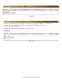
User Manual VP-25A1 Implement industry control with Linux Technique Warranty All products manufactured by ICP DAS Inc. are warranted against defective materials for a period of one year from the date of delivery to the original purchaser. Warning ICP DAS Inc. assume no liability for damages consequent to the use of this product. ICP DAS Inc. reserves the right to change this manual at any time without notice. The information furnished by ICP DAS Inc. is believed to be accurate and reliable. However, no responsibility is assumed by ICP DAS Co., Ltd. for its use, or for any infringements of patents or other rights of third parties resulting from its use. Copyright Copyright © 2011 by ICP DAS Co., Ltd. All rights are reserved. Trademark The names used for identification only maybe registered trademarks of their respective companies. License . The user can use, modify and backup this software on a single machine The user may not reproduce, transfer or distribute this software, or any copy, in whole or in part. ViewPAC-23(25)A1 User Manual:1 Contents 1. Introduction ............................................................................................. 4 1.1 Overview.................................................................................................................... 6 1.2 Mounting the Hardware........................................................................................... 10 2. Installation of ViewPAC-25A1 SDK .................................................... 16 2.1 Quick Installation of ViewPAC-25A1 SDK ........................................................... 16 2.2 The ViewPAC-25A1 SDK Introduction.................................................................. 18 2.2.1 Introduction to Andorid SDK ........................................................................................ 18 2.2.2 Introduction to ADB ....................................................................................................... 19 2.2.3 Introduction to Eclipse ................................................................................................... 20 2.2.4 Download the ViewPAC-25A1 SDK .............................................................................. 21 3.The Architecture of library in the ViewPAC-25A1............................. 22 4. ViewPAC-25A1 System Settings .......................................................... 24 4.1 Settings for the ViewPAC-25A1 Network............................................................... 24 4.1.1 IP、Netmask and Gateway............................................................................................ 24 4.2 SD Card Usage ........................................................................................................ 25 4.2.1 Mount SD Card............................................................................................................... 25 4.2.2 Umount SD Card ............................................................................................................ 26 5. A Simple Example for the ViewPAC-25A1......................................... 27 5.1 Get started with the Eclipse Platform ...................................................................... 27 5.1.1 Create a new project ....................................................................................................... 27 5.1.2 Add project reference for an application ...................................................................... 29 5.1.3 Design and Build an application program.................................................................... 30 5.1.4 Execute the application on the ViewPAC-25A1 ........................................................... 31 5.2 Get started with the ADB tool ................................................................................. 32 5.2.1 Design an application program ..................................................................................... 32 5.2.2 Add project reference for an application ...................................................................... 33 5.2.3 Build an application program........................................................................................ 34 5.2.4 Execute the application on the ViewPAC-25A1 ........................................................... 34 ViewPAC-23(25)A1 User Manual:2 6. Introduction of ViewPAC-25A1 Serial Ports...................................... 36 6.1 Introduction of COM1 Port of ViewPAC-25A1...................................................... 37 6.2 Introduction of COM2 Port of ViewPAC-25A1...................................................... 37 6.3 Introduction of COM3 Port of ViewPAC-25A1...................................................... 38 7. Additional Support................................................................................ 39 7.1 N-Port Module ( I-8114W, I-8112W, etc.) Support................................................ 39 7.2 ScreenShot Support ................................................................................................. 41 7.3 Network Support...................................................................................................... 43 7.4 System Recovery Support........................................................................................ 45 Appendix A. Service Information ............................................................ 46 Internet Service :............................................................................................................ 46 Manual Revision :.......................................................................................................... 47 ViewPAC-23(25)A1 User Manual:3 1. Introduction The ViewPAC combines LinPAC, a color graphic display and a keypad in one unit. It is equipped with a PXA270 CPU running the Android 1.6 operating system, multiple communication interfaces (USB, Ethernet, RS-232/485 and audio ports), 3 I/O slots, a 3.5”/5.7” TFT LCD and a rubber keypad. The Android 1.6 operating system has many advantages, including stability, hard real-time capabilities, small core size, and multiple development environments (ViewPAC SDK for Linux and Windows environments, Android I/O driver and GUI software), etc. The Android operating OS demands less system resources from the embedded controller and is therefore the best fit for it because of the embedded controller has some limitations in system resources. It is for this reason that the ViewPAC-25A1 embedded controller has been published to be a new generation product from ICP DAS and the Embedded-Linux OS has been adopted into the ViewPAC-25A1. The ViewPAC-25A1’s main purpose is to allow the numerous enthusiastic Linux users to control their own embedded systems easily within the Linux Environment. ViewPAC-23(25)A1 User Manual:4 Fig. 1-1 ICP DAS provides the library file - icpdas.jar which includes all the functions from the I-7000/8000/87000 series modules which are used in the ViewPAC-25A1 Embedded Controller. The icpdas.jar is desiged specially for the high profile I-7000/8000/87000 series modules on the Linux platform for use in the ViewPAC-25A1. Users can easily develop applications in the ViewPAC-25A1 by using Java Language. The various functions of the icpdas.jar are divided into the sub-group functions for ease of use within the different applications. The powerful functions of the ViewPAC-25A1 embedded controller are depicted in figure 1-1, which includes a USB(Card Reader, Camera …), Mouse, Keyboard, microSD card, Series ports(RS-232, RS-485), Ethernet(Hub…) and many I/O slots in the picture. In network communication, wireless transfer and Modem、GPRS、ADSL、Firewall are also supported. The ViewPAC is designed to provide convenient, flexible and simplified solutions for industrial and embedded applications. Compared with traditional IPC + PLC solutions, ViewPAC reduces overall system cost and space, and gives you all the best features of both IPC and PLC. ViewPAC-23(25)A1 User Manual:5 1.1 Overview The ViewPAC-2000 (hereafter referred to as VP-2000) family is a versatile unit that provides a wide variety of features in an extremely compact package. The VP-2000 is small, but offers many instructions normally only found in larger, more expensive systems. The modular design also offers more flexibility in the fast moving industry of control systems. There are two types of units in the standard VP-2000 family, VP-23A1 and VP-25A1. These units are the same except its touch screen size and keypad. The VP-25A1 includes several interfaces and peripherals that can be integrated with external systems. Here is an overview of the components and its descriptions. The details of these items are as follows: Fig. 1-2 Fig. 1-3 ViewPAC-23(25)A1 User Manual:6 ① LED Indicators The ViewPAC has three LED indicators. They are located on the top. Fig. 1-4 The LED indicators can be used to indicate the power status, OS status and Link/Act, as follows: LED Indicator L1/L2/L3 RUN PWR LAN1 State (Color) Meaning ON (Red) Control by user programmable OFF Control by user programmable ON (Green) OS is ON OFF OS is OFF ON (Green) Power ON OFF Power OFF ON (Green) Link active OFF Link inactive Blink (Green) Network activity ViewPAC-23(25)A1 User Manual:7 ② LCM Touch Screen A touch screen is a display screen that is responsive to contact by stylus pen or finger. Touch screens allow users to continually change and redesign the interface of a device. The screen size of the VP(H)-23A1 is 3.5” 320 x 240. The screen size of the VP(H)-25A1 is 5.7” 640 x 480. ③ Keypad The connector is a point at which a conductor from an electrical component comes to an end and provides a point of connection to external circuits. The connector has 10 pins and its pin assignments are as follows: A keypad is a set of buttons arranged as shown in the following figure. in a block or "pad" which usually bear digits, symbols and usually a complete set of alphabetical letters. If it mostly contains numbers then it can also be called a numeric keypad. Keypads are found on many alphanumeric keyboards and on other devices such as calculators, push-button telephones, combination locks, and digital door locks, which require mainly numeric input. ④ Rotary Switch The Rotary Switch is an operating mode selector switch which provides seven functions, the selection of operating mode and authorization control for the ViewPAC. For more information about the operating mode, please refer to Quick Start manual. ⑤ Micro SD Socket There is a Micro SD expansion slot which is used to increase memory capacity just in case 16 GB. ViewPAC-23(25)A1 User Manual:8 ⑥ Microphone and Earphone Jacks The VP-2000 has the microphone and earphone jack to the input and output of sound system. ⑦ USB Port The VP-2000 has a USB port to support the USB devices such as mice, keyboards and external USB hard drives. ⑧ COM3 (RS-232) Port Type: Male Baud Rate: 115200, 57600, 38400, 19200, 9600, 4800, 2400, 1200 bps Data Bits: 5, 6, 7, 8 Stop Bits: 1, 2 FIFO: 16 bytes Device node: /dev/ttyS1 Default Baud Rate: 115200 Parity: None, Even, Odd, Mark (Always 1), Space (Always 0) ⑨ Power Input and Frame Ground The VP-2000 has a power terminal on which it receives power for its operation. The terminal block has 3 pins and its pin assignments are as follows: ViewPAC-23(25)A1 User Manual:9 ⑩ Ethernet Port and Waterproof IP67 The VP-2000 has an Ethernet port which is opening on VP-2000 network equipment that Ethernet cables plug into. The Ethernet port with the waterproof for protection from dirt, oil, and sand. ⑪ COM2 (RS-485) The COM2 is a point at which provides a point of connection to external RS-485 devices. The COM2 has 2 pins, as follows: Device node: /dev/ttyS0 Default Baud Rate: 9600 1.2 Mounting the Hardware The ViewPAC can be mounted on a panel of maximum thickness 12 mm. Adequate access space can be available at the rear of the instrument panel for wiring and servicing purposes. The layout dimensions are shown below. Fig. 1-5 Fig. 1-6 To ensure proper ventilation for your ViewPAC, leave a minimum of 50mm space between the top and bottom edges of the ViewPAC and the enclosure panels. ViewPAC-23(25)A1 User Manual:10 Step 1: Prepare the panel and cut the hole to the specified size Fig. 1-7 Step 2: Attach the ViewPAC to the cut-out hole Fig. 1-8 ViewPAC-23(25)A1 User Manual:11 Step 3: Insert the panel mounting clips into the upper and lower ventilation holes Fig. 1-9 ViewPAC-23(25)A1 User Manual:12 Step 4: Screw the panel mounting clips to the panel Mounting screw: M4 x 35L Fig. 1-10 ViewPAC-23(25)A1 User Manual:13 1.3 Mounting the Waterproof The ViewPAC provides an IP67 waterproof connector which consists of the following components plugged in RJ-45 cable. Fig. 1-11 ViewPAC-23(25)A1 User Manual:14 Fig. 1-12 ViewPAC-23(25)A1 User Manual:15 2. Installation of ViewPAC-25A1 SDK Before you start, you should already have the Android SDK installed, and if you’re using Eclipse, you should have installed the ADT plugin as well. If you have not installed these, please see http://developer.android.com/sdk/installing.html “ViewPAC-25A1 SDK” consists of the following major items. z ViewPAC SDK library files z Demo files z Manuals From ftp://ftp.icpdas.com/pub/cd/linpac/napdos/vp-2000/vp-25a1/sdk, users can download the latest version of ViewPAC-25A1 SDK. Then follows below steps to install the development toolkit provided by ICP DAS for the application development of the ViewPAC-25A1 embedded controller platform easily. 2.1 Quick Installation of ViewPAC-25A1 SDK 1. Please insert the installation CD into your CD-ROM driver. 2. Run the “vp25a1sdk_for_windows.exe” file under the folder \Napdos\vp-2000\vp-25a1\SDK. Then click on the “Next” button, refer to Fig. 2-1. 3. Choose the option of “I accept the agreement” and click the “next” button, refer to Fig. 2-2 below. Fig. 2 -1 Fig. 2-2 ViewPAC-23(25)A1 User Manual:16 4. To starting install the ViewPAC-25A1 SDK, refer to Fig 2-3. 5. After successfully installing the software, please click on the “Finish” button to finish the development toolkit installation, refer to Fig. 2-4. Fig. 2-3 Fig. 2-4 6. Open the “C:\ICPDAS\VP25A1_SDK\” folder and see the content. Refer to Fig 2-5. Fig. 2-5 7. Start using the “ViewPAC Build Environment” by double clicking the shortcut for the “ViewPAC-25A1 Build Environment” on the desktop or by clicking through “ Start ”>” Programs ”>” ICPDAS ”>” ViewPAC-25A1 SDK ”>” ViewPAC-25A1 Build Environment ” icon. Then a special DOSBOX will be displayed in which we can compile applications for the ViewPAC-25A1. Refer to Fig. 2-6. Fig. 2-6 Once your Installation is complete, you can find the files for the library, manual and demo in the following paths. The icpdas.jar path is “C:\ICPDAS\VP25A1_SDK\lib". The manual files path is “C:\ICPDAS\VP25A1_SDK\manual” The demo path is “C:\ICPDAS\VP25A1_SDK\demo”. ViewPAC-23(25)A1 User Manual:17 2.2 The ViewPAC-25A1 SDK Introduction In this section, we will discuss some techniques that are adopted in the ViewPAC-25A1. Through our detailed explanations, users can learn how to use the ViewPAC-25A1 easily. ViewPAC-25A1 SDK is based on cygwin and it is also a Linux-like environment for Windows. It still provides a powerful GCC cross-compiler and an IDE (Integrated Development Environment) for developing ViewPAC-25A1 applications quickly. Therefore after you have written your applications, you can compile them through the ViewPAC-25A1 SDK into executable files that can be run in your ViewPAC-25A1 embedded controller. 2.2.1 Introduction to Andorid SDK The Android SDK includes a variety of tools that help you develop mobile applications for the Android platform. The tools are classified into two groups: SDK tools and platform tools. SDK tools are platform independent and are required no matter which Android platform you are developing on. Platform tools are customized to support the features of the latest Android platform. Fig. 2-7 ViewPAC-23(25)A1 User Manual:18 Fig. 2-8 For more detailed information, please refer to: http://developer.android.com/index.html 2.2.2 Introduction to ADB To install ADB, download the latest version of the Android SDK by following the instructions at http://developer.android.com/sdk. You will find adb in the tools directory. The Android Debug Bridge is very similar to your command prompt (DOS prompt). When you're in the ADB, you're accessing the phone itself as long as your VP-25A1 is connected. Fig. 2-9 ViewPAC-23(25)A1 User Manual:19 2.2.3 Introduction to Eclipse The Eclipse website provides all the downloads specific to the various Windows platform. Getting started with Android development using Eclipse IDE, user can refer to: http://www.eclipse.org/downloads/ , then install in D:\ Fig. 2-10 Fig. 2-11 Fig. 2-11 Fig. 2-12 And also download ADT tool (ADT Plugin for Eclipse) from http://developer.android.com/sdk/eclipse-adt.html. ViewPAC-23(25)A1 User Manual:20 2.2.4 Download the ViewPAC-25A1 SDK Users can download the latest version of ViewPAC-25A1 SDK for Windows system- vp25a1sdk_for_windows.exe from: ftp://ftp.icpdas.com/pub/cd/linpac/napdos/vp-2000/vp-25a1/sdk/ ViewPAC-23(25)A1 User Manual:21 3.The Architecture of library in the ViewPAC-25A1 The icpdas.jar is a library file, which is designed for I7000/8000/87000 applications. There are running in the ViewPAC-25A1 Embedded Controller using the Linux OS. Users can apply it to develop their own applications with Java language. In order to assist users to build their project quickly, we provide many demo programs. Based on these demo programs, users can easily understand how to use these functions and develop their own applications within a short period of time. The relationships among the icpdas.jar and user’s applications are depicted as Fig. 3-1: Fig. 3-1 ViewPAC-23(25)A1 User Manual:22 Fig. .3-2 Functions (1) in the icpdas.jar are the same as with the DCON.DLL Driver ( including Uart.dll and I7000.dll ) as used in the DCON modules (High profile I-7000 / I-8000 / I-87000 in serial communication ). You can refer to the DCON.DLL Driver manual which includes the functions on how to use DCON modules. The DCON.DLL Driver has already been wrapped into the icpdas.jar. Functions (2) of the icpdas.jar consist of the most important functions as they are specially designed for I-8000 modules in the ViewPAC-25A1 slots. They are different from functions (1) because the communication of I-8000 modules in the ViewPAC-25A1 slots are parallel and not serial. The ViewPAC-25A1 support an I/O expansion bus which can be used to implement various I/O functions. The functions in the icpdas.jar is specially designed for ViewPAC-25A1. Users can easily find the functions they need for their applications from the descriptions in Java_API_for_linux.pdf. ViewPAC-23(25)A1 User Manual:23 4. ViewPAC-25A1 System Settings In this section, we will introduce how to setup the ViewPAC-25A1 configuration. Let users can use the ViewPAC-25A1 more easily. 4.1 Settings for the ViewPAC-25A1 Network The ViewPAC-25A1 network setting includes two ways. One is DHCP and the other is “Assigned IP”. DHCP is the default setting after the ViewPAC-25A1 is produced and this way is easy for users. However, if your network system is without DHCP server, then users need to configure the network setting by using “Assigned IP”. 4.1.1 IP、Netmask and Gateway Using DHCP : Boot up ViewPAC-25A1 and click the “start/xterm” to open a “command Prompt”. Type in “vi /etc/network/interfaces” to open the network setting file. Remove “#” in the dhcp block and add “#” in the Assign IP block. Then type “:wq” to save the setting. Type “ifup eth0” to make the setting work. (Refer to the Fig 4-1) Fig 4-1 ViewPAC-23(25)A1 User Manual:24 Static IP: To get the Android browser to resolve address names, set the DNS server property. In the ADB shell, give the following command: “setprop net.dns1 xxx.xxx.xxx.xxx” where xxx.xxx.xxx.xxx is the IP address to your DNS server. 4.2 SD Card Usage The contents of SD card in the ViewPAC-25A1 is in the default path of /mnt/hda. Therefore, users can access the files of SD card in the directory. 4.2.1 Mount SD Card When you want to use the SD card, you can insert the SD card into the socket in the ViewPAC-25A1. It will be auto-mounted in the ViewPAC-25A1, and you can access the files of SD card in the /sdcard directory. Fig 4-2 Fig 4-3 ViewPAC-23(25)A1 User Manual:25 4.2.2 Umount SD Card Before you want to pull out the SD card from the ViewPAC-25A1, please see the following: Fig 4-4 ViewPAC-23(25)A1 User Manual:26 5. A Simple Example for the ViewPAC-25A1 In this section, we will introduce how to compile the Helloworld.java and transfer to the ViewPAC-25A1 by ADB tool. Finally executes this file via the ADB Server on the ViewPAC-25A1.In this example, no ICP DAS modules are used. If you want to use the modules of ICP DAS to control your system, you can refer to demo in Java_API_for_Linux.jar. 5.1 Get started with the Eclipse Platform 5.1.1 Create a new project Start Eclipse, select File > New > Android Project. This new the Android Project Wizard dialog. Enter a Project Name, and fill in all necessary fields. (refer to Fig.5-1) Fig. 5-1 ViewPAC-23(25)A1 User Manual:27 New <supports-screens> element lets you specify the device screen sizes and set Small Screens= "true", Normal Screens= "true", Large Screens= "true", Resizeable= "true", Any Density= " true" in your application's manifest. (refer to Fig.5-2) Fig. 5-3 Define your layout ―main.xml, set Layout height= "480dip" and Layout width= "640dip" in Properties table. (refer to Fig.5-4) Fig.5-4 To build a project automatically, click Project ¼ Build Automatically. (refer to Fig.5-5) Fig.5-5 ViewPAC-23(25)A1 User Manual:28 5.1.2 Add project reference for an application User can use a third party JAR(ex: icpdas.jar) in your application by adding it to your Eclipse project as follows: STEP 1: In the Package Explorer panel, right-click on your project and select Build Path. STEP 2: Select Add External Archives. (refer to Fig.5-6) Fig.5-6 STEP 3: Download icpdas.jar and select the JAR file. (refer to Fig.5-7) ( icpdas.jar > ftp://ftp.icpdas.com/pub/cd/linpac/napdos/vp-2000/vp-25a1/sdk/ ) Fig.5-7 ViewPAC-23(25)A1 User Manual:29 Adding external library to the ViewPAC-25A1 completely, see below: (refer to Fig.5-8) Fig.5-8 5.1.3 Design and Build an application program See the Package Explorer on the left. Click Helloworld.java ( Helloworld ¼ src ¼ com.example.helloworld ) and take a look at the revised code below: (refer to Fig.5-9) Fig.5-9 Finally, save the project and it will auto build the application. ViewPAC-23(25)A1 User Manual:30 5.1.4 Execute the application on the ViewPAC-25A1 Find the IP address of ViewPAC-25A1, please press Menu ¼ Dev Tools ¼ Terminal Emulator and enter the command “getprop” to get IP address. (refer to Fig.5-10, 5-11) Fig.5-10 Fig.5-11 Open a “ViewPAC-2000 Working Environment” which is a DOS Command Prompt (check if <Android sdk>/platform-tools/ directory first), and then using ADB shell to connect your ViewPAC-25A1 via TCP/IP. (refer to Fig.5-12) Fig.5-12 To uninstall the *.apk file, user can type “rm” command to remove it. (refer to Fig.5-13) Fig.5-13 ViewPAC-23(25)A1 User Manual:31 To run Helloworld.apk, please press Menu ¼ Hello, ICPDAS. (refer to Fig.5-14, 5-15) Fig. 5-14 Fig. 5-15 5.2 Get started with the ADB tool 5.2.1 Design an application program Start any editor. It may be Notepad or any other editor like TextPad or Editplus etc, and write a small Hello program. (refer to Fig.5-16) Fig. 5-16 ViewPAC-23(25)A1 User Manual:32 5.2.2 Add project reference for an application User can use a third party JAR(ex: icpdas.jar) in your application by adding it to your Android project as follows (refer to Fig.5-17): Fig. 5-17 Download icpdas.jar from: ftp://ftp.icpdas.com/pub/cd/linpac/napdos/vp-2000/vp-25a1/sdk/ And, make sure the PATH to the JDK and Android SDK are correct. Now to check value of CLASSPATH (refer to Fig.5-18, 5-19): Fig.5-18 5-19 ViewPAC-23(25)A1 User Manual:33 5.2.3 Build an application program In this section, we show you how to compile your JAVA program. STEP 1: Obtain and install a Java platform on the PC. STEP 2: Open a “DOS Command Prompt” such as “ViewPAC-2000 Working Environment” and change directories to the Java platform's bin folder STEP 3: Type the followint command to compile the Hello.java: (refer to Fig.5-20). Fig. 5-20 5.2.4 Execute the application on the ViewPAC-25A1 Open a “ViewPAC-2000 Working Environment” which is a DOS Command Prompt and check if <Android sdk>/platform-tools/ directory first, and then using ADB shell to connect your ViewPAC-25A1 via TCP/IP. (refer to Fig.5-21, 5-22, 5-23, 5-24) Fig. 5-21 Fig. 5-22 ViewPAC-23(25)A1 User Manual:34 Fig. 5-23 Fig. 5-24 ViewPAC-23(25)A1 User Manual:35 6. Introduction of ViewPAC-25A1 Serial Ports This section describes the function of the three serial ports (RS-232/RS-485 interface) in the ViewPAC-25A1 embedded controller (see Fig 6-1). The information in this section is organized as follows: z COM1 Port ─Internal communication with the I-87KW modules in slots z COM2 Port ─RS-485 (D2+, D2-; self-tuner ASIC inside; 2500VDC isolation) z COM3 Port ─RS-232 (TxD, RxD, CTS, RTS, DSR, DTR, CD, RI and GND; Non-isolation) COM port Definitions in VP-25A1 SDK None 2 (RS-485) 3 (RS-232) COM1 COM2 COM3 Device name None ttyS0 ttyS1 Default baudrate 115200 9600 115200 Fig. 6-1 User can try the stty command to query or setting COM port. For example, to modify baudrate 9600 to 115200 bps. of COM2 port: # stty -F /dev/ttyS0 ispeed 115200 ospeed 9600 ViewPAC-23(25)A1 User Manual:36 6.1 Introduction of COM1 Port of ViewPAC-25A1 COM1 is an internal I/O expansion port of the ViewPAC-25A1. This port is used to connect the I-87KW series module plugged into the ViewPAC-25A1 embedded controller. Users must use the serial command to control the I-87KW series module. For controlling the I-87KW module, you must input the Com-port parameters and call the Open_Com function to open the com1 port based on the appropriate settings. Finally, the user can call the ChangeToSlot(slot) function in order to change the control slot. This is like the serial address, and you can send out the control commands to the I/O module which is plugged into this slot. Therefore the module’s serial address for its slot is 0. 6.2 Introduction of COM2 Port of ViewPAC-25A1 This COM2 port provides RS-485 serial communication (DATA+ and DATA-) and is located on bottom-right corner in the ViewPAC-25A1. You can connect to the RS-485 device with modules like the I-7000, I-87k and I-8000 serial modules(DCON Module) via this port. That is, you can control the ICP DAS I-7000/I-87k/I-8000 series modules directly from this port with any converter. ICP DAS will provide very easy to use functions with icpdas.jar and then you can easily handle the I-7000/I-87k/I-8000 series modules. Fig. 6-2 ViewPAC-23(25)A1 User Manual:37 6.3 Introduction of COM3 Port of ViewPAC-25A1 This COM3 port is located on the right-upper corner on the ViewPAC-25A1. It is a standard RS-232 serial port, and it provides TxD, RxD, RTS, CTS, GND, non-isolated and a maximum speed of 115.2K bps. It can also connect to the I-7520 module in order to provide a general RS-485 communication. The COM3 port can also connect to a wireless modem so that it can be controlled from a remote device. ¾ Test in command line: (PC <--------------> COM3 of ViewPAC-25A1) A) Open “Hyper Terminal” of PC to monitor the process of update and the default COM3 port setting is 9600, 8, N, 1 B) Send data via COM3 port: In ViewPAC-25A1: Type command: echo test>/dev/ttyS1 And, user must be see the “test” in “Hyper Terminal” of PC C) Receive data via COM3 port: In ViewPAC-25A1: Type command: cat /dev/ttyS1 In PC: User can input some words in “Hyper Terminal” of PC And, user can see some words in ViewPAC-25A1. ViewPAC-23(25)A1 User Manual:38 7. Additional Support In this chapter, ICP DAS provides extra module supported and instructions to enhance ViewPAC-25A1 functionality and affinity. 7.1 N-Port Module ( I-8114W, I-8112W, etc.) Support The I-8114W/I-8144W and I-8112W/I-8142W modules provide four and two serial ports respectively. Users can insert them into the ViewPAC-25A1 slots. In this way, users can use more serial ports in the ViewPAC-25A1 and the expanded maximum number of serial port in the ViewPAC-25A1 will be thirty-three. The ViewPAC-25A1 is a multi-tasking uint, therefore users can control all the serial ports simultaneously. The serial port number of I-8114W and I-8112W modules are presented in the Fig.7-1 and Fig.7-2 and it is fixed according to their slot position in the ViewPAC-25A1. The Multi-serial port provides functions for installation of the RS-232/RS-422/RS-485 communication module driver. The table below shows the expansion RS-232/RS-422/RS-485 communication modules that are compatible with the ViewPAC. Item I-8112iW I-8114W I-8114iW I-8142iW I-8144iW RS-232 2 4 4 - RS-422/RS-485 2 4 Isolation 2500 Vrms 2500 Vrms 2500 Vrms 2500 Vrms Connector DB-9 x 2 DB-37 x 1 DB-37 x 1 Terminator block x 1 Terminator block x 1 User can try the stty command to query or setting COM port. For example, to modify baudrate 9600 to 115200 via COM5 port: # stty -F /dev/ttyS3 ispeed 115200 ospeed 115200 ViewPAC-23(25)A1 User Manual:39 Fig.7-1 Fig.7-2 How to use the I-8114W module in the ViewPAC-25A1? In this demo, we will control the I-7044 ( 8 DO channels and 4 DI channels ) module through the second serial port on the I-8114W plugged into the slot 2 on the ViewPAC-25A1. The address and baudrate of the I-7044 module in the RS-485 network are 02 and 115200 separately. Fig.7-4 is the control diagram. ViewPAC-23(25)A1 User Manual:40 Fig.7-4 7.2 ScreenShot Support Android ships with a debugging tool called the Dalvik Debug Monitor Server (DDMS), which provides port-forwarding services, screen capture on the device, thread and heap information on the device, logcat, process, and radio state information and SMS spoofing, location data spoofing, and more. This page provides a modest discussion of DDMS features; it is not an exhaustive exploration of all the features and capabilities (Refer to Fig 7-5, 7-6, 7-7, 7-8). Fig. 7-5 ViewPAC-23(25)A1 User Manual:41 Fig. 7-6 Fig. 7-7 ViewPAC-23(25)A1 User Manual:42 Fig. 7-8 7.3 Network Support Users can see open the web browser and input the web site address in the ViewPAC-25A1. ( Refer to Fig 7-9, 7-10, 7-11, 7-12 and 7-13) Fig 7-9 Fig 7-10 ViewPAC-23(25)A1 User Manual:43 Fig 7-11 Fig 7-12 Fig 7-13 3G wireless modem guide: Install loadable kernel module /lib/modules/2.6.29/sim5218.ko Execute command pppd call 3g & Device Node /dev/ttyUSB3 More information, please refer to: http://m2m.icpdas.com/m2m_layer2_gprs.html Accourding to the chip default baud rate is “115200” bps, wireless module and device node such as /dev/ttyUSB3, both of them should have same baudrate. User need to double check the system setting as following: 1) Enable ril support in /init.rc ViewPAC-23(25)A1 User Manual:44 2) Enable and check if device node is /dev/ttyUSB3 in /system/build.prop 3) Enable pppd_gprs support in /init.pac.rc Type in “pppd call 3g &” and then it will be connected to the internet automatically. Remember that the network interface should stop first. If users type in “ifconfig” will see the “ppp0” section. 7.4 System Recovery Support The ViewPAC-25A1 will determine if the system hang at booting, system will auto recovery and reboot. See the screenshot below to recovery image. ( Refer to Fig 7-14) Fig 7-14 Note: It will probably take 8 - 10 minutes. ViewPAC-23(25)A1 User Manual:45 Appendix A. Service Information This appendix will show how to contact ICP DAS when you have problems in the ViewPAC-25A1 or other products. Internet Service : The internet service provided by ICP DAS will be satisfied and it includes Technical Support, Driver Update, OS_Image, ViewPAC-25A1 SDK and User’s Manual Download etc. Users can refer to the following web site to get more information: 1. ICP DAS Web Site: http://www.icpdas.com.tw/ 2. Software Download: http://www.icpdas.com.tw/support/download/download.html 3. Java Supported Document : http://www.icpdas.com/download/java/index.htm 4. E-mail for Technical Support: [email protected] [email protected] ViewPAC-23(25)A1 User Manual:46 Manual Revision : Manual Edition Revision Date v1.0 2012.02 Revision Details First published ViewPAC-23(25)A1 User Manual:47