1
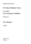
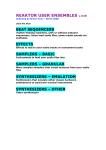
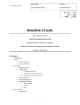
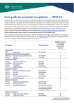
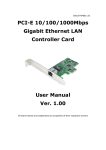
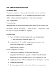
Fundamental Circuits Analysis Lab LAB Introduction to the Lab Experiments It is important for you to understand and observe safety rules and precautions used in the laboratory and in the field of Mechatronics. Objectives After completing this lab, you should be able to: • • • • • Perform and follow basic safety procedures Identify and sketch several basic electronic components Locate and record specifications on several laboratory instruments Adjust a power supply for proper output voltage Understand the layout and use a solderless breadboard Materials Required The following are quantities and descriptions of materials need in this lab experiment. 1 1 X 1 1 X Power Supply 0 – 12V DC at 1 Ampere DMM Miscellaneous components 12V DC incandescent Lamps Protoboard and connecting wire Power Supply and Multimeter user manuals or pdf files. 1 Fundamental Circuits Analysis Lab Discussion I t is very important for you to observe all safety rules and procedures while performing experiments in this Course. To ensure a safe workplace in the laboratory or in the field, you will be required to participate in a safety orientation lecture. Additional information is available at the Occupational Safety and Health Administration (OSHA) site: http://www.osha.gov/. The best way to lean and acquire electronic skills depends on your own personal learning style. These experiments are centered on the visual and tactile learner and promote hands-on learning. In this experiment you will be presented with pictorial and schematic symbols or pictures. The pictorial diagram shows a picture or sketch of the various components of a specific system and the wiring between these components. This simplified diagram provides the means to readily identify the components of a system and convey their basic shape. The pictorial diagram many not show the actual physical location or detailed information on the interconnecting wires. It does, however, show you the connection points on the components. Pictorial diagrams are helpful in identifying components in a system, tracing a circuit, which both facilitate troubleshooting and repair of equipment or systems. Refer to Figure 1-1 for several examples of pictorial components used in electronics. Figure 1-1 Component Pictorials 10 kΩ Resistor 10 µF Switch LED Capacitor A schematic diagram is a drawing or sketch that details the components is an electrical or electronic circuit by means of symbols. Schematic diagrams are a vital part of understanding and troubleshooting electrical and electronic systems. There are standards, (ANSI Y32.2 and IEEE 315.75) for schematic symbols; unfortunately some draftspersons take great liberty in selecting or modifying symbols and therefore you may find diagrams that do not follow these standards. Refer to Figure 1-2 for several examples of schematic symbols of components used in electronics. 2 Fundamental Circuits Analysis Lab Figure 1-2 Schematic Symbols Resistor LED Switch Capacitor Included with both pictorial and schematic diagrams are reference designators which are simply labels to identify each component and usually there will be the component’s value. For example resistors are usually labeled with an R, followed by a numerical value that is unique to that resistor and distinguish it from other resistors in the diagram. Therefore if a diagram has three resistors and three capacitors they could have reference designators of R1, R2, R3, C1, C2, and C3. Electrical and Electronic instruments are used in the laboratory to measure quantities, view graphically waveforms and provide external signals to simulate circuits or systems. Electronically controlled instruments may use analog displays, digital readouts, or graphics panels to provide information to the technician. One powerful and versatile tool is the Multimeter; which gets its name from being able to measure multiple circuit quantities. Multimeters are available in two main types: analog and digital. Analog multimeters have a needle and meter scale, while Digital MultiMeters, (DMM) have an LCD, Florescent, or LED display. In this experiment you will be using the DMM. Another instrument is the power supply which is used to power a circuit. Power supplies can have voltage outputs that are fixed, variable, or both. Powers supplies can also supply DC, AC or both types of voltage and current. Signal Generators produce signals used to simulate or test a circuit. Signal generators can be basic oscillators or more complex function generators. Function generators output different types of waveforms such as sine waves, square waves, and sawtooths. Many signal generators allow the technician to vary amplitude, frequency, and duty cycle of a given waveform type. The oscilloscope or scope is an electronic measuring instrument that creates a visible two-dimensional graph of one or more electrical waveforms. The dual-trace scope makes it possible to view two waveforms simultaneously on the same display screen which is either a cathode ray tube or LCD. In following experiments you will investigate these test instruments in detail. Solderless breadboards or Protoboards are very helpful in the laboratory for constructing temporary circuits. Component leads are plugged directly into insertion points or holes in the board, where nickel-silver spring clips make electrical connection to the leads and also help hold the components in place. The boards come in a variety of sizes, from approximately 2″ x 3″ up to 7.5″ x 7.5″ inches. For example a common laboratory protoboard is 6.5″ x 2.125″ x 0.375″. This protoboard has a 3 Fundamental Circuits Analysis Lab main field of 126 nodes, 5 insertion points per node for a total of 630 insertion points. Flanking this main field are 2 power distribution strips which are composed of 4 nodes, 50 insertion points per node for a total of 200 insertion points. The insertion points accommodate recommended solid tinplated copper wire in American Wire Gauge, (AWG) sizes usually either #22 to #24 or component leads not greater than 0.033″. The protoboard’s insulation material is FR4 fiberglass or some other polymer. Most circuits in electronics and mechatronics are soldered together either by hand or machine but for experimentation it is best to use a protoboard. The protoboard makes temporary low contact resistance connection by the spring clips and therefore does not require soldering. Refer to Figure 1-3, which shows a pictorial diagram of this common protoboard. The top two rows or nodes are indicated by the and they are electrically isolated from one another and are normally used for power supply connections. The bottom two nodes of the protoboard serve the same purpose. An insertion point is indicated by the and there are hundreds of points available on the protoboard for component connections. The indicates a groove that runs the horizontal length of the protoboard and electrically isolated the top vertical nodes from the bottom vertical nodes. Integrated circuits and be inserted across this groove and most insertion points on the protoboard are spaced at 0.1″. The indicates a location on the board were two electrical components have been inserted. The shown in the second grayed out protoboard indicates the interconnection bus that ties the top first row of insertion point into one common electrical node. You can see the bus connections on the top two rows and the bottom two rows of the protoboard. On the left-hand side you can see how the vertical groupings of 5 insertion points make up a node. Even though not show the vertical interconnection busses are repeated across the protoboard to the right-hand side. 4 Fundamental Circuits Analysis Lab Figure 1-3 Solderless Breadboard Power Distribution Points Insertion Points Node – 5 insertion i t Two Components Interconnection Bus 5 Fundamental Circuits Analysis Lab Pre-Lab 1. Refer to appendix A and carefully read the lab safety information. 2. Become familiar with the icons used in this lab manual. The icon table is show below for your reference. ICON KEY Media Resource Research Test Your Knowledge Timed Exercise Warning - Safety 3. Use the Internet and visit both the American National Standards Institute, (ANSI) at http://www.ansi.org/ and the Institute of Electrical and Electronic Engineers, (IEEE) at http://www.ieeee.org. Briefly review each sites overview or quick facts to acquire some basic information about each organization. 4. Use an electronic catalog or the Internet and find the price for a small Solderless breadboard. 5. Use the Internet and obtain brief information and the purpose of a strain gauge. 6. Review the user’s manual of both the laboratory DMM, and Power Supply. You only need to become familiar with the control and terminal connections locations and names. Procedure Section I Safety 1. Participate in a safety lecture. 2. Review and sign the safety rules document. Remove the signed safety page and turn it in to the instructor. Keep the other safety pages for your reference and refer to them often. 6 Fundamental Circuits Analysis Lab Section II Pictorial and Schematic Diagrams 1. Reference the textbook, Internet, Figure 1-1, and appendix D and sketch the pictorial diagram for each of the components listed in Table 1-1. 2. Reference the textbook, Internet, Figure 1-2, and appendix D and sketch the schematic symbol for each of the components listed in Table 1-2. 3. Reference the textbook, Internet, and appendix D and label the schematic symbols shown in Figure 1-X. Section I Design Tasks (Include design tasks on a separate sheet/s of paper.) 1. Sketch a pictorial diagram of a home doorbell system. Hint: Button, wire, transformer, and buzzer/bell. Instructor: ________________ 2. Draw the schematic diagram of a flashlight. Instructor: ________________ Section III Instruments 1. Refer to the power supply, (PS) user manual and complete Table 1-3. 2. Refer to the Digital Multimeter, (DMM) user manual and complete Table 1-4. 3. With nothing connected to the front panel terminals of the power supply turn the power supply on. For the following steps use only the A supply controls. If there is a fine voltage and a current adjust control set them to their corresponding 12 o’clock position. If you are using the Model 1760 PS set the center pushbuttons to their out, non-depressed position. Adjust the course voltage control on the A supply and note the range of voltages you can vary through. Set the power supply’s A supply to 12.0 volts ± 0.1volts. The A supply has 3, 5-way binding posts at the bottom of the front panel. With the supplied 12-volt incandescent lamp touch one lead of the lamp to the + terminal and the other lead to the – terminal. The lamp should light but not be overly bright which would indicate too high of a voltage setting. Remove the lamp from the power supply and turn it off without upsetting any of the other controls. 7 Fundamental Circuits Analysis Lab Section IV Solderless Breadboard 1. Refer to figure 1-5 and construct the circuit. First connect a wire, preferably black from the - terminal of the A supply of the power supply to the top first row of the protoboard. Next connect a wire, preferably red from the + terminal of the A supply to the second row of the protoboard. Turn the power supply on and verify that the A supply is still set at 12-volts. The incandescent lamp does not have a polarity so you may connect its leads into the last insertion points at the right end of the first and second row. The lamp should light when you have made the connections. If not recheck your work and if needed ask for help from the instructor. 2. To verify that the first row is connected to all insertion points in that node and in a like manner the second row is connected to all its insertion points use the lamp as a test instrument. Try moving the lamp to several locations towards the wire connection on the protoboard while inserting one lead of the lamp into a first row insertion point and the other lead into a second row insertion point. At each location the lamp should be illuminated. Using Figure 1-3 for reference try connecting the power supply and the lamp to test several of the vertical nodes on the protoboard. When you have complete this step, turn off the power supply and put away the parts. 8 Fundamental Circuits Analysis Lab Post-Lab 1 Name: _____________________________________ Score: _______________ Date: _______________ Team: _______________ Questions: 1. What does the acronym IEEE stand for and what type of association is it? 2. What is a pictorial diagram and how is it used in the field of electronics? 3. Sketch the schematic symbol of an LED. 4. What two standards organization help define schematic symbols? 5. What is the purpose of a schematic diagram reference designator? 6. Define a resistive strain gauge. 7. What is a tri or triple DC power supply? 8. What type of waveforms does a Function Generator supply to a circuit? 9. What type of displays maybe available on a DMM? 10. Name an advantage and disadvantage of a solderless protoboard. 11. Explain you method of verifying that the vertical nodes on the protoboard are indeed connected. 9 Fundamental Circuits Analysis Lab Conclusion: Table 1-1 Pictorial Diagram Components Component Label Name Number 1 Resistor 2 Light Emitting Diode, (LED) 3 Switch 4 Potentiometer 5 Transformer 6 Strain Gauge Pictorial 10 Fundamental Circuits Analysis Lab Table 1-2 Schematic Symbols Component Label Name Number 1 Resistor 2 Light Emitting Diode, (LED) 3 Switch 4 Potentiometer 5 Transformer 6 Strain Gauge Schematic Symbol 11 Fundamental Circuits Analysis Lab Table 1-3 Power Supply Specifications Information Manufacture Model Serial Number Type of Power Supply AC Voltage Single DC Regulated Dual Unregulated Triple Voltage Ranges Output Current Limit Range Overload Protection Yes No Display Analog Digital Table 1-4 Digital Multimeter Specifications Information Manufacture Model Serial Number Measurable Parameters/Modes AC DC Other Current Resistance Number of Ranges Power Supply Maximum Voltage Maximum Current Display AC Battery Both _________AC _________ DC _________AC _________ DC Analog Digital Digital Bar 12 Fundamental Circuits Analysis Lab Figure 1-4 Schematic Diagram 1 2 Variable Power Supply 3 4 Figure 1-5 Solderless Breadboard Connections + 12 Volts - 12-volt Lamp 13