1
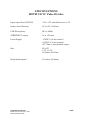
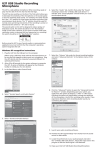
MOTM-730 VC Pulse Divider
Owner’s Manual
Synthesis Technology
6625 Quail Ridge Dr.
Fort Worth, TX 76180
(817) 281-7776
www.synthtech.com
Feb. 8, 2009
GENERAL INFORMATION
The MOTM-730 is a PIC microprocessor-based digital module that takes an input
signal and generates lower frequency square waves at multiples of the input frequency.
It is a “big brother” to the MOTM-120 Sub-Octave Mux (in divide mode): the ‘120
divides by the multiples 2, 4, 8 and 16. The MOTM-730 can generate multiples from 1
to 33, as well as ‘half’ multiples (1.5 to 16.5). There is also an 8-step, positive-going
sawtooth wave that has 3 user-selectable step intervals.
The ‘730 requires a 6-pin, +5V, +-15V power interface (such as a MOTM-950). There
are no internal calibrations required for this module.
FRONT PANEL CONTROLS/INPUTS
Refer to the following illustration for the various functions and controls of the MOTM730.
SYNTHESIS TECHNOLOGY
MOTM-730 User Guide Feb. 8, 2009
WWW.SYNTHTECH.COM
PAGE 2
LED DISPLAY
When the MOTM-730 is first powered up, the display will show 730 for a few seconds,
then indicate the divisor for the divide-by-N (/N) output. In the example, the divisor is
set to divide-by-25.
MODE SWITCHES
The 4 toggle switches can be used at any time to set the overall operation of the
module. They are as follows:
EDGE – sets which clock edge of the input clock the divider will trigger. POS is
positive edge, NEG is negative edge.
DIVIDER – sets either FULL divider ratios (2, 3, 4…33) or HALF ratio (1.0, 1.5, 2.0,
2.5, …16.5) for both the /N output AND all the fixed ratio dividers. What this means is
that the front panel silkscreen for the fixed divider outputs is correct if this switch is in
the FULL position. In the HALF position, all of the fixed dividers are then divided by
2. For example, the /5 output becomes /2.5.
STEP CLK – selects what the STEPPED sawtooth waveform/CV increments by. In the
CLK IN position, the internal counter increments one step for each input clock cycle. In
the /N position, the internal counter increments each time the /N output cycles.
INTERVAL – selects the voltage interval (step size) of the STEPPED output. The
sawtooth is generated by a 3-bit up-counter driving a 3-bit DAC. The DAC has 3 output
gain settings: 4ths, 5ths and octaves. Note that this DAC is +-2% accurate and cannot
be calibrated exactly.
PANEL CONTROLS
INIT DIV – Initial Divisor ratio, for the /N output. Does not affect the fixed divide
outputs.
DIV MOD – attenuator for a CV applied to the DIV MOD jack.
INPUT/OUTPUT JACKS
CLK IN – the CLOCK INPUT. The input clock can by any signal, from DC to 16KHz,
with a range of -5V to +5V. Internally, there is a fast comparator with a +1V threshold.
Any voltage below 1V is seen as a ‘0’ (no input) and a voltage above +1V is a ‘1’, or a
positive input. The transition from 0 to 1 is called a clock edge, and the ‘730 counts
every edge it sees and controls the divisor outputs accordingly.
SYNTHESIS TECHNOLOGY
MOTM-730 User Guide Feb. 8, 2009
WWW.SYNTHTECH.COM
PAGE 3
It is important to understand how this works, as it allows many input signals to be
used to generate the outputs. In many patches, the outputs are NOT audio, but
gates/triggers to envelope generators, drum machines or other devices.
Also, the input waveform does NOT have to be a pulse/square wave. You can use sines,
triangles, sawtooths, envelopes, gates, triggers, amplified audio or just about anything
as long as the signal crosses the +1V threshold. You will find, however, that the most
stable/predictable outputs are generated when a square or pulse is used as CLK IN
(say, from a MOTM VCO or LFO).
When using amplified audio, you may find adding a DC offset (a MOTM-830 is perfect
for this) to the signal will reduce “chattering” as the audio swings up/down across the
1V threshold. Then again, some of you will prefer this.
RUN/STOP – in normal use, the module is set to always RUN and no patch cord is
needed. In RUN mode, the LED display will show the divisor for the /N output.
In order to STOP the module, and set all outputs to 0V, you apply a signal to the
RUN/STOP jack that is less than +1V (ground is a handy signal for this). The display
will then show the following:
And all outputs will stop counting. The module remains in this mode until the signal
exceeds +1V.
DIV MOD - -5V to +5V control voltage input range. This voltage, after attenuated by
the DIV MOD panel control, is added to the setting of INIT DIV.
If the control voltage is negative, this will reduce the initial divisor.
If the control voltage is positive, it will increase the initial divisor.
You can apply any CV to this jack (as long as it is within spec): keyboard CV,
envelopes, LFOs, random voltages from a S&H, etc.
The circuitry has “hard limits” on the upper and lower divisor voltages the PIC
processor sees. Therefore, it is possible to ‘rail’ the voltage at either end. This will not
harm the module. The input CV is set so that a -2.5V to +2.5V signal sweeps the range
SYNTHESIS TECHNOLOGY
MOTM-730 User Guide Feb. 8, 2009
WWW.SYNTHTECH.COM
PAGE 4
from minimum to maximum if the INIT DIV knob is in the middle of rotation. If you
use the direct output of a MOTM VCO/LFO (+-5V), you will have to set the DIV MOD
at center rotation to get the full sweeping effect (remember, the voltage adds to the
initial setting).
DIVISOR OUTPUTS
Each divisor output runs independent of the others. The only thing in common is:
-
All use the same input clock, and the same edge as set by the switch
All outputs are 0V to +5V square waves (not AC coupled, but DC coupled)
All respond to RUN/STOP
The outputs are driven by 74HC244 line driver ICs with a 100ohm series resistance.
The outputs are done in this manner to easily trigger/gate MOTM-800 envelope
generators and control MOTM-190 VCAs. You can also treat the outputs as audio, but
before sending these signals to a mixer/amplifier, you need to pass them through an AC
coupled module first (like a VCF, or the upper channel of a MOTM-190).
/N – this output will follow the setting shown in the LED display, as set by the addition
of the front panel setting and any applied control voltage.
Fixed divisors – remember, the silkscreen on the panel is for the FULL setting!
Switching to HALF means the outputs speed up by 2X (because the ratio is ½ of the
printed setting).
STEPPED OUTPUT
This output is a positive-going (starting at 0 volts and incrementing upward), 8-step,
sawtooth waveform. There is 1 step at 0V, and 7 successive steps of positive voltages.
The amount of each step is set by the panel switch (as ‘heard’ by applying this output
to a VCO). The voltage is fairly accurate, but not really accurate. If you want to ‘tune
in’ a more precise interval, use the OCT (octave) range (1V/step) and apply this to the
FM IN of a VCO. Then, you can ‘dial in’ what the interval is. This was just a fun, cheap
added output. Use it to drive VCOs, VCFs or any other module. You can use it for
audio, too (has a nice raspy tone).
SYNTHESIS TECHNOLOGY
MOTM-730 User Guide Feb. 8, 2009
WWW.SYNTHTECH.COM
PAGE 5
USING THE MOTM-730
a) apply a square/pulse from a LFO to CLK IN. Patch the STEPPED CV to a VCO
and listen to the 8-note sequences
b) Use individual divisor outputs patched to the GATE of MOTM-800 EGs. I call
this a ‘timbral sequencer’, because now you can control when different voices are
triggered based on the divisors used.
c) Use a MOTM VCO, set fairly high in initial frequency, as CLK IN. Use different
combinations of divisors into a MOTM-830 mixer. Now you have a cheesy
Hammond organ drawbar set (err…drawknob set??!?).
d) Use the output of a MOTM-101 S&H to the DIV MOD CV. This will set up
random divisors on the /N, which in turn can then randomly trigger events. You
can adjust the DIV MOD pot to set the ‘uncertainty probability’ of the event.
e) Think of feedback patches based on the STEPPED output. This CV is like a
tachometer: the frequency is 1/8th of the selected clock AND there a CVs that
increments. Hmmm…what if the STEPPED output modulated a VCO that was
connected to CLK IN?
Thanks for purchasing the MOTM-730 (even if it was off eBay or another user). If you
sit back and think a bit, you will discover many interesting applications for this
module.
SYNTHESIS TECHNOLOGY
MOTM-730 User Guide Feb. 8, 2009
WWW.SYNTHTECH.COM
PAGE 6
SPECIFICATIONS
MOTM-730 VC Pulse Divider
Input signal level (CLK IN)
-5V to +5V, threshold set at +1.0V
Output level (divisors)
0V to +5V, 100ohms
CLK IN frequency
DC to 16Khz
STEPPED CV output
0v to +8V max
Power Supply
-15VDC @ 14 ma nominal
+15VDC @ 16 ma nominal
+5V 75ma + 4ma/patched output
Size
2U x 5U
3.72” x 8.72”
88.2mm x 221.5mm
Depth behind panel
2.0 inches (50.8mm)
SYNTHESIS TECHNOLOGY
MOTM-730 User Guide Feb. 8, 2009
WWW.SYNTHTECH.COM
PAGE 7