1
BusWorks Model XT1543-000
8 CH Voltage Output + 4 CH Digital I/O w/USB & Profinet
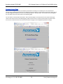
I/O Config/Test…
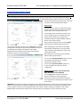
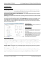
Input/Output Configure…
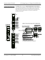
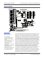
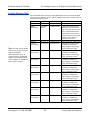
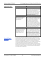
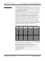
Invert Input Logic: Note that this model has active-high inputs, but you can choose to apply an inverter to your input
channel by selecting “Yes” here. This only applies to input logic of this model, not its output control logic, as setting an
output to “1” always turns it ON for this model regardless of this option setting.
Support Coil Versus Holding Registers for Digital Output Writes: This is a Modbus TCP/IP option and it has no effect for
Ethernet/IP or Profinet models.
Status field: This field displays status messages relative to sending and receiving I/O parameters over USB to the module.
[Send Config] Button: Click this button to send the entire I/O configuration to the device. You can choose to do this one
time after you have setup all the I/O channels individually.
Once you have made your configuration selections, click the [Send Config] button to write them to the module. You can
read the USB Status of your sent configuration message to the unit in the “Status” field just above the [Send Config]
button. Alternately, you could click “File” in the upper left hand corner of the screen to save the settings you made to a
file on your PC, for later reference.
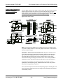
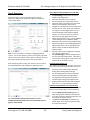
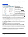
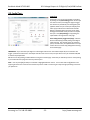
Input/Output Test
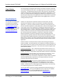
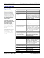
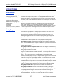
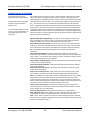
You can use this screen to test the operation of your
analog and digital outputs.
Analog Output Test
There are 8 or 4 analog output fields that allow you
to enter or read output values in volts (XT154x) or
mA (XT153x).
[Read Analog Output]: Click this button to read the
current analog output values into the channel fields.
[Write Analog Outputs]: Click this button to write
the analog output values that you typed into the
channel fields to the output channels.
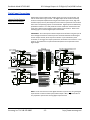
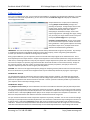
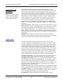
Digital Input & Output Test
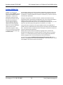
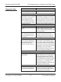
In addition to testing the analog outputs, you can turn digital outputs On/Off by clicking the [Channel] toggle button.
Optionally, you can click the [Start Polling] button to trigger the software to periodically read the digital inputs (it updates
about once per second) and display their states via the simulated LED’s. Note the simulated lamp next to the [Start
Polling] button flashes slowly each time it samples the digital input. Click [Stop Polling] to stop polling the inputs before
moving onto the next page.
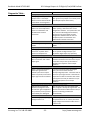
[Channel…] Button: Click this button to turn the associated output ON. Note that turning it ON connects the output to
the digital excitation source (high-side switch). A “1” is superimposed on the lamp for ON, and “0” for OFF (true
regardless of the Invert Input logic Setting).
[Start Polling] Button: This toggles between Start/Stop. Click this button to Start/Stop periodic polling of the input
channels. The small green simulated lamp next to this button will flash each time a new sample is taken (channel states
are indicated and updated about once per second). Be sure to first stop polling before moving onto another page.
Status: This field displays status messages relative to sending and receiving channel I/O over USB to the module.
Acromag, Inc. Tel: 248-295-0880
- 22 -- 22 -
http://www.acromag.com
http://www.acromag.com