1
SurgiVet® V6004
NIBP Monitor
Operation Manual
B e
f n
h
a Z
x
i
d
- English
Catalog Number V1876
Version 8, February 2008
© 2008 Smiths Medical family of companies. All rights reserved.
o
Table of Contents
Table of Contents
Warranty and Service Information.......................................................................................... v
Proprietary Notice.....................................................................................................................................................................................v
Warranty.......................................................................................................................................................................................................v
Limited Warranty...............................................................................................................................................................................v
Loaner Device (Domestic Sales Only).......................................................................................................................................vi
Disclaimer of Warranties................................................................................................................................................................vi
Conditions of Warranty..................................................................................................................................................................vi
Limitation of Remedies..................................................................................................................................................................vi
Warranty Procedure................................................................................................................................................................................vii
Chapter 1: Introduction........................................................................................................ 1-1
About this Manual.................................................................................................................................................................................1-1
Definition of Symbols..........................................................................................................................................................................1-1
General Warnings..................................................................................................................................................................................1-3
NIBP Warnings........................................................................................................................................................................................1-5
Oximetry Warnings...............................................................................................................................................................................1-5
General Cautions...................................................................................................................................................................................1-6
NIBP Cautions.........................................................................................................................................................................................1-7
General Notes.........................................................................................................................................................................................1-7
Chapter 2: Intended Use and General Information............................................................ 2-1
Intended Use...........................................................................................................................................................................................2-1
General Description..............................................................................................................................................................................2-1
Front Panel...............................................................................................................................................................................................2-2
Display.......................................................................................................................................................................................................2-3
Side Panel.................................................................................................................................................................................................2-3
Keys.............................................................................................................................................................................................................2-4
Rear Panel.................................................................................................................................................................................................2-5
Chapter 3: Setting Up the Monitor....................................................................................... 3-1
Unpacking the Monitor and Checking the Shipment..............................................................................................................3-1
Turning Alarm and Alert Tones On and Off..................................................................................................................................3-1
Working With System-Wide Settings..............................................................................................................................................3-1
Setting the Time or Date............................................................................................................................................................3-2
Optional Printer.............................................................................................................................................................................3-2
AC Power..................................................................................................................................................................................................3-2
Chapter 4: Alarms and Alerts................................................................................................ 4-1
Alarms........................................................................................................................................................................................................4-1
Manually Reset NIBP Alarms.....................................................................................................................................................4-1
Alerts..........................................................................................................................................................................................................4-2
Adjusting or Viewing Alarm Limits..................................................................................................................................................4-2
Alarm and Alert Tones..........................................................................................................................................................................4-3
V6004 Operation Manual
Table of Contents
Turning Alarm and Alert Tones On and Off.........................................................................................................................4-3
System Alert Condition: Low Battery.....................................................................................................................................4-3
Audible and Visual Indicators............................................................................................................................................................4-4
Chapter 5: NIBP...................................................................................................................... 5-1
Theory of Operation.............................................................................................................................................................................5-1
Using the NIBP Parameter..................................................................................................................................................................5-1
Connecting the Cuff and Hose.........................................................................................................................................................5-1
Suggested Application Sites.....................................................................................................................................................5-2
Connect the Cuff and Hose.......................................................................................................................................................5-2
Verifying the Initial Cuff Inflation Pressure...................................................................................................................................5-3
Taking NIBP Measurements...............................................................................................................................................................5-3
Manual NIBP Measurement......................................................................................................................................................5-3
Automatic NIBP Measurement.................................................................................................................................................5-4
Stat NIBP Measurement..............................................................................................................................................................5-4
Canceling NIBP Measurements........................................................................................................................................................5-4
Changing the Auto NIBP Measurement Interval........................................................................................................................5-5
NIBP Alerts and Status Messages.....................................................................................................................................................5-6
Status Messages............................................................................................................................................................................5-6
Application Note: NIBP Cuff Inflation Method............................................................................................................................5-6
Chapter 6: Using the Oximeter Option................................................................................ 6-1
General Description..............................................................................................................................................................................6-1
Pulse Oximetry Theory of Operation..............................................................................................................................................6-1
Disabling the Oximetry Option........................................................................................................................................................6-2
Adjusting the Pulse Beep Volume...................................................................................................................................................6-2
Attaching the Patient – Oximetry....................................................................................................................................................6-2
Choosing the Sensor...................................................................................................................................................................6-3
Clean or Disinfect the Sensors.................................................................................................................................................6-3
Checking the Sensor and Oximetry Cable...........................................................................................................................6-3
Attach the Sensor to the Patient......................................................................................................................................................6-4
Application Guide.................................................................................................................................................................................6-5
Universal ‘Y’ (Lingual) Sensor.............................................................................................................................................................6-5
Mini Clip...........................................................................................................................................................................................6-5
Universal ‘C’ sensor.......................................................................................................................................................................6-6
Reflectance Sensor.......................................................................................................................................................................6-6
Pulse Oximeter Sensor Application Tips.......................................................................................................................................6-7
Testing Sensor Function......................................................................................................................................................................6-7
Primary Applications for Sensors.....................................................................................................................................................6-8
Lingual Sensor (Lingual and Mini Clip).................................................................................................................................6-8
C Sensor............................................................................................................................................................................................6-8
Reflectance Sensor.......................................................................................................................................................................6-8
Limitations...............................................................................................................................................................................................6-8
Checking the Oximeter’s Performance..........................................................................................................................................6-8
ii
V6004 Operation Manual
Table of Contents
Chapter 7: Trends................................................................................................................... 7-1
Trend Storage..........................................................................................................................................................................................7-1
Recall Mode.............................................................................................................................................................................................7-1
Time Stamps............................................................................................................................................................................................7-1
Trend Display..........................................................................................................................................................................................7-2
Trend Printout.........................................................................................................................................................................................7-2
Clearing Trends.......................................................................................................................................................................................7-2
Chapter 8: Serial Output/Printer.......................................................................................... 8-1
Serial Output Requirements..............................................................................................................................................................8-1
Data Logging Mode..............................................................................................................................................................................8-1
Chapter 9: Routine Maintenance.......................................................................................... 9-1
Charging the Battery............................................................................................................................................................................9-1
Cleaning and Disinfecting..................................................................................................................................................................9-1
Maintenance Chart...............................................................................................................................................................................9-2
Long Term Storage................................................................................................................................................................................9-2
Chapter 10: Troubleshooting..............................................................................................10-1
Chapter 11: Optional Supplies and Accessories................................................................11-1
Ordering Information........................................................................................................................................................................ 11-1
Chapter 12: Specifications..................................................................................................12-1
NIBP......................................................................................................................................................................................................... 12-1
SpO2. ....................................................................................................................................................................................................... 12-1
Pulse Rate.............................................................................................................................................................................................. 12-2
Pulse Strength..................................................................................................................................................................................... 12-2
Audible Alarms.................................................................................................................................................................................... 12-2
Alarm Limit Ranges............................................................................................................................................................................ 12-2
Serial Output........................................................................................................................................................................................ 12-2
Power...................................................................................................................................................................................................... 12-2
Physical................................................................................................................................................................................................... 12-3
Environment......................................................................................................................................................................................... 12-3
Equipment Classification................................................................................................................................................................. 12-3
Appendix A: Guidance and Manufacturer’s Declaration...................................................A-1
Guidance and Manufacturer’s Declaration - IEC 60601-1-2 Requirements..................................................................... A-1
Electromagnetic Emissions - Emissions Test...................................................................................................................... A-1
Electromagnetic Emissions – Immunity.............................................................................................................................. A-2
Recommended Separation Distances........................................................................................................................................... A-4
Appendix B: Revision History...............................................................................................B-1
V6004 Operation Manual
iii
Table of Contents
The serial autocorrelation technology in the monitor is covered by U.S. Patent No. 5,558,096.
SurgiVet and the Smiths design mark are trademarks of the Smiths Medical family of companies. The symbol
® indicates the trademark is registered in the U.S. Patent and Trademark Office and certain other countries. All
other names and marks mentioned are the trade names, trademarks or service marks of their respective owners.
iv
V6004 Operation Manual
Warranty and Service Information
Warranty and Service Information
Proprietary Notice
Information contained in this document is copyrighted by Smiths Medical PM, Inc. and may not be duplicated in
full or part by any person without prior written approval of Smiths Medical PM, Inc. Its purpose is to provide the
user with adequately detailed documentation to efficiently install, operate, maintain and order spare parts for
the device supplied. All information contained in this document is believed to be current and accurate as of the
date of publication or revision, but does not constitute a warranty.
Warranty
Limited Warranty
Smiths Medical PM, Inc. (“Seller”) warrants to the original purchaser that the Product, not including applicable
accessories, shall be free from defects in material and workmanship under normal use, if used in accordance with
its labeling, for two years from the date of shipment to the original purchaser.
Seller warrants to the original purchaser that the reusable oximeter sensors supplied as accessories, shall be free
from defects in materials and workmanship under normal use, if used in accordance with its labeling, for one
year from the date of shipment to the original purchaser (USA only).
Seller warrants to the original purchaser that the AC Power supply/charger supplied, with the exception of part
number 3005, shall be free from defects in materials and workmanship under normal use, if used in accordance
with its labeling, for 1 year from the date of shipment to the original purchaser (USA only).
Seller warrants to the original purchaser that the reusable temperature cable supplied as accessories shall be
free from defects in materials and workmanship under normal use, if used in accordance with its labeling, for 6
months from the date of shipment to the original purchaser (USA only).
Seller warrants to the original purchaser that the reusable ECG leads, reusable invasive pressure cable, reusable
NIBP purple hose, disposable temperature probe, disposable invasive pressure transducer and disposable
sample lines supplied as accessories, shall be free from defects in materials and workmanship under normal use,
if used in accordance with its labeling, for 90 days from the date of shipment to the original purchaser (USA only).
Blood pressure cuffs carry a (6) six month warranty, pending evaluation by Smiths Medical PM, Inc. (SMPM)
Technical Services. Cuffs that are contaminated, have liquid in them, have been misused/abused or are older
than (6) months will not be covered under warranty. The sole obligation of SMPM under this warranty will be to
repair or replace, at its option, products that prove to be defective during the warranty period.
The foregoing shall be the sole warranty remedy. Except as set forth herein, seller makes no warranties, either
expressed or implied, including the implied warranties of merchantability and fitness for a particular purpose. No
warranty is provided if the products are modified without the express written consent of Smiths Medical Pm, Inc.
and seller shall not be liable in any event for incidental or consequential damage. This warranty is not assignable.
Warranties are subject to change. Please contact Smiths Medical PM Inc. for current warranty information.
V6004 Operation Manual
Warranty and Service Information
Loaner Device (Domestic Sales Only)
Smiths Medical PM, Inc. (SMPM) will, for the period of warranty, make loaner devices available at no charge
(domestic sales only) if, in the opinion of SMPM, the repair of the customer’s device would require an
unreasonable period of time to repair, and there is a suitable loaner available during the time of the repair.
SMPM may make available a loaner device, for a fee, should it be requested while an out of warranty device is in
for service.
Disclaimer of Warranties
THE FOREGOING EXPRESS WARRANTY, AS CONDITIONED AND LIMITED, IS IN LIEU OF AND EXCLUDES ALL
OTHER WARRANTIES WHETHER EXPRESS OR IMPLIED, BY OPERATION OF LAW OR OTHERWISE, INCLUDING
BUT NOT LIMITED TO, ANY IMPLIED WARRANTIES OF MERCHANTABILITY OR FITNESS FOR A PARTICULAR
PURPOSE.
Seller disclaims responsibility for the suitability of the Product for any particular medical treatment or for any
medical complications resulting from the use of the Product. This disclaimer is dictated by the many elements
which are beyond Seller’s control, such as diagnosis or patient, conditions under which the Product may be used,
handling of the Product after it leaves Seller’s possession, execution of recommended instructions for use and
others.
Conditions of Warranty
This warranty is void if the Product has been altered, misused, damaged by neglect or accident, not properly
maintained or recharged, or repaired by persons not authorized by Seller. Misuse includes, but is not limited to,
use not in compliance with the labeling or use with accessories not manufactured by Seller. This warranty does
not cover normal wear and tear and maintenance items.
Limitation of Remedies
The original purchaser’s exclusive remedy shall be, at Seller’s sole option, the repair or replacement of the
Product. THIS IS THE EXCLUSIVE REMEDY. In no event will Seller’s liability arising out of any cause
whatsoever (whether such cause is based in contract, negligence, strict liability, tort or otherwise) exceed
the price of the Product and in no event shall Seller be responsible for consequential, incidental, or
special damages of any kind or nature whatsoever, including by not limited to, lost business, revenues
and profits.
vi
V6004 Operation Manual
Warranty and Service Information
Warranty Procedure
To obtain warranty service or repair of SurgiVet® equipment in the USA, please contact Veterinary Clinical
Support to obtain a Return Authorization Number. Please provide the serial number of all equipment that will be
returned. Any equipment returned for evaluation must be cleaned and decontaminated prior to being handled
by our service technicians. For cleaning instructions, please refer to the appropriate section in the operation
manual. If equipment is returned prior to cleaning, and in our opinion it represents a potential biological hazard,
the equipment will be returned to the sender as is.
Reference the return authorization number when returning your Product, freight and insurance prepaid by
Purchaser, to:
Smiths Medical PM, Inc.
Attn: Repairs / return #
N7W22025 Johnson Drive
Waukesha, WI 53186
Veterinary Clinical Support
Telephone: 1-262-513-8500
Toll-Free: 1-888-745-6562 (USA only)
Fax:
1-262-513-9069
Web: www.surgivet.com
Seller will not be responsible for unauthorized returns or for loss or damage to the Product during the return
shipment. The repaired or replaced Product will be shipped, freight prepaid by Seller, to Purchaser.
To obtain warranty information outside the USA, contact your local distributor.
NOTE! Shipments received without a return number will be returned to sender.
Keep all original packing material, including foam inserts. If you need to ship the device, use only the original
packaging material, including inserts. Box and inserts should be in original condition. If original shipping
material in good condition is not available, it should be purchased from Smiths Medical PM, Inc.
Damages occurred in transit in other than original shipping containers are the responsibility of the shipper. All
costs incurred returning devices for repair are the responsibility of the shipper.
V6004 Operation Manual
vii
Warranty and Service Information
This page is intentionally left blank.
viii
V6004 Operation Manual
Chapter 1: Introduction
Chapter 1: Introduction
About this Manual
The Operation Manual provides installation, operation, and maintenance instructions for the veterinary
professional trained in monitoring cardiovascular activity.
Definition of Symbols
symbol
x
h
B
e
i
n o
d
a
Z
F
definition
On/Off
NIBP Start
Alarm Silence
Cancel
Stat
Up and Down Arrows
Manual/Auto
Recall
Alarm Set
Printer Output or Print Key
Print feed
g
c
Alarm silence LED
M
Low battery LED
High Priority Alarm (red) or Low Priority Alarm/Alert (yellow) LED
Small animal patient mode LED
f
Interval
SYS
Systolic blood pressure
DIA
Diastolic blood pressure
MAP
Mean arterial pressure
p
Pulse Rate LED (beats per minute)
%SpO2
Percent Oxygen Saturation
V6004 Operation Manual
1-1
Chapter 1: Introduction
symbol
definition
6
Federal (U.S.A.) law restricts this device to sale by or on the order of a veterinarian.
p
Type CF equipment
q
Defibrillator-proof type CF equipment.
g
Attention, see instructions for use.
7
D
E
Refer servicing to qualified service personnel.
y
<
>
Date of Manufacture
K
Moisture Sensitive
IPX1
1
G
0
Z
Collect
Separately
Y
Output Voltage
Input Voltage
Catalog Number
Serial Number
Drip Proof (monitor only)
Non AP Device
Direct Current
Loudspeaker
Disposal (EU Countries)
Under the Waste Electrical and Electronic Equipment (WEEE) Directive 2006/96/EC and
implementing regulations, all devices and service items within the scope of the Directive
purchased new after August 13, 2005 must be sent for recycling when ultimately becoming
waste. Devices and items must not be disposed of with general waste.
If purchased before that date, they may also be sent for recycling if being replaced on a onefor-one, like-for-like basis (this varies depending on the country). Recycling instructions to
customers using Smiths Medical products are published on the internet at:
http://www.smiths-medical.com/recycle
Disposal (other countries)
When disposing of this device, its batteries or any of its accessories, ensure that any negative
impact on the environment is minimized. Contact your local waste disposal service and
use local recycling or disposal schemes. Separate any other parts of the equipment where
arrangements can be made for their recovery, either by recycling or energy recovery. The
main batteries are potentially harmful and will require separate disposal according to
manufacturer’s instructions or local regulations.
Note: If applicable, EU, national or local regulations concerning
waste disposal must take precedence over the above advice.
1-2
V6004 Operation Manual
Chapter 1: Introduction
keyword
definition
WARNING!
Tells you about something that could hurt the patient or hurt the operator.
CAUTION!
Tells you about something that could damage the monitor.
NOTE!
Tells you other important information.
General Warnings
WARNING! This product is intended for veterinary use only.
WARNING! Do not use this device in the presence of flammable anesthetics.
WARNING! ELECTRICAL SHOCK HAZARD when cover is removed. Do not remove covers. Refer servicing
to qualified personnel.
WARNING! Do not use this device in the presence of magnetic resonance imaging (MR or MRI)
equipment.
WARNING! Operation of this device may be adversely affected in the presence of computed tomograph
(CT) equipment.
WARNING! Operation of this device may be adversely affected in the presence of conducted transients
or strong electromagnetic (EM) or radiofrequency (RF) sources, such as electrosurgery and
electrocautery equipment, x-rays, and high intensity infrared radiation.
WARNING! Do not plug the monitor into an outlet controlled by a wall switch.
WARNING! This device is intended for use by persons trained in veterinary health care. The operator
must be thoroughly familiar with the information in this manual before using the monitor.
WARNING! This device must be used in conjunction with clinical signs and symptoms. This device is only
intended to be an adjunct in patient assessment.
WARNING! If the accuracy of any measurement is in question, check the patient’s vital sign(s) by an
alternative method and then check the monitor for proper functioning.
WARNING! The monitor should not be used in the presence of electrosurgical equipment. The device has
no protective mechanisms to prevent patient burns when used with high frequency surgical
equipment.
WARNING! Equipment is protected against defibrillator discharge. Rate meters and displays may be
temporarily affected during defibrillation, but will rapidly recover.
V6004 Operation Manual
1-3
Chapter 1: Introduction
WARNING! The vital signs monitor is suitable for use within the patient environment IEC 60950 approved
equipment must be placed outside of the patient environment. The patient environment is
defined as any volume in which intentional or unintentional contact can occur between the
patient and parts of the system or between the patient and other persons touching parts of
the system.
Figure 1.1: Patient Environment (Dimensions are not prescriptive)
WARNING! When connecting this monitor to any instrument, verify proper operation before clinical use.
Refer to the instrument’s user manual for full instructions. Accessory equipment connected
to the monitor’s data interface must be certified according to the respective IEC standards,
i.e., IEC 950 for data-processing equipment or IEC 601-1 for electromedical equipment. All
combinations of equipment must be in compliance with IEC 601-1-1 systems requirements.
Anyone connecting additional equipment to the signal input port or signal output port
configures a medical system, and, therefore, is responsible that the system complies with the
requirements of the system standard IEC 601-1-1.
WARNING! Any monitor that has been dropped or damaged should be checked by qualified service
personnel to insure proper operation prior to use.
WARNING! This monitor will not operate effectively on patients who are experiencing convulsions or
tremors.
WARNING! Patient safety can be compromised by the use of a power supply not supplied by Smiths
Medical PM, Inc. Use only the power supply included with your monitor, or one approved by
Smiths Medical PM, Inc.
WARNING! Disconnect the AC power supply from the outlet before disconnecting it from the monitor.
Leaving the AC power supply connected to an AC power outlet without being connected to
the monitor may result in a safety hazard.
WARNING! Do not allow any moisture to touch the AC power supply connectors or a safety hazard may
result. Ensure that hands are thoroughly dry before handling the AC power supply.
WARNING! Do not place the monitor in the patient’s bed. Do not place the monitor on the floor.
WARNING! Failure to place the monitor away from the patient may allow the patient to turn off, reset, or
damage the monitor, possibly resulting in the patient not being monitored. Make sure the
patient cannot reach the monitor.
WARNING! Failure to carefully route the cable from the sensor to the monitor may allow the patient to
become entangled in the cable, possibly resulting in patient strangulation. Route the cable
in a way that will prevent the patient from becoming entangled in the cable. If necessary, use
tape to secure the cable.
Warning! If there is a risk of the AC power supply becoming disconnected from the monitor during use,
secure the cord to the monitor several inches from the connection.
1-4
V6004 Operation Manual
Chapter 1: Introduction
WARNING! Medical electrical equipment, including this device, needs special precautions regarding
electro-magnetic compatibility (EMC) and needs to be installed and put into service
according to the EMC information provided in this manual.
WARNING! The monitor should not be used adjacent to or stacked with other equipment. If adjacent or
stacked use is necessary, the monitor should be observed to verify normal operation in the
configuration in which it will be used.
WARNING! Use only original manufacturer or recommended patient cables. Use of accessories other
than those specified may result in increased electro-magnetic (EM) emissions or decreased
EM immunity of the device. To avoid potential electro-static discharge interference, do not
use cables which incorporate metal or metal-coated connectors.
WARNING! It is the operator’s responsibility to set alarm limits appropriately for each individual patient.
Warning! Verify that all LEDs (light emitting diodes) on the display light up upon startup of the device.
NIBP Warnings
WARNING! Readings may be difficult to obtain in animals smaller than five (5) pounds.
WARNING! Blood pressure measurements may be inaccurate if cuffs and/or hoses are used other than
those specified by Smiths Medical PM, Inc. (Veterinary).
WARNING! Make sure that hoses are not kinked, compressed, or restricted.
WARNING! Check that operation of the equipment does not impair the circulation of the monitored
patient.
WARNING! Repeated use of the stat mode for periods longer than 15 minutes should be avoided
to reduce the patient’s risk for soft tissue or nerve damage. When using the monitor for
long periods of time, select the longest clinically appropriate measurement interval and
periodically examine the patient for signs of injury and ensure proper cuff placement.
WARNING! Blood pressure measurements may not be accurate for patients experiencing moderate to
severe arrhythmias.
Oximetry Warnings
WARNING! Use only SpO2 sensors supplied with, or specifically intended for use with, this device.
WARNING! Incorrectly applied sensors may give inaccurate readings. Refer to the sensor insert for
proper application instructions.
WARNING! Prolonged use or the patient’s condition may require changing the sensor site periodically.
Change sensor site and check skin integrity, circulatory status, and correct alignment at least
every 4 hours.
WARNING! When attaching SpO2 sensors with Microfoam® tape, do not stretch the tape or attach the
tape too tightly. Tape applied too tightly may cause inaccurate readings and blisters on the
animal’s skin (lack of skin respiration, not heat, causes the blisters).
V6004 Operation Manual
1-5
Chapter 1: Introduction
WARNING! Dyes introduced into the bloodstream, such as methylene blue, indocyanine green, indigo
carmine, patent blue V (PBV), and fluorescein, may adversely affect the accuracy of the SpO2
reading.
WARNING! Any condition that restricts blood flow, such as use of a blood pressure cuff or extremes in
systemic vascular resistance, may cause an inability to determine accurate pulse and SpO2
readings.
WARNING! Significant levels of dysfunctional hemoglobins, such as carboxyhemoglobin (with COpoisoning) or methemoglobin (with sulfonamide therapy), will adversely affect the accuracy
of the SpO2 measurement.
WARNING! SpO2 measurements may be adversely affected in the presence of high ambient light. If
necessary, shield the sensor area (with a surgical towel, for example).
WARNING! Dark skin tone or fur pigment may cause an inability to determine accurate pule rates and
SpO2 readings. Seeking the most appropriate site for sensor placement is advisable.
WARNING! Optical cross-talk can occur when two or more sensors are placed in close proximity. It can be
eliminated by covering each site with an opaque material.
WARNING! Under certain clinical conditions, pulse oximeters may display dashes if unable to display
SpO2 and/or pulse rate values. Under these conditions, pulse oximeters may also display
erroneous values. These conditions include, but are not limited to: patient motion, low
perfusion, cardiac arrhythmias, high or low pulse rates, or a combination of the above
conditions. Failure of the clinician to recognize the effects of these conditions on pulse
oximeter readings may result in patient injury.
General Cautions
CAUTION! Ensure the device’s AC rating is correct for the AC voltage at your installation site before using
the monitor. The monitor’s AC rating is shown on the external power supply. If the rating is not
correct, do not use the monitor; contact Smiths Medical PM, Inc. Veterinary Clinical Support
for help.
CAUTION! Do not allow water or any other liquid to spill onto the monitor. Evidence that liquid has been
allowed to enter the monitor voids the warranty.
CAUTION! Unplug the external power supply from the monitor before cleaning or disinfecting the
monitor.
CAUTION! Chemicals used in some cleaning agents may cause brittleness of plastic parts. Follow
cleaning instructions in this manual.
CAUTION! Should the device become wet, wipe off all moisture and allow sufficient time for drying
before operating. For devices with the optional electronic thermometer or printer, servicing is
required for proper function after accidental wetting.
CAUTION! Pressing front panel keys with sharp or pointed instruments may permanently damage the
keypad. Press front panel keys only with your finger.
CAUTION! Do not disassemble the unit. The unit is not user serviceable.
personnel.
7 Refer to qualified service
CAUTION! Operation of this device may be adversely affected in the presence of portable and mobile
communications equipment.
1-6
V6004 Operation Manual
Chapter 1: Introduction
NIBP Cautions
CAUTION! Verify the proper cuff size before each measurement.
CAUTION! Extremity and cuff motion should be minimized during blood pressure determinations.
CAUTION! Proper blood pressure cuff size and placement are essential to the accuracy of the blood
pressure determination.
CAUTION! Any blood pressure recording can be affected by the position of the patient, his or her
physiologic condition, and other factors.
CAUTION! Blood pressure measurements should be interpreted by a veterinarian.
General Notes
NOTE! All user and patient accessible materials are non-toxic.
NOTE! The equipment is suitable for connection to public mains.
NOTE! To tear paper off gently, pull paper towards you tightly against the cutter and use the cutter to
tear it off. Use caution not to pull paper through the printer as this might damage the paper feed
rollers.
NOTE! Connect the AC Charger to the AC Power Connector of the monitor first and the AC Charger to the
Wall Outlet second.
NOTE! Alarm limits are retained during power cycles, except for the following note.
NOTE! If the low alarm limit for SpO2 is set to a value lower than 80 when the monitor is powered down,
then this low alarm limit will be reset to 80 at power up.
NIBP Notes
NOTE! Systolic and Diastolic blood pressure measurements determined with this device are equivalent
to those obtained by a trained observer using the cuff/stethoscope auscultation method,
within the limits prescribed by the American National Standard, Electronic or Automated
Sphygmomanometers. AAMI SP10-1992.
NOTE! Mean Arterial blood pressure measurements determined with this device are equivalent to those
obtained by an intra-arterial blood pressure measurement device as determined by Smiths
Medical PM, Inc.
V6004 Operation Manual
1-7
Chapter 1: Introduction
This page is intentionally left blank.
1-8
V6004 Operation Manual
Chapter 2: Intended Use and General Information
Chapter 2: Intended Use and General Information
Intended Use
The V6004 monitor is a non-invasive blood pressure monitor with optional SpO2 and printer. It is intended for
spot checking or monitoring a patient’s systolic, diastolic, and mean arterial pressure (MAP), pulse rate, and SpO2
with the oximetry option. The NIBP monitor may be used in the hospital or clinical environment. The oximetry
option works with all SurgiVet® oximetry sensors, providing SpO2 and pulse rate on all patients. The V6004
monitor permits continual patient monitoring with adjustable alarm limits as well as visible and audible alarm
signals. The V6004 will operate accurately over an ambient temperature range of 0 to 55°C (32 to 131°F).
The V6004 is for veterinary use only.
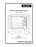
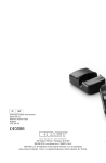
General Description
Figure 2.1: Monitor Front
B e
h
x
i
SYS (mmHg)
120
10
f
DIA (mmHg)
80
MAP
%SpO2
98
90 60
p
(mmHg)
f n
a Z
d
o
Parameters
The V6004 is a Non-Invasive Blood Pressure (NIBP) monitor with optional oximetry. NIBP
parameters include systolic, diastolic, and mean arterial pressures and pulse rate. Alarm
limits can be set on all monitored parameters.
NIBP
The NIBP function of the monitor is designed for use with large and small animals. A variety
of disposable and reusable cuffs are available for monitoring small to large animals. The
NIBP function of the monitor must be in small animal mode (SA) to be used on small
animals.
Oximeter (optional)
The monitor also supports oximetry, which continuously measures and displays arterial
blood oxygen saturation (SpO2) and Pulse Rate (p). Oximetry includes the display of a
pulse strength bar. The monitor beeps with each pulse beat. The volume of the pulse beep
is adjustable. The pitch of the pulse beep varies with the SpO2 value. A variety of veterinary
specific sensors are available.
Audio
The monitor uses a multi-frequency speaker for beeps and alarm and alert sounds. Volumes
are adjustable.
Serial Output
An RS-232C interface allows serial output of text data to a compatible device. There is no
waveform data on the serial output.
Power
The V6004 operates on power from an external power supply. In addition, the monitor
contains an internal battery that allows operation for approximately six hours.
Printer (optional)
An optional printer may be installed, which prints Data Log and Trend information.
V6004 Operation Manual
2-1
Chapter 2: Intended Use and General Information
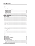
Front Panel
Figure 2.2: Monitor Front Panel
9
1
SYS (mmHg)
B e
120
h
x
g c
10
f
i
2
Display Name
1
Display
2
Charge LED (green)
3
4
3
DIA (mmHg)
80
5
f n
98
M
SENSOR
MAP
4
%SpO2
90 60
p
d
(mmHg)
6
a Z
c
7
o
8
Description
The display provides continual, real-time updates of all measured values, and
alarm or alert messages and/or indications. The display also shows a pulse
strength bar (if the oximeter is installed).
Is on steady while external power is applied and battery is fully charged. Indicates
battery is charging by blinking very slowly while external power is applied. If
there is no external power, then this LED is off.
Silence LED (yellow)
This Silence LED flashes during two-minute alarm silence. Stays on steady during
indefinite alarm silence.
ALERT LED (yellow)
The Alert LED is illuminated during a system alert.
g
c
“SENSOR” is illuminated when the sensor is not connected to the monitor, the
sensor is not attached to the patient, or to indicate a “searching too long” warning.
5
6
7
8
SENSOR LED (yellow)
Low Battery Indicator
M
ALARM LED (red)
c
SA Mode
(Small Animal Mode)
LA Mode
(Large Animal Mode)
9
Keys
2-2
WARNING! While “SENSOR” is illuminated, the monitor cannot
measure the patient’s SpO2 or pulse rate. You must
immediately check the patient’s condition. After you
have checked the patient’s condition, you must correct
the “SENSOR” low priority alarm/alert.
The low battery indicator is illuminated and a short burst of beeps occurs when
about 30 minutes of battery use remains. The monitor will work until the battery
becomes very weak, after which the monitor will turn itself off.
WARNING! When M is illuminated, you must immediately charge
the monitor’s battery. Otherwise, the monitor turns
itself off after about 30 minutes.
The Alarm LED flashes during patient alarms.
When light is illuminated, the NIBP function is in the Smaller Animal Mode. This is
the suggested mode for animals under 10 pounds.
When light is not illuminated, the NIBP function is in the Larger Animal Mode.
This is the suggested mode for animals greater than 10 pounds.
NOTE! Start with the LA Mode for all animals, and if you have
difficulty obtaining a reading, switch to the SA Mode.
The front panel keys control the monitor’s functions. Dedicated keys are provided
for turning the monitor on and off, silencing alarm and alert tones, selecting
menus, and additional NIBP functions.
V6004 Operation Manual
Chapter 2: Intended Use and General Information
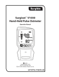
Display
Figure 2.3: Monitor Front Panel Parameter Items
2
1
SYS (mmHg)
120
gc
10
f
6
7
DIA (mmHg)
80
%SpO2
98
c
M
SENSOR
MAP
4
90 60
p
(mmHg)
3
5
Parameter
Description
1
SYS (mmHg)
This area displays the systolic pressure in mmHg. (millimeters of Mercury)
2
DIA (mmHg)
This area displays the diastolic pressure in mmHg.
3
MAP (mmHg)
This area displays the mean arterial pressure in mmHg.
4
%SpO2
This area displays the SpO2 measurement.
This area displays the pulse rate measurement in bpm.
p
5
NOTE! Dashes displayed in any parameter indicate the
measurement is invalid or unavailable.
Periodically indicates the time since the last NIBP reading, up to 99 minutes. For
more than 99 minutes, the interval display section will show “99 ” (with a trailing
decimal point).
.
f (INTERVAL)
6
In Auto NIBP mode, alternates between the NIBP interval and the time since the
last NIBP reading.
7
Pulse Strength Bargraph
Indicates the patient’s pulse activity and strength. The bargraph is logarithmically
scaled to indicate a wide range of pulse strengths.
Side Panel
Figure 2.4: Monitor Side Panel
1
NIBP
% SpO2 q
2
Connector
Description
1
NIBP Connector
The NIBP hose is connected here.
2
SpO2 Connector
The oximeter sensor and/or the extension cable is connected here.
V6004 Operation Manual
2-3
Chapter 2: Intended Use and General Information
Keys
B e
2
Figure 2.5: Keys
4
3
SYS (mmHg)
DIA (mmHg)
8
%SpO2
7
h
x
i
1
5
f
MAP
(mmHg)
p
f n
a Z
d
9
10
o
6
WARNING! Verify that all LEDs (light emitting diodes) on the display light up upon startup of the device.
Key name
1
2
3
x
h
B
Description
ON/OFF Press this key turns the monitor ON and OFF.
START Press this key to start a manual NIBP measurement, or, when in a user
menu, to save current settings and exit.
ALARM SILENCE Press this key to disable the audible alarm tone for two
minutes. (Yellow silence g LED flashes.) Pressing and holding this key for
about three seconds disables the alarm tone indefinitely. (Yellow silence g
LED is lit and not flashing.) Pressing this key momentarily cancels either alarm
silence condition.
The monitor defaults to two minute alarm silence at power up.
4
5
6
e
CANCEL Press this key to stop an NIBP measurement that is in progress. The
cuff will automatically deflate when this key is pressed. Pressing e for (3) three
seconds restores the initial cuff inflation pressure to 200 mmHg* in SA mode
or 175 mmHg in LA mode, and causes the NIBP display areas to show dashes.
This key is also used to exit user menus without saving new settings, and to
acknowledge NIBP alarms and alerts.
* Note: In Japan, the initial cuff inflation pressure is reset to 150 mmHg when in SA
mode.
i
STAT Press this key to begin Stat mode, in which NIBP readings are taken
continuously for 5 minutes. Upon exiting Stat mode (either after 5 minutes of Stat
mode readings, or when the user presses e to exit Stat mode), the monitor will
resume normal operation in Auto mode with a 5 minute interval.
d
MANUAL/AUTO Press this key to toggle between Manual and Auto NIBP mode.
In Auto mode, NIBP measurements are made at regular, user-selectable intervals.
In Manual mode, the user must initiate each NIBP measurement by pressing the
h key
7
a
8
f
2-4
RECALL Press this key once to enter Recall mode. Saved NIBP and SpO2 data will
be displayed along with the time at which each measurement was taken.
Press a for 6 seconds to show “[{r” steady on the display and clear the trend
memory. If the key is released while “[{r” is flashing, trend is not cleared.
INTERVAL Press this key once to set the NIBP measurement interval. Press and
hold for 3 seconds to set the time and date.
V6004 Operation Manual
Chapter 2: Intended Use and General Information
key name
description
ARROWS During normal operation, the ARROW keys (no )are used to set
Alarm/Alert volume when alarms are not silenced, and pulse beep volume when
alarms are silenced. The ARROW keys are used to set the NIBP measurement
interval, the time and date, alarm limits, and system settings, in various user
modes.
no
9
During normal operation, pressing and holding the n (UP) key for 3 seconds
initiates a data log to the printer or serial port.
When in Recall mode, pressing the n and o keys scrolls through saved data,
and pressing and holding the n key for 3 seconds causes all saved data (trends)
to be sent to the printer or serial port.
ALARM SET Press this key to enter the System Settings menu and Alarm Limits
menu. While menus are displayed, press Z to select a menu item or to accept
a value which has been adjusted.
Press this key once to enter the Alarm Limits menu. Use the no keys to adjust
the limit values and the Z to cycle through the alarm limits.
Press and hold the Z key for 3 seconds to enter the System Settings menu.
The following system settings may be changed: initial cuff inflation pressure, data
log/trend output destination, and display intensity.
Z
10
Rear Panel
Figure 2.6: Monitor Rear Panel
1
2
F
PRINTER OUTPUT
2 6 - 8V ----- - - 0.35A
Connector name
1
2
Serial I/O
Power Input
V6004 Operation Manual
ONLY USE
ADAPTER
2 AC
INPUT 24V ----- - - 1.5A
description
An external RS-232C communication device can be connected to the monitor
through this port.
The external power supply attaches to this connector.
2-5
Chapter 2: Intended Use and General Information
This page is intentionally left blank.
2-6
V6004 Operation Manual
Chapter 3: Setting Up the Monitor
Chapter 3: Setting Up the Monitor
Unpacking the Monitor and Checking the Shipment
Carefully remove the monitor and accessories from the shipping carton. Save the packing materials in case the
monitor or accessories must be shipped or stored. Compare the packing list with the accessories received and
make sure the shipment is complete.
CAUTION! If damage has occurred to the package, a calibration needs to be done at an authorized
service center.
Turning Alarm and Alert Tones On and Off
When the monitor is turned on, the alarm and alert tones are silenced for two minutes. The SILENCE g LED
flashes during the two minute time-out.
• To silence the alarm and alert tones indefinitely: Press and hold B for about three seconds; the g
LED lights steady.
• To silence the alarm and alert tones for two minutes: Momentarily press B; the g LED flashes. If
tones are already silenced, press B twice (the first press cancels alarm silenced; the second press silences
the alarms for two minutes).
• To cancel either two minute or indefinite alarm silence and enable alarm and alert tones: Momentarily
press B; the g LED turns off.
Working With System-Wide Settings
This section describes working with system-wide settings using the System Settings mode.
1. To enter the System Settings mode press and hold the ALARM SET
Z key for 3 seconds.
2. The patient mode, “La” will display in the systolic and diastolic display areas. This is the mode of choice for
animals 10 pounds or larger. “sa” is used for animals under 10 pounds.
3. Press the Z key again to edit the initial cuff inflation pressure that is displayed in the systolic display area.
Use the n and o keys to set this value.
4. Pressing the Z key again displays the data logging/trends output destination in the MAP display area.
Use the n and o keys to toggle between “Prnt” for optional integral printer output and “Port” for
serial port data output.
NOTE! If the printer has not been factory installed, this setting will always show “Port.”
5. Press the Z key again to view the display intensity in the INTERVAL f area. Use the n and o keys to
change the intensity.
6. Press START h or Z to save the new settings and exit. Pressing CANCEL e exits without saving the
new settings.
V6004 Operation Manual
3-1
Chapter 3: Setting Up the Monitor
Setting the Time or Date
The monitor has a real-time clock and calendar. It remembers the time and date, even when the monitor is
turned off or is not connected to the external charger. The time and date are used for the trends and printouts.
To set the time and/or date, do the following:
1. Press and hold the INTERVAL f key for 3 seconds.
2. The system time will be displayed in the MAP display area (HH.MM), and the date will be displayed in the SYS
and DIA display areas (MM.DD.YY).
3. Use the f key to select the time or date item to be changed.
4. Use the n and o keys to adjust the value. Pressing and holding the n and o key changes the value
faster.
5. Press the f key to accept the value and move on to the next.
6. When the year is flashing, press the f key to accept the changes and exit. Pressing the h key also saves
the new settings and returns the monitor to normal operation. Pressing the e key exits without saving the
new settings.
Optional Printer
1. Press the FEED (
) key to advance/install paper.
2. Press the PRINT (F) key to begin printing.
AC Power
CAUTION! Ensure the device’s AC rating is correct for the AC voltage at your installation site before using
this monitor. The monitor’s AC rating is shown on the external power supply. If the rating is
not correct, do not use the monitor; contact the Smiths Medical PM, Inc. Service Department,
or your local distributor, for help.
Refer also to Chapter 11: Optional Supplies and Accessories to verify the proper AC power supply for your
application.
NOTE! Connect the AC Charger to the AC Power Connector of the monitor first and the AC Charger to the
Wall Outlet second.
NOTE! Do not plug the monitor into an outlet controlled by a wall switch.
1614
AC power supply 105-125V, 60 Hz
1615
AC power supply 208-252V, 50/60 Hz
1616
AC power supply 90-110V, 50 Hz
NOTE! When using AC power, the Oximeter is a class II device with functional earth. This earth
connection is for device electromagnetic compatibility and does not provide protection to the
patient or user.
WARNING! Disconnect the AC power supply from the outlet before disconnecting it from the monitor.
Leaving the AC power supply connected to an AC power outlet without being connected to
the monitor may result in a safety hazard.
3-2
V6004 Operation Manual
Chapter 3: Setting Up the Monitor
WARNING! Do not allow any moisture to touch the AC power supply connectors or a safety hazard may
result. Ensure that hands are thoroughly dry before handling the AC power supply.
WARNING! Do not place the monitor in the patient’s bed. Do not place the monitor on the floor.
WARNING! Failure to place the monitor away from the patient may allow the patient to turn off, reset, or
damage the monitor, possibly resulting in the patient not being monitored. Make sure the
patient cannot reach the monitor.
WARNING! Failure to carefully route the cable from the sensor to the monitor may allow the patient to
become entangled in the cable, possibly resulting in patient strangulation. Route the cable
in a way that will prevent the patient from becoming entangled in the cable. If necessary, use
tape to secure the cable.
WARNING! If there is a risk of the AC power supply becoming disconnected from the monitor during use,
secure the cord to the monitor several inches from the connection.
V6004 Operation Manual
3-3
Chapter 3: Setting Up the Monitor
This page is intentionally left blank.
3-4
V6004 Operation Manual
Chapter 4: Alarms and Alerts
Chapter 4: Alarms and Alerts
Alarms
An alarm warns you when a patient’s measurement matches or exceeds the high or low alarm limit for that
measurement. For example, if the high SYS alarm limit is set to 150, and the patient’s measured SYS is 150 or
higher, an alarm is triggered. During an alarm:
Figure 4.1: Alarm Example
B e
h
x
SYS (mmHg)
150
10
f
i
DIA (mmHg)
80
110
MAP
(mmHg)
2
1
The c LED flashes.
2
The digits for the violated alarm limit flash.
%SpO2
f n
98
c
a Z
60
p
d
o
1
The alarm tone sounds (if not silenced).
NOTE! The alarm actions occur for each violated alarm, even if more than one alarm is violated at the
same time.
NOTE! Alarms can be tested while the monitor is in use by setting alarm limits such that the measured
parameter reading is outside the alarm limits. Be sure to restore alarm limits to the required
settings after testing.
Manually Reset NIBP Alarms
The NIBP alarms require a manual reset. The alarm actions stop when the alarm is no longer violated and the
CANCELe key is pressed.
V6004 Operation Manual
4-1
Chapter 4: Alarms and Alerts
Alerts
An alert warns you about a condition that prevents the monitor from taking a measurement. For example, if the
SpO2 sensor is not connected to the monitor, the monitor cannot measure the patient’s pulse rate or SpO2 value.
In this case, an alert is triggered. During an alert:
Figure 4.2: Alert Example
B e
h
x
SYS (mmHg)
DIA (mmHg)
2
%SpO2
210 130 --c
i
10
f
110 60
p
MAP
(mmHg)
1
1
The c LED is illuminated.
2
Dashes indicate a measurement is unavailable.
f n
a Z
d
o
3
The alert tone sounds (if not silenced).
3
A message, “E-nn”, (“nn” is an error number), is displayed in the MAP area (for NIBP only).
Adjusting or Viewing Alarm Limits
1. Press the Z key once to enter the Set Alarms mode.
2. Using the Z key, select the alarm limit to be changed.
3. Use the arrow keys to adjust the value. Press the Z key to set the value. High alarm limits may be set to
OFF by scrolling past the highest setting. Low alarm limits may be set to OFF by scrolling past the lowest
setting
NOTE! The SpO2 function, the monitor may be disabled by scrolling its high alarm limit to 100, then OFF,
and then to “-d-.”
4. Press Z to access other alarm limits.
5. Press the Z key to toggle through the menu or press the h key to save the new settings and exit.
Pressing e exits without saving the changes.
NOTE! Alarm limits are retained during power cycles, except for the following note.
NOTE! If the low alarm limit for SpO2 is set to a value lower than 80 when the monitor is powered down,
then this low alarm limit will be reset to 85 at power up.
4-2
V6004 Operation Manual
Chapter 4: Alarms and Alerts
Alarm and Alert Tones
The alarm tone is a two tone, continuous sound (dee doo dee doo). The tone for all alerts except low battery is a
single tone sound with a pause (beep beep, pause, beep beep).
• The alarm and alert tones sound at the same volume.
• The volume can be adjusted by doing the following:
a. Make sure the alarms are not silenced.
b. Press the n or o keys to either increase or decrease the volume. The volume level will be displayed
in the lower left corner of the display.
• This volume can not be set to OFF.
• All alarm and alert tones except the Low Battery alert can be silenced with the B key.
Turning Alarm and Alert Tones On and Off
When the monitor is turned on, the alarm and alert tones are silenced for two minutes. The g LED on the B
key flashes during the two minute time-out.
• To silence the alarm and alert tones indefinitely: Press and hold B for about three seconds. The g
LED lights steady, and you will hear a beep.
• To silence the alarm and alert tones for two minutes: Momentarily press B; the g LED flashes. If
tones are already silenced, press B twice (the first press cancels alarm silenced; the second press silences
the alarms for two minutes).
• To cancel either two minute or indefinite alarm silence and enable alarm and alert tones: Momentarily
press B; the g LED turns off.
System Alert Condition: Low Battery
A low battery condition will be detected when the battery has about 30 minutes remaining. When the condition
is detected:
• The M LED is illuminated.
• This message remains displayed until the monitor is connected to power.
• A unique alert tone, a burst of 5 beeps at mid-volume, sounds as soon as the low battery condition is
detected, and every 30 seconds thereafter while the condition persists.
• The volume of the low battery alert tone is not adjustable.
• The low battery audible cannot be disabled by the B key.
V6004 Operation Manual
4-3
Chapter 4: Alarms and Alerts
Audible and Visual Indicators
Each audible indicator is assigned a priority level, so only one tone sounds at a time. The monitor also provides
visual indication of alarm conditions via on-screen displays and front panel indicators. The indicator tones and
visual responses are described below.
INDICATION
TYPE
DISPLAY
INDICATOR
ALARMS
(High Priority)
Numbers flash that
correspond to the
parameter alarm (SYS,
DIA, MAP, SpO2, and/
or Rate)
Red ALARM
(c)LED flashes
Overrides ALERT
(audio tones)
Alarm tone sounds ten
pulses, repeated every
ten seconds.
N/A (not applicable)
N/A
N/A
N/A
ALERTS
(Low priority)
N/A
Yellow ALERT
(c)LED is
illuminated
Overrides pulse beeps
Low priority alarm/
Alert tone sounds two
pulses, repeated every
20 seconds
ALERTS
(Low priority)
N/A
Yellow SENSOR LED is
illuminated
Overrides pulse beeps
Low priority alarm/
Alert tone sounds two
pulses, repeated every
20 seconds
ALERTS
(Low priority)
N/A
Yellow
BATT (M) LED is
illuminated
Overrides all audio
(one shot)
6 beeps that occur
once every 30 seconds
10 segment bar graph
N/A
N/A
Beeps with each
heart/pulse beat.
The beep pitch
corresponds to the
SpO2 value. As the
SpO2 value increases,
the beep pitch
increases. Conversely,
as the SpO2 value
decreases, the beep
pitch decreases.
N/A
N/A
N/A
Clicks when a key is
pressed.
ALARMS
(Medium priority)
Pulse
Key click
4-4
LED
INDICATOR
EFFECT
AUDIO
V6004 Operation Manual
Chapter 5: Non-Invasive Blood Pressure
Chapter 5: NIBP
Theory of Operation
The monitor uses oscillometric principles to calculate the systolic, diastolic, and mean arterial pressure (MAP)
values. The MAP is calculated as the lowest cuff pressure that provides the maximum cuff oscillations. Therefore,
the MAP is the largest signal received and is the most accurate reading using oscillometric methods. Systolic
pressure is calculated as the cuff pressure when an increase in perceived cuff oscillations begins. The diastolic
pressure is the cuff pressure when oscillations are no longer decreasing as pressure is released from the cuff.
The first and fourth Korotkoff sounds were used to determine the overall efficacy.
Using the NIBP Parameter
If you are not familiar with this monitor and the NIBP parameter, then follow this chapter’s sections in order:
• Connecting the Cuff and Hose: Connect the cuff to the patient and the hose to the cuff and monitor.
• Verifying the Initial Cuff Inflation Pressure: Verify the initial cuff inflation pressure setting.
• Taking NIBP Measurements: Describes how to take Manual, Automatic, and Stat measurements, and how
to cancel measurements.
• NIBP Alerts and Messages: Defines the NIBP alerts and messages.
• Application Note: NIBP Cuff Inflation Method: Describes the method used to determine the cuff inflation
pressure for each measurement.
Connecting the Cuff and Hose
Choose the appropriate size cuff. Below are the ranges to use when deciding which seize cuff to use.
Patient
Description
Small Mammals, Cats, & Small Dogs (or similar size
animals)
31543B1: Extra Small Cuff
Small-Medium Dogs (or similar size animals)
315432B2: Small Cuff
Medium-Large Dogs (or similar size animals)
31543B3: Medium Cuff
Large Dogs (or other large animals)
31543B4: Large Cuff
V6004 Operation Manual
5-1
Chapter 5: Non-Invasive Blood Pressure
Suggested Application Sites
Figure 5.1: Suggested Application Sites
Cuffs can be placed on a variety of locations, including:
• Median palmar artery (proximal to the metacarpal pad)
• Over the dorsal pedal artery (on the dorsomedial aspect of the hind limb below the hock)
• Over the coccygeal artery on the ventral aspect of the base of the tail
• Over the femoral artery on the medial aspect of the thigh (use this location last, the other locations
usually give better readings)
Connect the Cuff and Hose
1. Attach the hose to the monitor.
2. Select the appropriate cuff for your patient. See table on page 5-1 for guidance.
3. Place the cuff on the limb with the SurgiVet® logo facing up, away from the patient. The width of the cuff
should be approximately 30-60% of the circumference of the limb. Remember that you do not need to align
along an artery.
4. Secure the Hook & Loop closure. The cuff should be snug.
5. Attach the cuff to the hose and initiate the inflation of the cuff.
6. Lift the Hook & Loop closure tap to remove the cuff.
Note! The Hook & Loop closure system is designed so that it will not come apart, unless the cuff is
placed incorrectly or is too small for the patient.
5-2
V6004 Operation Manual
Chapter 5: Non-Invasive Blood Pressure
Verifying the Initial Cuff Inflation Pressure
NOTE! The NIBP parameter uses a special method for determining the cuff inflation pressure. For details
on this method, see Application Note: NIBP Cuff Inflation Method later in this chapter.
1. Verify that the cuff is on the correct setting. To access the initial cuff inflation pressure setting, press and
hold the Z key for 3 seconds. Either SA (for all cats and dogs under 10 lbs.) or LA (for all dogs and
animals, other than cats, 10 lbs. or larger) will display in the systolic area of the screen. Use the arrow key to
adjust between SA and LA Mode.
2. Press the Z key again to see the current initial cuff inflation pressure for the patient. Use the arrow key to
adjust the initial cuff inflation pressure.
Taking NIBP Measurements
Decide which measurement mode you want to use:
• Manual: In the Manual mode, a single NIBP measurement is taken when h is pressed.
• Automatic: In the Automatic mode, NIBP measurements are taken at regular intervals, according to the
interval setting when MANUAL/AUTO d is pressed and INTERVAL f selected.
• Stat: In the Stat mode, five minutes of successive NIBP measurements are taken when i is pressed.
Manual NIBP Measurement
In Manual mode, a single NIBP measurement is taken when h is pressed.
1. If the unit is in Auto mode, press the d key to place the unit in Manual mode. The f INTERVAL display
section will periodically display the time since the last NIBP reading, up to 99 minutes. For more than 99
minutes, the f INTERVAL display section will show “99.” (i.e., with the trailing decimal point).
2. Press h to begin the measurement. A digital manometer will display the current cuff pressure in the
SYS display section during the measurement. If the measurement is successful, the systolic, diastolic, and
MAP measured values are updated. Pulse Rate is also updated if the oximeter is disabled, not installed, or
oximetry Pulse Rate is invalid.
3. If the measurement is unsuccessful, dashes are shown for the measured values and the monitor stops taking
measurements until h is pressed again. An error message will be displayed in the MAP area. A message,
“E-nn”, (“nn” is an error number), is displayed in the MAP area (for NIBP only).
V6004 Operation Manual
5-3
Chapter 5: Non-Invasive Blood Pressure
Automatic NIBP Measurement
In the Auto mode, NIBP measurements are taken at the auto measurement interval setting.
1. If the unit is in Manual mode, press the d key to enter Auto mode. The measurement interval will be
displayed in the f INTERVAL area, alternating with the time since last NIBP reading.
2. Press the h key to begin a single NIBP measurement immediately; the automatic mode continues after
the single measurement. If the measurement is successful, the measured systolic, diastolic, MAP, and pulse
rate values are updated. When the automatic measurement interval time has elapsed, another automatic
measurement is taken.
3. If the measurement is unsuccessful, dashes are shown for the measured values and the monitor stops taking
measurements until the measurement interval has elapsed. A message, “E-nn”, (“nn” is an error number),
is displayed in the MAP area. (for NIBP only)
Manual measurements may be initiated using the h key in Auto mode, provided that the cuff has been
deflated for at least 30 seconds; otherwise, the interval display will flash for a few seconds to indicate that the
monitor is in Auto mode and the cuff has been recently inflated. A Manual measurement will take the place of
an Auto measurement if the measurement was scheduled to occur during the manual measurement. The NIBP
interval counter will be reset at the conclusion of a successful manual measurement.
NOTE! After (10) ten minutes of Auto mode measurements at 1 minute intervals, the monitor will switch
to an interval of 5 minutes.
Stat NIBP Measurement
In Stat mode, five minutes of successive NIBP measurements are taken.
1. Press the i key.
2. The digital manometer will not be displayed, and “--” will be displayed in the f INTERVAL display section
to indicate Stat mode.
3. When the i key is pressed, a five-minute time-out is started. NIBP measurements are taken successively
until the five-minute time-out has elapsed, or until the i key is pressed. If an NIBP alarm or alert is
occurring, the first press of the e key will acknowledge the alarm(s) and /or alert(s); the second press of the
e key will end Stat mode.
NOTE! When the Stat mode times out or is canceled, Stat NIBP measurements stop and the monitor is set
to the Auto measurement mode with an interval setting of 5 minutes.
Canceling NIBP Measurements
Pressing e performs these functions:
• Stops the current measurement. While in the automatic mode, pressing e only stops the current
measurement; another automatic measurement starts after the preset time interval has elapsed.
• Stops all NIBP alarm and alert actions, and erases displayed NIBP alerts and messages.
• Pressing e for 3 seconds restores the initial cuff inflation pressure to 200 mmHg, in SA mode or 175
mmHg in LA mode. (In Japan, the initial cuff inflation pressure is reset to 150 mmHg if in SA mode).
Pressing this key for three (3) seconds causes the NIBP display areas to show dashes.
5-4
V6004 Operation Manual
Chapter 5: Non-Invasive Blood Pressure
Changing the Auto NIBP Measurement Interval
The automatic NIBP measurement interval setting is shown in the f INTERVAL display area when Auto mode is
chosen. This setting is the time interval between automatic NIBP measurements. Follow these steps to change
the Auto NIBP measurement interval:
1. Press the f key.
2. The Auto mode NIBP interval will display in the f INTERVAL display area.
3. Use the n and o keys to change the Auto measurement interval setting.
4. Press either the f key or the h key to save the setting and exit. Pressing the e key exits the mode
without saving the new interval setting.
NOTE! If no key is pressed for 20 seconds while in SET INTERVAL mode, the unit will return to normal
operation with the new interval setting.
NOTE! If the unit is in Auto mode when the interval setting is changed, the unit will continue to run in
Auto mode with the new interval when the Set Interval mode is exited.
NOTE! If the INTERVAL was changed, the NIBP Auto mode interval will be restarted when the Set Interval
mode is exited.
NOTE! If the unit is in Auto mode, and it is time to take a measurement, the unit will automatically exit
the Set Interval mode, with the new interval setting, and start a measurement.
V6004 Operation Manual
5-5
Chapter 5: Non-Invasive Blood Pressure
NIBP Alerts and Status Messages
The NIBP status messages are displayed in the MAP display area. Only one message can be shown at a time;
therefore, they are prioritized to show what is most important on the display.
Status Messages
Press the e key to acknowledge the alert. The message disappears, the ALERT LED ( c )turns off, and the
alert tone silences. If the status message (i.e., “E-nn”) does not disappear, the condition has not been removed
and will require additional attention as described below.
error code
meaning
action
E-11
Processor communication error.
Turn the unit off and then on. Try the reading again. If the
message reappears contact Smiths Medical PM, Inc. Veterinary
Clinical Support.
E-12
Measurement timed out.
Try the reading again. Check patient condition and cuff
placement. Initial inflation pressure may need to be increased.
E-13
Cuff leak.
Check the cuff and hose assembly for leaks and try the reading
again. If the message reappears, replace the cuff.
E-15
Excessive noise or inflation pressure
too low.
Try the reading again. Check patient condition and cuff
placement. Initial inflation pressure may need to be increased.
E-16
Weak signal.
Try the reading again. Reposition the cuff over the artery if
necessary.
E-17
System error.
Turn the unit off and then on. Try the reading again. If the
message reappears contact Smiths Medical PM, Inc. Veterinary
Clinical Support.
E-18
Cuff overpressure condition.
Check patient condition. This message will appear if the
pressure exceeds 315 mmHg.
E-19
Time error.
Turn the unit off and then on. Try the reading again. If the
message reappears contact Smiths Medical PM, Inc. Veterinary
Clinical Support
E-20
NIBP calibration out of range.
Contact Smiths Medical PM, Inc. Veterinary Clinical Support.
E-21
NIBP dump valve failure.
Contact Smiths Medical PM, Inc. Veterinary Clinical Support.
E-22
PIC pressure transducer error.
PIC pressure transducer is outside the specified range at
initialization. Try the reading again. If the message reappears,
contact Smiths Medical PM, Inc. Veterinary Clinical Support.
E-23
Pressure transducer error.
Pressure transducer is outside the specified range at
initialization. Try the reading again. If the message reappears,
contact Smiths Medical PM, Inc. Veterinary Clinical Support.
Application Note: NIBP Cuff Inflation Method
The NIBP cuff inflation pressure is determined by the following method.
If:
• you just turned on the monitor
• there is no valid systolic pressure reading
• you just changed the initial cuff inflation pressure setting
Then the cuff pumps up to the initial cuff inflation pressure setting in the SYSTEM SETTINGS menu.
If there is a valid systolic pressure reading, then the cuff pumps up to the previous systolic reading plus 35 mmHg.
5-6
V6004 Operation Manual
Chapter 6: Using the Oximeter Option
Chapter 6: Using the Oximeter Option
General Description
The V6004’s Oximeter option noninvasively and continuously monitors and displays arterial blood oxygen
saturation (SpO2) and pulse rate. The V6004 beeps with each pulse beat. The pitch of the pulse beep depends on
the SpO2 value; the higher (or lower) the SpO2 value, the higher (or lower) the pulse beep pitch.
The V6004’s flexible alarm system lets you choose alarm parameters and audible tone volumes. You can select
the high and low alarm limits for SpO2 and pulse rate, and independently choose the volume for alarm and pulse
beep tones.
Pulse Oximetry Theory of Operation
The pulse oximeter determines %SpO2 and pulse rate by passing two wavelengths of low intensity light, one red
and one infrared, through body tissue to a photodetector. Information about wavelength range can be especially
useful to clinicians. Wavelength information for this device can be found in the SpO2 Specifications section of
this manual.
Pulse identification is accomplished by using plethysmographic techniques, and oxygen saturation
measurements are determined using spectrophotometric oximetry principles. During measurement, the signal
strength resulting from each light source depends on the color and thickness of the body tissue, the sensor
placement, the intensity of the light sources, and the absorption of the arterial and venous blood (including the
time varying effects of the pulse) in the body tissues.
Figure 6.1: Pulse Oximetry Theory of Operation
1
2
1
Low intensity Red and Infrared LED light sources
2
Detector
Oximetry processes these signals, separating the time invariant parameters (tissue thickness, skin color, light
intensity, and venous blood) from the time variant parameters (arterial volume and SpO2) to identify the pulses
and calculate functional oxygen saturation. Oxygen saturation calculations can be performed because blood
saturated with oxygen predictably absorbs less red light than oxygen-depleted blood.
WARNING! Since measurement of SpO2 depends on a pulsating vascular bed, any condition that
restricts blood flow, such as the use of a blood pressure cuff or extremes in systemic vascular
resistance, may cause an inability to determine accurate SpO2 and pulse rate readings.
V6004 Operation Manual
6-1
Chapter 6: Using the Oximeter Option
WARNING! Under certain clinical conditions, pulse oximeters may display dashes if unable to display
SpO2 and/or pulse rate values. Under these conditions, pulse oximeters may also display
erroneous values. These conditions include, but are not limited to: patient motion, low
perfusion, cardiac arrhythmias, high or low pulse rates or a combination of the above
conditions. Failure of the clinician to recognize the effects of these conditions on pulse
oximeter readings may result in patient injury.
NOTE! Pulse rate will be provided by the NIBP function. When the SpO2 option is enabled and is
providing valid data, its pulse rate will override the NIBP pulse rate.
Disabling the Oximetry Option
1. Press the Z key once to enter the Set Alarms mode.
2. Using the Z key, select the high oximetry alarm limit.
3. Use the arrow keys to adjust the value. The monitor may be disabled by scrolling the high alarm limit to 100,
then OFF, and then to “-d-.” Press the Z key to set the value.
4. Press the Z key to toggle through the menu or press the h key to save the new settings and exit.
Pressing e exits without saving the changes. The oximetry functions are disabled, as denoted by the “d-” in the %SpO2 area, and may be re-enabled by repeating steps 1-3 and selecting either OFF or a specific
high alarm limit value.
Adjusting the Pulse Beep Volume
1. Make sure that alarms are silenced.
2. Use the n and o keys to adjust the pulse volume. The pulse volume level will be displayed in the lower
left corner of the display (in the f INTERVAL area).
NOTE! The pulse beep sounds while adjusting the volume.
Attaching the Patient – Oximetry
Smiths Medical PM, Inc. manufactures a variety of SurgiVet® pulse oximetry sensors to allow you to accurately
and reliably monitor all of your different types and weights of patients. It is very important to select the proper
sensor for each patient based on their size, color, condition, and type of procedure you are performing.
Experience will quickly teach you which probes work best under different conditions. Well-perfused sites,
with little or no hair are preferable. It is also important to note that some anesthetic drugs such as xylazine,
acepromazine, and domitor, can affect peripheral pulse pressures causing very weak pulsations. All pulse
oximeters require a good pulse to work properly. The sensors available to you for your SurgiVet® pulse oximeters
include a mini clip sensor, a Lingual Sensor, a reflectance sensor, and a Universal ‘C’ sensor.
6-2
V6004 Operation Manual
Chapter 6: Using the Oximeter Option
Choosing the Sensor
Choose the appropriate sensor from the following chart.
patient
site
Small/Medium Animal Tongue
up to 60 pounds
Pinna (ears), Toe Webbing,
Tongue
Rectum/Tail
sensor #/Description
V1703: Lingual Clip Set with ‘Y’ Sensor
V3078: Mini Clip Sensor
V1700: Reflectance Sensor
Hock, Achilles Tendon, etc. V1707: Universal ‘C’ Sensor
Large Animals over
60 pounds
Tongue
Pinna (ears), Toe Webbing,
Tongue
Rectum/Tail
V1703: Medium/Large Animal Lingual Clip Set with ‘Y’
Sensor
V3078: Mini Clip Sensor
V1700: Reflectance Sensor
Hock, Achilles Tendon, etc. V1707: Universal ‘C’ Sensor
Equine
NOTE!
Tongue
V1707: Universal ‘C’ Sensor
2 Refer to sensor insert instructions for application directions.
Clean or Disinfect the Sensors
Clean or disinfect the sensor before attaching a new patient.
WARNING! Do not autoclave, ethylene oxide sterilize, or immerse the sensors in liquid.
CAUTION! Unplug the sensor from the monitor before cleaning or disinfecting.
Clean the sensor with a soft cloth moistened in water or a mild soap solution. To disinfect the sensor, wipe the
sensor with isopropyl alcohol.
Checking the Sensor and Oximetry Cable
Follow these instructions each time before you attach the sensor to the patient. This helps ensure the sensor and
oximetry cable are working properly.
WARNING! Using a damaged sensor may cause inaccurate readings. Inspect each sensor. If a sensor
appears damaged, do not use it. Use another sensor or contact your authorized repair center
for help.
WARNING! Using a damaged oximetry cable may cause inaccurate readings. Inspect the oximetry cable.
If the oximetry cable appears damaged, do not use it. Contact your authorized repair center
for help.
Carefully inspect the sensor to make sure it does not appear damaged.
If using the oximetry cable, carefully inspect the oximetry cable to make sure it does not appear damaged.
V6004 Operation Manual
6-3
Chapter 6: Using the Oximeter Option
Figure 4.3: Attaching Sensor And Oximetry Cable To Monitor.
B e
SYS (mmHg)
h
1
Oximetry Cable
2
Connector Retaining Clip
3
Sensor
x
1
2
DIA (mmHg)
%SpO2
c
i
MAP
c
(mmHg)
p
f n
a Z
d
o
3
If using the oximetry cable:
1. If the sensor is not already connected to the oximetry cable, connect the sensor to the oximetry cable as
shown. Push the connectors together firmly and close the latch to secure the connectors.
2. If the oximetry cable is not already connected to the monitor, connect the oximetry cable to the monitor as
shown. Push the connector firmly into the monitor.
3. You are now ready to attach the sensor to the patient.
WARNING! Failure to carefully route the cable from the sensor to the monitor may allow the patient to
become entangled in the cable, possibly resulting in patient strangulation. Route the cable
in a way that will prevent the patient from becoming entangled in the cable. If necessary, use
tape to secure the cable.
If not using the oximetry cable:
1. Connect the sensor to the monitor. Push the connector firmly into the monitor.
WARNING! If any of the integrity checks fail, do not attempt to monitor the patient. Use another sensor
or oximetry cable, or contact the equipment dealer for help if necessary.
Attach the Sensor to the Patient
WARNING! Prolonged use or the patient’s condition may require changing the sensor site periodically.
Change sensor site and check skin integrity, circulatory status, and correct alignment at least
every 4 hours.
WARNING! When attaching sensors with Microfoam® tape, do not stretch the tape or attach the tape too
tightly. Tape applied too tightly may cause inaccurate readings and blisters on the animal’s
skin (lack of skin respiration, not heat, causes the blisters).
6-4
V6004 Operation Manual
Chapter 6: Using the Oximeter Option
Application Guide
Universal ‘Y’ (Lingual) Sensor
Figure 6.2: Universal ‘Y’ Sensor
Your monitor is equipped with a lingual sensor. Position the lingual clip on the base of the tongue, and
placement is dependent on the thickness of the tongue. Start at the tip and work your way towards the base.
Always direct the light downward (towards the floor) regardless of the animal’s position to reduce the effects of
ambient light. Keep the tongue moist during longer procedures and monitor for significant temperature loss.
Ensure that there is a minimum of 2 pulse strength bars displayed on the pulse oximeter.
If necessary, the lingual clip may also be positioned on lips, cheeks, prepuce, vulva and hocks. Moisten the hock
area with isopropyl alcohol, water, and clip hair if needed. To get better reading on the smaller tongues, fold the
sides of the tongue up into a taco shape and pass the light through both layers. Don’t fold the tip of the tongue
back because you will restrict blood flow to the tongue.
Mini Clip
Figure 6.3: Mini Clip
The Mini Clip is much like the Universal ‘Y’ lingual sensor, but less than a quarter of the size of the lingual clip.
The smaller clip proves effective on the small breeds and especially on smaller cats. The clip will work on a cat’s
ear, tongue, and toe webbing. The Mini Clip also works well on larger animals.
V6004 Operation Manual
6-5
Chapter 6: Using the Oximeter Option
Universal ‘C’ sensor
Figure 6.4: Universal ‘C’ Sensor
The ‘C’ sensor is designed specifically for use in the larger tissue areas. It has brighter LED’s and therefore will
shine through thicker tissues. The ‘C’ sensor can effectively be applied to the tongue or lip of larger dogs and
equine. It can also be applied across the Achilles tendon, across the metatarsals or metacarpals of cats and dogs,
on vulva, tails and across the front leg of smaller animals. The ‘C’ has a space between the two LED’s. The tissue
needs to be at least that thick to get an SpO2 reading.
Reflectance Sensor
Figure 6.5: Reflectance Sensor
The reflectance sensor is an excellent sensor to use if you are doing dental procedures or other oral work that
precludes you from using the lingual clip.
Clean the reflectance sensor by wiping it down with isopropyl alcohol or chlorhexidine. A thin coating of
lubricant can be used, ensuring that the two LED’s are kept clean and free of lubricant. This sensor may be used
in the esophagus or cloaca of reptiles and large avians.
The animal does not need to be anesthetized when using the reflectance sensor, making it very useful in critical
care or post operative settings and for spot checking. A simple glove swipe to remove existing feces may be
needed. The sensor is placed very shallow, just so the 2 LED’s are covered, reading the perfusion around the
sphincter. A slight rotation may be needed to insure that the LED’s are up against tissue and not in fecal material.
6-6
V6004 Operation Manual
Chapter 6: Using the Oximeter Option
Figure 6.6: Reflectance Sensor
2
1
3
1
Reflectance Sensor
2
Secure the sensor to the tail with a non-adhesive wrap
3
Lights should be positioned as shown
The reflectance sensor may also be placed on the ventral base of the tail. The LED’s should be positioned
dorsally. You may need to clip a small patch of hair, only large enough for the LED’s to lay on the skin, and clean
surface. Hold the sensor snugly against the tail and wrap with non-adhesive wrap.
Pulse Oximeter Sensor Application Tips
There is some variation depending on the manufacturer, but there are three basic types of pulse oximeter
sensors made for the small animal patient:
• Lingual sensor
• ‘C’ sensor
• Reflectance (rectal, esophageal)
It is very important to have a variety of sensors in order to monitor the majority of the small animal patients. It is
also important to select the proper sensor for animals based on their size, color, fur type, medical condition, and
type of procedure.
Testing Sensor Function
1. To test the lingual clip function, turn on the monitor with the lingual sensor attached. View the sensor
to make sure a red light is being emitted, then place the sensor on a small finger (without nail polish). Rest
the hand with the sensor on it on a table to minimize motion. Note that in most cases the red light should
be shining in the same direction as the overhead or surgical lights. It is important that the light receptor
is shielded in order to avoid interference from ambient light. Once placed on a patient site, the red light
should be shining continuously. In some cases a blinking light indicates that the tissue thickness is either
too thin or thick. Once the sensor is placed properly, both the SpO2 and pulse rate should appear in a short
period of time (10-15 seconds).
2. Testing the ‘C’ sensor is performed in the same manner. This is a stronger sensor and can be used with
greater tissue thickness.
3. Testing the reflectance sensor is performed in the same manner, but it should be pressed between
thumb and index finger or into the palm of your hand.
V6004 Operation Manual
6-7
Chapter 6: Using the Oximeter Option
Primary Applications for Sensors
Lingual Sensor (Lingual and Mini Clip)
• The primary application site is the tongue for most animals. On cats and small dogs, fold the tongue like
a taco or use a wet gauze pad of single thickness folded over the tongue, and then place the sensor over
the gauze.
• Other sites include the prepuce or vulva of larger dogs, the achilles tendon of a cat or small dog, ears, or
toe webbing.
C Sensor
• For cats and small breed dogs, place the sensor on the thigh, metatarsal or metacarpal, or hock near the
saphenous vein.
• For larger breed dogs, place the sensor over the Achilles tendon, tongue, prepuce or vulva, or through toe
webbing.
• It may be necessary to wet and part the fur with water in order to get the sensor closer to the skin of the
patient.
Reflectance Sensor
• In most animals, wet and part the fur at the ventral tail base and non-adhesive tape (not tape) in place. It
may be necessary to shave a small spot on the ventral tail base in patients with a thick undercoat, such as
a Husky.
Limitations
Experience will quickly tell you which probes work best under different conditions. Fur, dark pigmentation,
poor perfusion, and movement can all affect the sensors ability to obtain accurate readings. Well-perfused sites
with little or no hair are preferable. It is also important to note that some anesthetic drugs, such as Xylazine
(Rompun), Acepromazine, or Medetomidine (Domitor) can affect peripheral pulse pressures causing very weak
pulsations. All pulse oximeters require a good quality pulse to work properly. Other drugs, such as ketamine,
can cause the tongue to twitch, limiting the use of a lingual clip on that site.
Checking the Oximeter’s Performance
Pulse oximeters do not require user calibration. If checking the function of the device is desired, an optional
Oximeter Patient Simulator (SMPM catalog number 1606) is available as an accessory. The simulator attaches
to the oximeter in place of the sensor or oximetry cable. It provides a known SpO2 and pulse rate signal to the
oximeter. This allows the oximeter’s performance to be checked.
NOTE! The 1606 Oximeter Patient Simulator does not calibrate the monitor; the monitor does not
require calibration. The 1606 provides a known SpO2 and pulse rate to the monitor that allows
you to check the monitor’s performance.
NOTE! The 1606 Oximetry/ECG Patient Simulator cannot be used to assess the accuracy of a pulse
oximeter and/or sensor.
NOTE: g Follow the instructions included with the Oximeter Patient Simulator.
6-8
V6004 Operation Manual
Chapter 7: Trends
Chapter 7: Trends
Trended data will be stored every time a valid NIBP measurement is made. Trended data includes NIBP, SpO2,
Pulse Rate, and Signal Pulse Strength. The following descriptions outline the trend display’s features.
Trend Storage
1. When trend memory becomes full, newer data will overwrite the oldest data.
2. Trend memory will be retained when the monitor is turned off.
3. All trend records up to the maximum number (approximately 240 measurements at 5-minute intervals,
about 20 hours) will remain in battery-backed memory until trend memory is cleared through the Recall
mode, or trend memory writes over itself as mentioned above.
NOTE! The amount of elapsed time that the monitor was off does not affect stored trend records unless
battery backed trend memory fails.
Each new trend gets a Time/Date Stamp.
It will be possible to dump the entire trend memory to the optional printer or out the serial port.
Recall Mode
This mode allows the user to review all recorded NIBP measurements. SpO2, Pulse Rate, and Signal Pulse
Strength are displayed with NIBP records.
1. Press the RECALL (a) key to enter Recall Mode. The date of the most recent trend data will be displayed in
the SYS/DIA display area, while the time will be displayed in the MAP area.
2. The arrow keys (n or o) allow the user to scroll through all recorded measurements, alternating between
the time and date stamp, and the trend data.
3. Pressing and holding the n key for 3 seconds, or pressing the PRINT (F) key on the optional printer,
initiates a trend printout, which will either be sent to the printer or the serial port (whichever is currently
selected as the data logging/trend output destination). Refer to Trend Printout for a sample printout.
4. To stop the trend printout at any time, press and hold the up key (n) for three seconds, or press the PRINT
(F) key.
5. The Recall mode is exited when the RECALL (a) key is pressed again, when no key is pressed for 20
seconds, when the CANCEL (e) key is pressed, or when the monitor is in Auto mode and it is time to take a
measurement.
6. If the START (h) key is pressed while the monitor is in Recall mode, the monitor will immediately exit
Recall mode and start a Manual NIBP measurement.
7. To clear the trend memory, the RECALL (a) key is pressed and held for six seconds, while the monitor is in
normal operation. After the RECALL (a) key is held for more than one second, the message “[{r” flashes
in the MAP display area. After six seconds, “[{r” stops flashing and trend memory is cleared.
Time Stamps
1. Each trend record will have a time and date stamp corresponding to the monitor’s current real-time clock
setting.
2. Time will be stored and displayed as military time (0.00-23.59 hours).
3. If the user changes the Time/Date setting, only new trend records (those recorded since the monitor was last
turned on) will have the time/date stamp adjusted accordingly.
V6004 Operation Manual
7-1
Chapter 7: Trends
Trend Display
1. Trend records can be displayed by entering the Recall mode. Trend records containing NIBP data will be
displayed. SpO2, Pulse Rate, and Signal Pulse Strength are trended with each NIBP record. No records
containing only SpO2 data will be shown.
2. Trend records will be displayed in the order in which they were recorded, beginning with the youngest, most
recent record. The user may scroll through the saved records using the arrow keys (n or o). The up n
key scrolls through older records.
3. For NIBP measurements, trend record data will be displayed alternately with the trend time/date stamp in
phases. The first phase will be NIBP and SpO2 data, the second will be the time/date stamp.
4. If SpO2 is disabled, a “-d-” will be displayed for that trend record.
5. When the user has scrolled past the youngest or the oldest trend record, “End” will be displayed in the MAP
parameter.
Trend Printout
The printout will contain only ASCII text (no graphics). The user may select one of two destinations for the trend
printout: printer (if installed) or serial port. This selection is made in the System Settings menu. If no printer is
installed, the trend data will always be sent to the serial port.
Trend records will be printed in the order in which they were stored, beginning with the youngest record. The
trend printout format will be ASCII text, 16 characters per line, as follows:
For NIBP measurements:
---------------TREND DATA
Time:
15:23:06
Date:
12/31/96
SYS:
117 mmHg
Dia:
76 mmHg
MAP:
96 mmHg
HR:
67 mmHg
SpO2:
98 %
Signal:
6
If the SpO2 function was disabled within the trend interval preceding a trend record, the SpO2 parameters for
that trend record would read:
SpO2: DISABLED
NOTE! Only trend records containing NIBP data will be printed.
Clearing Trends
The trend memory may be cleared (reset) by pressing and holding the RECALL (a) key for 6 seconds or more,
while in normal operation.
7-2
V6004 Operation Manual
Chapter 8: Serial Output/Printer
Chapter 8: Serial Output/Printer
Serial Output Requirements
Function
specification
I/O Port
serial RS-232C
Data Type
ASCII
Data Format
19200 baud, 1 start bit, 8 data bits, 1 stop bit, no parity, hardware handshaking
I/O Connector
DB-9 serial cable (catalog #3339: “null modem”)
(catalog #3362: “straight through - PC cable”)
Approvals
IEC 950 or IEC 601-1
Data Logging Mode
The user enables Data Logging mode by pressing the PRINT F key on the optional printer, or by pressing and
holding the n key for 3 seconds while the monitor is in normal operation. A “DATA LOG ON” message will be
printed to indicate entry into the Data Log mode. When the Data Logging mode is enabled, both the NIBP and
the oximetry parameters will be printed, each time an NIBP measurement is completed.
The format of the printout will be as follows:
DATA LOG ON
PATIENT DATA
Name____________
HH:MM
MM/DD/YY
SYS
117 mmHg
DIA
76 mmHg
MAP:
96 mmHg
HR:
120 bpm
SpO2:
98%
Signal:
6
---------------Dashes will be printed for invalid data. The SpO2 values will be printed only if the SpO2 function is installed and
not disabled. The printout will be sent to either the printer or to the serial port, whichever has been selected in
the System Settings mode. If the optional printer is not installed, the printout will always be sent to the serial
port.
To turn off the Data Logging mode on the optional printer, press the PRINT F key again, or press and hold the
n key for 3 seconds. A “DATA LOG OFF” message will be printed to indicate that the Data Logging mode has
been exited.
NOTE! To tear paper off, gently pull paper away from you tightly against the cutter and use the cutter to
tear it off. Use caution not to pull paper through the printer as this might damage the paper feed
rollers.
V6004 Operation Manual
8-1
Chapter 8: Serial Output/Printer
WARNING! The NIBP monitor is suitable for use within the patient environment. IEC 60950 approved
equipment must by placed outside of the patient environment. The patient environment is
defined as any volume in which intentional or unintentional contact can occur between the
patient and parts of the system or between the patient and other persons touching parts of
the system.
WARNING! When connecting this monitor to any instrument, verify proper operation before clinical use.
Refer to the instrument’s user manual for full instructions. Accessory equipment connected
to the monitor’s data interface must be certified according to the respective IEC standards,
i.e., IEC 950 for data-processing equipment or IEC 601-1 for electromedical equipment. All
combinations of equipment must be in compliance with IEC 601-1-1 systems requirements.
Anyone connecting additional equipment to the signal input port or signal output port
configures a medical system, and, therefore, is responsible that the system complies with the
requirements of the system standard IEC 601-1-1.
Figure 8.1: Patient Environment
8-2
V6004 Operation Manual
Chapter 9: Routine Maintenance
Chapter 9: Routine Maintenance
Charging the Battery
Charge the battery after the monitor is used under battery operation, when the low battery M LED is
illuminated, or after long term storage. Connect the external charger to the back of the monitor. Verify that the
green LED next to the f INTERVAL display area is illuminated.
After connecting the external charger, the unit automatically goes into “fast charge,” which is indicated by a
flashing green LED. After 4 hours, the battery is fully charged, indicated by a continuously lit LED.
WARNING! Using any charger other than the SurgiVet® charger supplied with the unit will cause damage
to the monitor.
NOTE! NiCad batteries should always be fully charged and discharged to prevent shortened battery
life. If the battery fails to hold a charge or otherwise becomes inoperable, the battery should be
disposed of properly. NiCd batteries should not be disposed of in normal rubbish containers.
They should be sent to the proper facilities so that the metals in them may be reclaimed and/or
recycled. In the US, call 1-800-822-8837 to obtain information about the proper disposal of the
NiCd battery. Regulations in Europe vary from country to country. Consult local authorities for
information about the proper disposal of the NiCd battery.
NOTE!Smiths Medical PM. Inc. recommends that all Surgivet® monitors are used with the power supply
whenever possible. Doing so will extend the life of the rechargeable battery which is ideally used
for transport and field situations where AC is not available.
NOTE! Connect the AC charger to the AC power connector of the monitor first and the AC charger to the
wall outlet second.
Cleaning and Disinfecting
CAUTION! Do not immerse the monitor or any of its accessories in liquid. Do not autoclave or ethylene
oxide sterilize the monitor or any of its accessories. Unplug the external charger before
cleaning or disinfecting the monitor or its accessories.
CAUTION! Chemicals used in some cleaning agents may cause brittleness of plastic parts. Follow
cleaning instructions in this manual.
Clean the surfaces of the monitor and the accessories with a soft cloth moistened in a mild soap solution. If
disinfection is required, wipe the surfaces with isopropyl alcohol, then wipe with a water moistened soft cloth.
V6004 Operation Manual
9-1
Chapter 9: Routine Maintenance
Maintenance Chart
item
Battery
action
interval
Charge
page
9-1
When M is lit.
After continuous use under battery power.
NOTE! Use the AC Power Supply whenever
possible. This will extend the life of the
rechargeable battery.
The monitor’s
surfaces
Clean or disinfect
As required
9-1
SpO2 sensors
Clean or disinfect
When attaching a new patient.
6-3
Long Term Storage
Storage Facility:
Indoor
Temperature:
-40 to +70 °C (-40 to +158 °F)
Relative Humidity:
10 to 95%, non-condensing
Periodic Inspection:
None required.
Special Procedures:
Store the monitor and accessories in the original packing materials and
shipping carton.
9-2
V6004 Operation Manual
Chapter 10: Troubleshooting
Chapter 10: Troubleshooting
problem
SENSOR is illuminated.
possible cause
corrective action
Sensor not connected to monitor
or patient
Connect the sensor to the patient
cable and connect the patient
cable to the monitor. Place sensor
on patient.
Sensor improperly positioned on
patient.
Reposition the sensor on the
patient.
Incorrect sensor for application.
Choose the correct sensor for the
application.
Defective sensor or patient cable.
Change the sensor or contact
Smiths Medical PM, Inc. Veterinary
Clinical Support.
Unit operates when connected
to external charger, but not on
battery power.
Battery shelf life exceeded.
Contact Smiths Medical PM, Inc.
Veterinary Clinical Support.
Display does not light.
If operating on battery, battery
may need charging.
Recharge battery.
Green (charge) LED not lit.
External power supply
disconnected.
Connect power supply.
Malfunctioning power supply.
Connect power supply to different
outlet, preferably on a different
electrical circuit or replace with
new power supply (Cat. No. 1614,
1615, 1616)
Sensor or patient cable
disconnected from monitor.
Check connections to patient cable
and sensor.
Sensor incorrectly positioned.
Reposition sensor on patient.
Poor patient perfusion.
Reposition sensor on patient.
Defective sensor or patient cable.
Try a new sensor or contact Smiths
Medical PM, Inc. Veterinary Clinical
Support.
Sensor incorrectly positioned.
Reposition sensor on patient.
Poor patient perfusion.
Reposition sensor on patient.
Patient motion.
Patient must be still for monitor to
function properly. Place extremity
on a pillow which will act as a
“buffer” to motion.
Ambient light
Shield with towel.
No pulse registering on bargraph.
Pulse rate erratic, intermittent, or
incorrect.
V6004 Operation Manual
10-1
Chapter 10: Troubleshooting
error code
meaning
action
E-01
E-02
E-03
E-04
Unrecoverable errors.
Contact Smiths Medical PM, Inc. Veterinary Clinical Support.
E-05
Key press detected at powerup.
Turn the unit off and then on. If the message reappears
contact Smiths Medical PM, Inc. Veterinary Clinical Support.
E-06
“SA” mode not allowed.
Turn the unit off and then on. If the message reappears
contact Smiths Medical PM, Inc. Veterinary Clinical Support.
E-11
Processor communication error.
Turn the unit off and then on. Try the reading again. If the
message reappears contact the Smiths Medical PM, Inc.
Veterinary Clinical Support
E-12
Measurement timed out.
Try the reading again. Check patient condition and cuff
placement. Initial inflation pressure may need to be
increased.
E-13
Cuff leak.
Check the cuff and hose assembly for leaks and try the
reading again. If the message reappears, replace the cuff.
E-15
Excessive noise or inflation pressure too
low.
Try the reading again. Check patient condition and cuff
placement. Initial inflation pressure may need to be
increased.
E-16
Weak signal.
Try the reading again. Reposition the cuff over the artery if
necessary.
E-17
System error.
Turn the unit off and then on. Try the reading again. If the
message reappears contact the Smiths Medical PM, Inc.
Veterinary Clinical Support.
E-18
Cuff overpressure condition.
Check patient condition. This message will appear if the
pressure exceeds 315 mmHg.
E-19
Time error.
Turn the unit off and then on. Try the reading again. If the
message reappears contact the Smiths Medical PM, Inc.
Veterinary Clinical Support.
E-20
NIBP calibration out of range.
Contact the Smiths Medical PM, Inc. Veterinary Clinical
Support.
E-21
NIBP dump valve failure.
Contact the Smiths Medical PM, Inc. Veterinary Clinical
Support.
E-22
PIC pressure transducer error.
Contact the Smiths Medical PM, Inc. Veterinary Clinical
Support.
E-23
Pressure transducer error.
Contact the Smiths Medical PM, Inc. Veterinary Clinical
Support.
10-2
V6004 Operation Manual
Chapter 11: Optional Supplies and Accessories
Chapter 11: Optional Supplies and Accessories
Cat no.
description
qty
1606
Oximeter Simulator
each
1614
AC Power Supply 205-125V, 60 Hz
each
1615
AC Power Supply 208-252V, 50/60 Hz
each
1616
AC Power Supply, 90-110V, 50 Hz
each
V1700
Sensor, Oximetry, reflectance R/E, Smaller
each
V1703
Sensor, Oximetry, Universal ‘Y’ with Clip
each
V1707
Sensor, Oximetry, Universal ‘C’ with Clip, Small
each
V1709
Clip, Replacement, for use with V1707 Package
10/pkg
V1720
Clip, Replacement, for use with V1703
each
V3078
Sensor, Oximetry, Mini Clip
each
V1876
Manual, Operation, (V6004)
each
3311
Cable, Oximetry, 1.5 m (5 ft)
each
3339
Cable, PC Adapter (null modem)
each
3362
Cable, PC Interface
each
6012
Paper, Printer
4/pkg
V6148SA
NIBP Kit; includes:
31545B1:
31543B1:
31543B2:
31543B3:
31543B4:
31544B1:
each
Cap
Cuff (3-9 cm)
Cuff (5-15 cm)
Cuff (9-25 cm)
Cuff (17-41 cm)
6 ft Hose
31544B1
NIBP, Cuff Supply Hose, 1.8 m (6 ft)
each
31544B2
NIBP, Cuff Supply Hose, 0.9 m (3 ft)
each
31544B3
NIBP, Cuff Supply Hose, 3.0 m (10 ft)
each
Ordering Information
For ordering information, contact the customer service department at the address or phone number below:
Smiths Medical PM, Inc.
N7W22025 Johnson Drive
Waukesha, WI 53186
Phone: (262) 513-8500
Toll Free: (888) 745-6562 (USA only)
Fax: (262) 513-9069
Website: www.surgivet.com
V6004 Operation Manual
11-1
Chapter 11: Optional Supplies and Accessories
This page is intentionally left blank.
11-2
V6004 Operation Manual
Chapter 12: Specifications
Chapter 12: Specifications
NIBP
Range:
20-250 mmHg
NIBP Accuracy:
Accuracy meets or exceeds SP10-1992 standard for non-invasive pressure
accuracy (AAMI Standard: ± 5 mmHg mean error, 8 mmHg standard
deviation).
Measurement Method:
The first and fourth Korotkoff sounds were used to determine the overall
efficacy.
Cuff Pressure Accuracy:
± 3 mmHg or ±2%, whichever is greater (0-330 mmHg)
Determination Time:
30-50 seconds typical (max. 120 seconds)
Interval Times:
1, 2, 2.5, 5, 10, 15, 20, 30, 45, 60, 90 minutes
Calibration:
Factory calibrated
Inflation Pressure:
50-300 mmHg
“LA” Mode Inflation Pressure:
175 mmHg
“SA” Mode Inflation Pressure:
200 mmHg (150 mmHg in Japan)
Display:
Systolic & Diastolic Pressures: 3-digit, 0.400 inch tall LED’s
Mean Arterial Pressure:
Display Update Rate:
3-digit, 0.300 inch tall LED’s
1 hertz
SpO2
Range:
0-100% SpO2 (functional)
1
Accuracy :
± 2 counts at 70-100% SpO2
less than 70% unspecified
Averaging:
8 beats
Pulse Tone:
Pitch corresponds to SpO2 value. Value adjustable or OFF.
Display:
3-digit, 0.400 inch high LED’s
Display update rate:
1 hertz
Maximum age of displayed
data:
20 seconds
Calibration:
Factory-calibrated over 70 % to 100 % SpO2 using human blood samples to
functional saturation. Test methods available upon request. No in-service
calibration required.
1
Because pulse oximeter equipment measurements are statistically distributed, only about two-thirds of
pulse oximeter equipment measurements can be expected to fall within the ARMS of the value measured by
the CO-oximeter. The 6004 has been validated in human desaturation studies on 10 adult volunteers that did
not have health problems (i.e. diabetes, asthma) and were non-smokers. The study was conducted at oxygen
concentrations evenly distributed over an SaO2 range of 70-100%.
V6004 Operation Manual
12-1
Chapter 12: Specifications
Pulse Rate
Range:
20-240 bpm (NIBP); 20-350 bpm (SpO2)
Accuracy:
± 2% or 1 bpm, whichever is greater
Averaging:
8 seconds (Oximetry Only)
Display:
3-digit, 0.300 inch high LED’s
Display Update Rate:
1 hertz
Pulse Strength
Range:
20-350 bpm
Display:
10 segment bargraph, 1.0 inch long (full-scale)
Display Update Rate:
60 Hertz
Audible Alarms
Volume:
45dBA - 85dBA at 1 meter distance (adjustable)
Alarm Limit Ranges
NIBP:
High:
15-285 mmHg (1 mmHg steps), and OFF
Low:
10-280 mmHg (1 mmHg steps), and OFF
Defaults: SYS
DIA
MAP
Pulse Rate:
High = 200 mmH, Low = 90 mmHg
High = 105 mmHg, Low = 40 mmHg
High = 140 mmHg, Low = 50 mmHg
High:
20-350 bpm (1 bpm steps), and OFF
Low:
20-350 bpm (1 bpm steps), and OFF
Defaults: High = 150 bpm, Low = 45 bpm
SpO2:
High:
50-100% (1% steps), and OFF
Low:
50-99% (1% steps), and OFF
Defaults: High = OFF, Low = 85%
Serial Output
RS232C Data Format:
19200 baud, 1 start bit, 8 data bits, 1 stop bit, no parity
Options:
Text only, no graphics. Patient data log or trend tables
Power
AC Power Supply:
Input of 105-125VAC, 60 Hz
Input of 90-110VAC, 50 Hz (optional)
Input of 208-252VAC, 50/60 Hz (optional)
Output of 24VDC @1.5A with 4kV isolation.
Battery:
NiCad, 6VDC
Fully charged continuous use life of approximately 6 hours.
Maximum full-time charging time is 4 hours.
12-2
V6004 Operation Manual
Chapter 12: Specifications
Physical
Dimensions:
Width: 21.6 cm (8.5 inches)
Height: 8.2 cm (3.24 inches)
Depth: 14.0 cm (5.5 inches)
Weight:
1.6 kg (3.5 pounds)
Environment
Temperature:
Operation: 0 to 55º C (32 to 131º F)
Storage:
Relative Humidity:
-40 to +70º C (-40 to +158º F)
Operation: 15 to 95% (non-condensing)
Storage:
10 to 95% (non-condensing)
Equipment Classification
Type of Protection:
Class II & Internally Powered
Degree of Protection:
Type CF (SpO2 & Temp)
(Against Electric Shock)
Type CF defib protected (NIBP)
Mode of Operation:
Continuous
Degree of Protection:
IPX1, drip proof (Against Ingress of Liquids)
Degree of Mobility:
Portable
Safety Requirements:
EN60601-1: 1990
NOTE! The monitor might not meet its performance specifications if stored or used outside the
temperature and humidity ranges listed above.
V6004 Operation Manual
12-3
Chapter 12: Specifications
This page is intentionally left blank.
12-4
V6004 Operation Manual
Appendix A: Guidance and Manufacturer’s Declaration
Appendix A: Guidance and Manufacturer’s Declaration
Guidance and Manufacturer’s Declaration - IEC 60601-1-2 Requirements
The V6004 non-invasive blood pressure monitor is intended for use in the electromagnetic environment
specified below. The customer or the user of the V6004 non-invasive blood pressure monitor should assure that
it is used in such an environment.
Electromagnetic Emissions - Emissions Test
Emissions test
Compliance
Electromagnetic environment - guidance
RF emissions
CISPR 11
Group 1
The V6004 non-invasive blood pressure monitor uses
RF energy only for its internal function. Therefore, its RF
emissions are very low and are not likely to cause any
interference in nearby electronic equipment.
RF emissions
CISPR 11
Class B
Harmonic emissions
IEC 61000-3-2
Class A
Voltage fluctuations/flicker
emissions
IEC 61000-3-3
Complies
The V6004 non-invasive blood pressure monitor is
suitable for use in all establishments, including domestic
establishments and those directly connected to the public
low-voltage power supply network that supplies buildings
used for domestic purposes.
V6004 Operation Manual
A-1
Appendix A: Guidance and Manufacturer’s Declaration
Electromagnetic Emissions – Immunity
Immunity test
IEC 60601 test level
Compliance level
Electromagnetic
environment - guidance
Electrostatic
discharge (ESD)
IEC 61000-4-2
± 6 kV contact
± 8 kV air
± 6 kV contact
± 8 kV air
Floors should be wood, concrete
or ceramic tile. If floors are
covered with synthetic material,
the relative humidity should be at
least 30 %.
Electrical fast
transient/burst
IEC 61000-4-4
±2 kV for power supply
lines
±1 kV for input/output
lines
± 2 kV on 220 VAC power
line
Mains power quality should be
that of a typical commercial or
hospital environment.
Surge
IEC 61000-4-5
±1 kV differential mode
±2 kV common mode
±1 kV differential mode
Common mode not
applicable as the device
has no safety ground
(functional ground only).
Mains power quality should be
that of a typical commercial or
hospital environment.
Voltage dips, short
interruptions, and
voltage variations
on power supply
input lines
IEC 61000-4-11
<5 % UT
(>95 % dip in UT) for 0.5
cycle
40 % UT
(60 % dip in UT) for 5
cycles
70 % UT
(30 % dip in UT) for 25
cycles
<5 % UT
(>95 % dip in UT) for 5
sec
<5 % UT
(>95 % dip in UT) for 0.5
cycle
40 % UT
(60 % dip in UT) for 5
cycles
70 % UT
(30 % dip in UT) for 25
cycles
<5 % UT
(>95 % dip in UT) for 5 sec
Mains power quality should be
that of a typical commercial or
hospital environment. If the
user of the V6004 non-invasive
blood pressure monitor requires
continued operation during
power mains interruption, it is
recommended that the V6004
non-invasive blood pressure
monitor be powered from an
uninterruptible power supply or
the internal battery.
Power frequency
(50/60 Hz)
IEC 61000-4-8
3 A/m
3 A/m
Power frequency magnetic fields
should be at levels characteristic
of a typical location in a
typical commercial or hospital
environment.
NOTE
±1 kV on SpO2 and
temperature probe cables
UT is the AC mains voltage prior to application of the test level.
A-2
V6004 Operation Manual
Appendix A: Guidance and Manufacturer’s Declaration
IEC 60601 test
level
Immunity test
Conducted RF
IEC 61000-4-6
Radiated RF
IEC 61000-4-3
3 Vrms
150 kHz to 80 MHz
3 V/m
80 Mhz to 2.5 GHz
Compliance
level
3V
10 V/m
Electromagnetic environment
- guidance
Portable and mobile RF communications
equipment should be used no closer to
any part of the V6004 non-invasive blood
pressure monitor, including cables, than
the recommended separation distance
calculated from the equation applicable to
the frequency of the transmitter.
Recommended separation distance
d= 1.2√P
d= 0.35√P 80 MHz to 800 MHz
d= 0.7√P 800 MHz to 2.5 GHz
where P is the maximum output power
rating of the transmitter in watts (W)
according to the transmitter manufacturer
and d is the recommended separation
distance in meters (m).
Field strengths from fixed RF transmitters,
as determined by an electromagnetic site
survey,a should be less than the compliance
level in each frequency range.b
Interference may occur in the vicinity of
equipment marked with the following
symbol:
4
NOTE 1 At 80 MHz and 800 MHz, the higher frequency range applies.
NOTE 2 These guidelines may not apply in all situations. Electromagnetic propagation is affected by absorption and
reflection from structures, objects and people.
a Field strengths from fixed transmitters, such as base stations for radio (cellular/cordless) telephones and land
mobile radios, amateur radio, AM and FM radio broadcast and TV broadcast cannot be predicted theoretically with
accuracy. To assess the electromagnetic environment due to fixed RF transmitters, an electromagnetic site survey
should be considered. If the measured field strength in the location in which the V6004 monitor is used exceeds
the applicable RF compliance level above, the V6004 monitor should be observed to verify normal operation. If
abnormal performance is observed, additional measures may be necessary, such as re-orienting or relocating the
V6004 monitor.
b Over the frequency range 150 kHz to 80 MHz, field strengths should be less than 10 V/m.
V6004 Operation Manual
A-3
Appendix A: Guidance and Manufacturer’s Declaration
Recommended Separation Distances
The V6004 non-invasive blood pressure monitor is intended for use in an electromagnetic environment in which
radiated RF disturbances are controlled. The customer or the user of the V6004 non-invasive blood pressure
monitor can help prevent electromagnetic interference by maintaining a minimum distance between portable
and mobile RF communications equipment (transmitters) and the V6004 non-invasive blood pressure monitor as
recommended below, according to the maximum output power of the communications equipment.
Separation distances
Rated maximum
according to frequency of transmitter (meters)
output power of
150 kHz to 80 MHz
80 MHz to 800 MHz
800 MHz to 2.5 GHz
transmitter (Watts) d= 1.2√P
d= 0.35√P
d= 0.7√P
0.01
0.12
0.035
0.07
0.1
0.38
0.11
0.22
1
1.2
0.35
0.7
10
3.8
1.1
2.2
100
12
3.5
7.0
For transmitters rated at a maximum output power not listed above, the recommended separation distance d
in meters (m) can be estimated using the equation applicable to the frequency of the transmitter, where P is
the maximum output power rating of the transmitter in watts (W) according to the transmitter manufacturer.
NOTE 1 At 80 MHz and 800 MHz, the separation distance for the higher frequency range applies.
NOTE 2 These guidelines may not apply in all situations. Electromagnetic propagation is affected by absorption
and reflection from structure, objects and people.
A-4
V6004 Operation Manual
Appendix B: Revision History
Appendix B: Revision History
revision
date
Rev. 8
February, 2008
changes
• Added design frame, Smiths Medical logo and new SurgiVet logo to front cover.
• Added Smiths design mark to trademark information.
• Added Patent information.
• Updated Warranty and Service Information section.
• Updated symbol table, and warnings, cautions and note.
• Added LED warning.
• Added AC Power section to Chapter 3.
• Added note about how to test alarms while monitor is in use.
• Added Audible and Visual Indicators section to Chapter 4.
• Changed Veterinary Technical Service to Veterinary Clinical Support everywhere.
• Updated Oximetry Theory of Operation in Chapter 6.
• Added Checking the Sensor and Oximetry Cable section to Chapter 6.
• Added Checking the Oximeter’s Performance section to Chapter 6.
• Added note about tearing paper gently.
• Added display update rate to NIBP specs.
• Added display update rate, maximum age of data, calibration and desat study info to SpO2 specs.
• Added display update rate to Pulse Rate and Pulse Strength specs.
• Added alarm volume spec.
• Added Equipment Classification section to Specs chapter.
• Added Appendix A: Guidance and Manufacturer’s Declaration.
• Moved Revision History from Appendix A to Appendix B.
• Added company address to back cover.
V6004 Operation Manual
B-1
Appendix B: Revision History
revision
date
Rev. 7
May, 2006
changes
• Updated company name from SurgiVet to Smiths Medical PM, Inc. Veterinary Division.
• Added registered trademark information to table of contents.
• Updated Warranty and Service Information section to new Veterinarian Warranty.
• Added keys, SN symbol, REF symbol, IPX1 (monitor only) symbol, date of manufacturing symbol, Rx
Only symbol, and Collect Separately symbol to the symbol chart in Chapter 1.
• Changed Default Cuff Pressure to 175 in LA and 200 in SA on pg 2-6 number 5.
• Added to page 3-1: Caution! If damage has occurred to package, a calibration needs to be done at an
authorized service center.
• Removed NIBP Calibration Verification from Chapter 5, Section Using the NIBP Parameter.
• Updated Connecting the Cuff and Hose section of Chapter 5.
• Redrew pictures for suggested application sites.
• Updated Sensor Table in Chapter 6.
• Removed text talking about temperature from everywhere in the manual.
• Added note about using AC power supply whenever possible to Charging the Battery section and
Maintenance Chart of Chapter 9.
• Changed Appendix A to Chapter 11: Supplies and Accessories and updated parts list.
• Changed Appendix B to Chapter 12: Specifications
• Added this Revision History
B-2
V6004 Operation Manual
H Manufactured By
Smiths Medical PM, Inc.
N7W22025 Johnson Drive
Waukesha WI, 53186-1856, USA