1
TM
Veterinary V3402
HandHeld Digital Pulse Oximeter
Operation Manual
%SpO2
98
80
BPM
k
B
SENSOR
jz
M
X
n
o
Z
x
- English
Catalog Number V1896
Version 4, April 2008
© 2008 Smiths Medical Family of companies. All rights reserved.
Table of Contents
Table of Contents
Warranty and Service Information...................................................................... v
Proprietary Notice.......................................................................................................................................................v
Warranty.........................................................................................................................................................................v
Limited Warranty.................................................................................................................................................v
Loaner Device (Domestic Sales Only)..........................................................................................................v
Disclaimer of Warranties..................................................................................................................................vi
Conditions of Warranty....................................................................................................................................vi
Limitation of Remedies....................................................................................................................................vi
Warranty Procedure..........................................................................................................................................vi
CE Notice......................................................................................................................................................................vii
Chapter 1: Introduction....................................................................................1-1
About this Manual...................................................................................................................................................1-1
Definition of Symbols............................................................................................................................................1-1
Warnings.....................................................................................................................................................................1-2
Cautions......................................................................................................................................................................1-5
Notes............................................................................................................................................................................1-5
Chapter 2: Intended Use and General Information........................................2-1
Intended Use.............................................................................................................................................................2-1
Monitor Features.....................................................................................................................................................2-1
Theory of Operation...............................................................................................................................................2-2
Patented Technology.............................................................................................................................................2-3
Chapter 3: Controls and Features....................................................................3-1
Monitor Front Panel . .............................................................................................................................................3-1
Monitor Operating Keys........................................................................................................................................3-3
Chapter 4: Operating Instructions..................................................................4-1
Unpacking the Monitor.........................................................................................................................................4-1
Install the Batteries.................................................................................................................................................4-1
AC Power....................................................................................................................................................................4-1
Attaching the Sensor to the Patient.................................................................................................................4-2
Choosing the Sensor..............................................................................................................................................4-2
Care and Handling of the Sensor.......................................................................................................................4-3
Pulse Oximeter Sensors.........................................................................................................................................4-4
Reflectance Sensors................................................................................................................................................4-4
Pulse Oximeter Sensor Application Tips ........................................................................................................4-5
Testing Sensor Function........................................................................................................................................4-5
Primary Applications for Sensors.......................................................................................................................4-5
Large and Mini ‘Y’ Sensor and Mini Clip Sensor...................................................................................4-5
C Sensor..............................................................................................................................................................4-5
Tail Wrap Sensor and Reflectance Sensor..............................................................................................4-6
Handheld Digital Pulse Oximeter Operation Manual
Table of Contents
Limitations.................................................................................................................................................................4-6
Checking the Sensor and Oximetry Cable.....................................................................................................4-6
Cleaning or Disinfecting the Sensors...............................................................................................................4-7
Turning On the Monitor........................................................................................................................................4-7
High Priority Alarms...............................................................................................................................................4-8
Low Priority Alarms.................................................................................................................................................4-9
Low Battery Indicator.......................................................................................................................................... 4-10
High and Low Priority Alarm Summary........................................................................................................ 4-11
Turning Off the Monitor..................................................................................................................................... 4-11
Checking the Monitor’s Performance........................................................................................................... 4-11
Chapter 5: Changing the Monitor’s Settings..................................................5-1
Silencing Alarm Tones............................................................................................................................................5-1
Changing the Pulse Beep Volume.....................................................................................................................5-1
Changing the Alarm Limits..................................................................................................................................5-1
Setup Mode...............................................................................................................................................................5-2
Alarm Volume...........................................................................................................................................................5-2
Low Priority Alarms Delay....................................................................................................................................5-3
Permanent Silence Disable..................................................................................................................................5-3
Chapter 6: Patient Numbers and Trend Data..................................................6-1
Description ...............................................................................................................................................................6-1
Incrementing the Patient Number....................................................................................................................6-1
Adjusting the Trend Storage Interval...............................................................................................................6-1
Clearing Trend Data................................................................................................................................................6-1
Chapter 7: Printer.............................................................................................7-1
Description................................................................................................................................................................7-1
What You’ll Need for Printing..............................................................................................................................7-1
Trend Printouts.........................................................................................................................................................7-2
Collecting Trend Data....................................................................................................................................7-2
Data log.......................................................................................................................................................................7-2
Chapter 8: PC Communication Setup..............................................................8-1
Description................................................................................................................................................................8-1
PC Communication Setup....................................................................................................................................8-1
Chapter 9: Maintenance...................................................................................9-1
Schedule of Maintenance.....................................................................................................................................9-1
Storage........................................................................................................................................................................9-1
Chapter 10: Troubleshooting.........................................................................10-1
EMI Interference.................................................................................................................................................... 10-2
Chapter 11: Optional Supplies and Accessories...........................................11-1
Ordering Information.......................................................................................................................................... 11-1
ii
Handheld Digital Pulse Oximeter Operation Manual
Table of Contents
Chapter 12: Specifications.............................................................................12-1
Equipment Classification................................................................................................................................... 12-1
Displays, Indicators, & Keys............................................................................................................................... 12-1
SpO2. ......................................................................................................................................................................... 12-2
Pulse Rate................................................................................................................................................................ 12-2
Audible Alarm Indicators................................................................................................................................... 12-2
Trend Storage Interval........................................................................................................................................ 12-2
Power Requirements........................................................................................................................................... 12-3
Battery Life.............................................................................................................................................................. 12-3
Dimensions............................................................................................................................................................. 12-3
Environmental Specifications.......................................................................................................................... 12-3
Appendix A: Guidance and Manufacturer’s Declaration............................... A-1
Guidance and Manufacturer’s Declaration................................................................................................... A-1
Electromagnetic Emissions - Emissions Test........................................................................................ A-1
Electromagnetic Emissions – Immunity................................................................................................ A-1
Recommended Separation Distances............................................................................................................. A-4
Appendix B: Revision History...........................................................................B-1
The serial autocorrelation technology in the monitor is covered by U.S. Patent No. 5,558,096.
SurgiVet and the Smiths design mark are trademarks of the Smiths Medical family of companies.
The symbol ® indicates the trademark is registered in the U.S. Patent and Trademark Office and
certain other countries. All other names and marks mentioned are the trade names, trademarks or
service marks of their respective owners.
Handheld Digital Pulse Oximeter Operation Manual
iii
Table of Contents
This page is intentionally left blank.
iv
Handheld Digital Pulse Oximeter Operation Manual
Warranty and Service Information
Warranty and Service Information
Proprietary Notice
Information contained in this document is copyrighted by Smiths Medical PM, Inc. and may not be
duplicated in full or part by any person without prior written approval of Smiths Medical PM, Inc.
Its purpose is to provide the user with adequately detailed documentation to efficiently install,
operate, maintain and order spare parts for the device supplied. All information contained in this
document is believed to be current and accurate as of the date of publication or revision, but does
not constitute a warranty.
Warranty
Limited Warranty
Smiths Medical PM, Inc. (“Seller”) warrants to the original purchaser that the Product, not
including applicable accessories, shall be free from defects in material and workmanship under
normal use, if used in accordance with its labeling, for two years from the date of shipment to the
original purchaser.
Seller warrants to the original purchaser that the reusable oximeter sensors supplied as
accessories, shall be free from defects in materials and workmanship under normal use, if used
in accordance with its labeling, for one year from the date of shipment to the original purchaser
(USA only).
Seller warrants to the original purchaser that the AC Power supply/charger supplied, with the
exception of part number 3005, shall be free from defects in materials and workmanship under
normal use, if used in accordance with its labeling, for 1 year from the date of shipment to the
original purchaser (USA only).
The foregoing shall be the sole warranty remedy. Except as set forth herein, seller makes no
warranties, either expressed or implied, including the implied warranties of merchantability and
fitness for a particular purpose. No warranty is provided if the products are modified without the
express written consent of SMPM, Veterinary Division, and seller shall not be liable in any event for
incidental or consequential damage. This warranty is not assignable.
Warranties are subject to change. Please contact Smiths Medical PM Inc. Veterinary Division, for
current warranty information.
Loaner Device (Domestic Sales Only)
Smiths Medical PM, Inc. (SMPM) Veterinary Division, will for the period of warranty make available
at no charge, loaner devices (domestic sales only) if in the opinion of SMPM Veterinary Division,
the repair of the customer’s device would require an unreasonable period of time to repair, and
there is a suitable loaner available during the time of the repair.
SMPM Veterinary Division may make available loaner devices, for a fee, should it be requested
while an out of warranty device is in for service. The customer is responsible for shipping the
loaner device back.
Veterinary Handheld Digital Pulse Oximeter Operation Manual
Warranty and Service Information
Disclaimer of Warranties
THE FOREGOING EXPRESS WARRANTY, AS CONDITIONED AND LIMITED, IS IN LIEU OF
AND EXCLUDES ALL OTHER WARRANTIES WHETHER EXPRESS OR IMPLIED, BY OPERATION
OF LAW OR OTHERWISE, INCLUDING BUT NOT LIMITED TO, ANY IMPLIED WARRANTIES OF
MERCHANTABILITY OR FITNESS FOR A PARTICULAR PURPOSE.
Seller disclaims responsibility for the suitability of the Product for any particular medical
treatment or for any medical complications resulting from the use of the Product. This disclaimer
is dictated by the many elements which are beyond Seller’s control, such as diagnosis or patient,
conditions under which the Product may be used, handling of the Product after it leaves Seller’s
possession, execution of recommended instructions for use and others.
Conditions of Warranty
This warranty is void of the Product has been altered, misused, damaged by neglect or accident,
not properly maintained or recharged, or repaired by persons not authorized by Seller. Misuse
includes, but is not limited to, use not in compliance with the labeling or use with accessories not
manufactured by Seller. This warranty does not cover normal wear and tear and maintenance
items.
Limitation of Remedies
The original purchaser’s exclusive remedy shall be, at Seller’s sole option, the repair or
replacement of the Product. THIS IS THE EXCLUSIVE REMEDY. In no event will Seller’s liability
arising out of any cause whatsoever (whether such cause is based in contract, negligence,
strict liability, tort or otherwise) exceed the price of the Product and in no event shall Seller
be responsible for consequential, incidental, or special damages of any kind or nature
whatsoever, including but not limited to, lost business, revenues and profits.
Warranty Procedure
To obtain warranty service or repair of SurgiVet® equipment in the USA, please contact Clinical
Support to obtain a Return Authorization Number. Please provide the serial number of all
equipment that will be returned. Any equipment returned for evaluation must be cleaned
and decontaminated prior to being handled by our service technicians. For cleaning
instructions, please refer to the appropriate section in the operation manual. If equipment is
returned prior to cleaning, and in our opinion it represents a potential biological hazard, the
equipment will be returned to the sender as is.
Reference the return authorization number when returning your Product, freight and insurance
prepaid by Purchaser, to:
Smiths Medical PM, Inc.
Veterinary Division
Attn: Repairs / return #
N7W22025 Johnson Drive
Waukesha, WI 53186
Clinical Support
Telephone: 1-262-513-8500
Toll-Free: 1-888-745-6562 (USA only)
Fax:
1-262-513-9069
Web: www.surgivet.com
NOTE! Shipments received without a return number will be returned to sender.
vi
Veterinary Handheld Digital Pulse Oximeter Operation Manual
Warranty and Service Information
Seller will not be responsible for unauthorized returns or for loss or damage to the Product during
the return shipment. The repaired or replaced Product will be shipped, freight prepaid by Seller, to
Purchaser.
To obtain warranty information outside the USA, contact your local distributor.
Keep all original packing material, including foam inserts. If you need to ship the device, use only
the original packaging material, including inserts. Box and inserts should be in original condition.
If original shipping material in good condition is not available, it should be purchased from Smiths
Medical PM, Inc. Veterinary Division.
Damages occurred in transit in other than original shipping containers are the responsibility of
the shipper. All costs incurred returning devices for repair are the responsibility of the shipper.
CE Notice
Marking by the symbol
93/42/EEC.
5 indicates compliance of this device to the Medical Device Directive
@ Authorized Representative (as defined by the Medical Device Directive):
Smiths Medical International Ltd.
Colonial Way, Watford, Herts,
WD24 4LG, UK
Tel: (44) 1923 246434
Fax: (44) 1923 240273
Veterinary Handheld Digital Pulse Oximeter Operation Manual
vii
Warranty and Service Information
This page is intentionally left blank.
viii
Veterinary Handheld Digital Pulse Oximeter Operation Manual
Chapter 1: Introduction
Chapter 1: Introduction
About this Manual
The Operation Manual provides installation, operation, and maintenance instructions for
veterinary health-care professionals and other users, trained in monitoring respiratory and
veterinary activity.
These instructions contain important information for the safe use of the product. Read the
entire contents of these Instructions For Use, including Warnings and Cautions, before using
the monitor. Failure to properly follow warnings, cautions and instructions could result in
death or serious injury to the patient.
Definition of Symbols
symbol
definition
p
Type CF Equipment.
g
Attention, see instructions for use.
7
Refer servicing to qualified service personnel.
Z
Alarm Select
E
F
G
B
x
1
Input voltage
no
Printer On/Off
Direct Current
Alarm silence
On/Off
Non AP device
Up and Down Arrows
k
j
z
Alarm LED
M
X
Low Battery LED
p
y
C
IPX1
%SpO2
K
6
Alarm Silenced LED
Artifact LED
External power/Battery eliminator
Heart Rate LED
Date of Manufacture
Use by
Drip Proof (monitor only)
Percent Oxygen Saturation
Moisture sensitive
Caution: Federal (U.S.A.) law restricts this device to sale by or on the order of a
Licensed Veterinarian.
Veterinary Handheld Digital Pulse Oximeter Operation Manual
1-1
Chapter 1: Introduction
Z
Collect
Separately
Y
Disposal (EU Countries)
Under the Waste Electrical and Electronic Equipment (WEEE) Directive 2006/96/EC
and implementing regulations, all devices and service items within the scope of
the Directive purchased new after August 13, 2005 must be sent for recycling when
ultimately becoming waste. Devices and items must not be disposed of with general
waste.
If purchased before that date, they may also be sent for recycling if being replaced
on a one-for-one, like-for-like basis (this varies depending on the country). Recycling
instructions to customers using Smiths Medical products are published on the internet
at:
http://www.smiths-medical.com/recycle
Disposal (other countries)
When disposing of this device, its batteries or any of its accessories, ensure that any
negative impact on the environment is minimized. Contact your local waste disposal
service and use local recycling or disposal schemes. Separate any other parts of the
equipment where arrangements can be made for their recovery; either by recycling or
energy recovery. The main batteries are potentially harmful and will require separate
disposal according to manufacturer’s instructions or local regulations.
Note: If applicable, EU, national or local regulations concerning waste disposal
must take precedence over the above advice.
keyword
definition
warning
Tells you something that could hurt the patient or hurt the operator.
caution
Tells you something that could damage the device.
note
Tells you other important information.
Warnings
WARNING! Do not use this device in the presence of flammable anesthetics.
WARNING! Do not use this device in the presence of magnetic resonance imaging (MR or
MRI) equipment.
WARNING! Use only SpO2 sensors supplied with, or specifically intended for use with, this
device.
WARNING! Do not plug the monitor into an outlet controlled by a wall switch.
WARNING! This device is intended for use by persons trained in professional health care.
The operator must be thoroughly familiar with the information in this manual
before using the device.
WARNING! This device must be used in conjunction with clinical signs and symptoms. This
device is only intended to be an adjunct in patient assessment.
WARNING! It is the operator’s responsibility to set alarm limits appropriately for each
individual patient.
WARNING! Prolonged use or the patient’s condition may require changing the sensor site
periodically. Change sensor site and check skin integrity, circulatory status,
and correct alignment at least every 4 hours.
WARNING! ELECTRICAL SHOCK HAZARD when cover is removed. Do not remove covers.
Refer servicing to qualified personnel.
1-2
Veterinary Handheld Digital Pulse Oximeter Operation Manual
Chapter 1: Introduction
WARNING! In the event that earth ground integrity is lost, the performance of this device
and/or other devices nearby may be affected due to excessive RF emissions.
WARNING! Any monitor that has been dropped or damaged should be inspected by
qualified service personnel, prior to use, to insure proper operation.
WARNING! If the accuracy of any measurement is in question, verify the patient’s vital
sign(s) by an alternative method and then check the monitor for proper
functioning.
WARNING! Remove device batteries prior to long term storage.
WARNING! When attaching sensors with Microfoam® tape, do not stretch the tape or
attach the tape too tightly. Tape applied too tightly may cause inaccurate
readings and blisters on the patient’s skin (lack of skin respiration, not heat,
causes the blisters).
WARNING! Operation of this device may be adversely affected in the presence of strong
electromagnetic sources, such as electrosurgery equipment.
WARNING! Operation of this device may be adversely affected in the presence of computed
tomograph (CT) equipment.
WARNING! Use only SpO2 sensors supplied with, or specifically intended for use with, this
device.
WARNING! SpO2 measurements may be adversely affected in the presence of high ambient
light. Shield the sensor area (with a surgical towel, for example) if necessary.
WARNING! Dyes introduced into the bloodstream, such as methylene blue, indocyanine
green, indigo carmine, patent blue V (PBV), and fluorescein may adversely
affect the accuracy of the SpO2 reading.
WARNING! Any condition that restricts blood flow, such as use of a blood pressure cuff or
extremes in systemic vascular resistance, may cause an inability to determine
accurate pulse rate and SpO2 readings.
WARNING! Significant levels of dysfunctional hemoglobins, such as carboxyhemoglobin or
methemoglobin, will affect the accuracy of the SpO2 measurement.
WARNING! The monitor was not designed or tested to be an apnea monitor.
WARNING! Optical cross-talk can occur when two or more sensors are placed in close
proximity. It can be eliminated by covering each site with an opaque material.
WARNING! Tissue damage may result from overexposure to sensor light during
photodynamic therapy with agents such as verteporphin, porfimer sodium,
and metatetrahydroxyphenylchlorin (mTHPC). Change the sensor site at least
every hour and observe for signs of tissue damage. More frequent sensor site
changes/inspections may be indicated depending upon the photodynamic
agent used, agent dose, skin condition, total exposure time or other factors.
Use multiple sensor sites.
Veterinary Handheld Digital Pulse Oximeter Operation Manual
1-3
Chapter 1: Introduction
WARNING! When connecting this monitor to any instrument, verify proper operation
before clinical use. Refer to the instrument’s user manual for full instructions.
Accessory equipment connected to the monitor’s data interface must be
certified according to the respective IEC standards, i.e., IEC 60950 for data
processing equipment or IEC 601-1 for electromedical equipment. All
combinations of equipment must be in compliance with IEC 601-1-1 systems
requirements. Anyone connecting additional equipment to the signal input
port or the signal output port configures a medical system, and, therefore,
is responsible that the system complies with the requirements of the system
standard IEC 601-1-1.
WARNING! IEC 60950 approved equipment must be placed outside the “patient
environment”. The patient environment is defined as an area 1.5 m (4.92 feet)
from the patient.
PATIENT ENVIRONMENT
WARNING! Disconnect the AC power supply from the outlet before disconnecting it from
the monitor. Leaving the AC power supply connected to an AC power outlet
without being connected to the monitor may result in a safety hazard.
WARNING! Do not allow any moisture to touch the AC power supply connectors or a safety
hazard may result. Ensure that hands are thoroughly dry before handling the
AC power supply.
WARNING! Failure to place the monitor away from the patient may allow the patient to turn
off, reset, or damage the monitor, possibly resulting in the patient not being
monitored.
WARNING! Failure to carefully route the cable from the sensor to the monitor may allow
the patient to become entangled in the cable, possibly resulting in patient
strangulation. Route the cable in a way that will prevent the patient from
becoming entangled in the cable. If necessary, use tape to secure the cable.
WARNING! If there is a risk of the AC power supply becoming disconnected from the
monitor during use, secure the cord to the monitor several inches from the
connection.
WARNING! Under certain clinical conditions, pulse oximeters may display dashes if
unable to display SpO2 and/or pulse rate values. Under these conditions, pulse
oximeters may also display erroneous values. These conditions include, but are
not limited to: patient motion, low perfusion, cardiac arrhythmias, high or low
pulse rates or a combination of the above conditions. Failure of the clinician to
recognize the effects of these conditions on pulse oximeter readings may result
in patient injury.
WARNING! Verify that all LEDs (light emitting diodes) on the display light up upon startup
of the device.
1-4
Veterinary Handheld Digital Pulse Oximeter Operation Manual
Chapter 1: Introduction
Cautions
CAUTION! Do not autoclave, ethylene oxide sterilize, or immerse the monitor or sensors
in liquid. Always disconnect the power source and remove all batteries before
cleaning or disinfecting the monitor.
CAUTION! Should the device become wet, wipe off all moisture and allow sufficient time
for drying before operating.
CAUTION! The monitor should be operated from its internal power source if the integrity of
the protective earth conductor is in doubt.
CAUTION! Pressing front panel keys with sharp or pointed instruments may permanently
damage the keypad. Press front panel keys only with your finger.
CAUTION! Do not allow water or any other liquid to spill onto the monitor. Unplug the
external power supply from the monitor before cleaning or disinfecting the
monitor. Evidence that liquid has been allowed to enter the monitor voids the
warranty.
CAUTION! Ensure the device’s AC rating is correct for the AC voltage at your installation
site before using the monitor. The monitor’s AC rating is shown on the external
power supply. If the rating is not correct, do not use the monitor; contact the
Smiths Medical PM, Inc. Clinical Support department, or your local distributor,
for help.
CAUTION! Connect only the printer/PC interface cable specifically intended for use with
this device (see Optional Supplies and Accessories).
CAUTION! Chemicals used in some cleaning agents may cause brittleness of plastic parts.
Follow cleaning instructions in this manual.
Notes
NOTE! Batteries are user replaceable. Follow local governing ordinances and recycling
instructions regarding disposal or recycling of device components, including
batteries.
NOTE! When using AC power, the Digital Oximeter is a class II device with functional earth.
This earth connection is for device electromagnetic compatibility and does not
provide protection to the patient or user.
NOTE! It is recommended that batteries be used with the monitor when operating with AC
power to prevent monitor shutdown with loss of AC power.
NOTE! SpO2 averaging is the number of pulse beats over which the SpO2 value is averaged;
pulse averaging is the number of seconds over which the pulse value is averaged.
NOTE! All user and patient accessible materials are non-toxic.
NOTE! Each input and output connection of the monitor is electrically isolated.
NOTE! Performance and safety test data are available upon request.
NOTE! To comply with government requirements for patient monitoring, the indefinite
high priority alarm, medium priority alarm, and low priority alarm tone silence
feature may not be available in monitors shipped to your country.
Veterinary Handheld Digital Pulse Oximeter Operation Manual
1-5
Chapter 1: Introduction
This page is intentionally left blank.
1-6
Veterinary Handheld Digital Pulse Oximeter Operation Manual
Chapter 2: Intended Use and General Information
Chapter 2: Intended Use and General Information
Intended Use
The Veterinary Handheld Digital Pulse Oximeter is a low cost monitor for spot checking or
continuous monitoring of SpO2, pulse rate and pulse strength. The monitor is a battery powered
pulse oximeter. It may be used in the hospital or clinical environment, and during emergency
land transportation. The oximeter will operate accurately over an ambient temperature range of
32 to 131°F (0 to 55°C). The oximeter works with all SurgiVet® oximetry sensors providing SpO2
and pulse rate on all patients from neonatal to adult.
This device is intended for continuous patient monitoring with adjustable alarm limits as well as
visible and audible alarm signals.
NOTE! The monitor was not designed or tested to be an apnea monitor.
Monitor Features
• Provides fast, reliable SpO2, pulse rate, and pulse strength measurements.
• Ideally suited for use in intensive care units, outpatient clinics, emergency rooms, and
during emergency land transport.
• Portable and lightweight. Weighs only 454 grams (16 ounces), with batteries.
• Ergonomically designed to fit comfortably in the palm of your hand.
• Uses six (6) standard “AA” (type IEC LR6) alkaline batteries.
• Battery life is approximately twenty-four (24) hours without printing.
• Bright, easy-to-read LED displays indicate SpO2 and pulse rate measurements.
• An eight-segment LED bar graph indicates pulse strength.
• Adjustable volume (including silence) “beep” sounds with each pulse beat. Pitch of pulse
“beep” corresponds to SpO2 value.
• Positive identification of SpO2 or pulse rate alarm. Adjustable high and low alarm limits for
SpO2 and pulse rate measurements.
• Adjustable volume for alarm and alert tones (including silence).
• User-adjustable delayed audible system alarms.
• SpO2 and pulse rate averaging settings are user-selectable.
• Artifact indicator informs user of excess motion and other artifacts.
• User-adjustable trend storage rate, ranging from 4 to 30 seconds per sample, for many
applications.
• Low battery indicator lights when about 30 minutes of battery use remains. A yellow Low
priority alarm LED turns on and an audible 5-beep burst notifies the user of low battery life.
• Data log prints SpO2 and pulse rate readings in real time, once every five (5) seconds
through the IR port to an optional printer.
Veterinary Handheld Digital Pulse Oximeter Operation Manual
2-1
Chapter 2: Intended Use and General Information
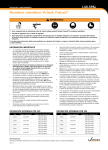
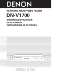
Theory of Operation
The pulse oximeter determines %SpO2 and pulse rate by passing two wavelengths of low
intensity light, one red and one infrared, through body tissue to a photodetector. Information
about wavelength range can be especially useful to clinicians. Wavelength information for this
device can be found in the SpO2 Specifications section of this manual.
Pulse identification is accomplished by using plethysmographic techniques, and oxygen
saturation measurements are determined using spectrophotometric oximetry principles. During
measurement, the signal strength resulting from each light source depends on the color and
thickness of the body tissue, the sensor placement, the intensity of the light sources, and the
absorption of the arterial and venous blood (including the time varying effects of the pulse) in the
body tissues.
1
2
Figure 2.1: Theory of Operation
1
Low intensity Red and Infrared LED light sources
2
Detector
Oximetry processes these signals, separating the time invariant parameters (tissue thickness,
skin color, light intensity, and venous blood) from the time variant parameters (arterial volume
and SpO2) to identify the pulses and calculate functional oxygen saturation. Oxygen saturation
calculations can be performed because blood saturated with oxygen predictably absorbs less red
light than oxygen-depleted blood.
WARNING! Since measurement of SpO2 depends on a pulsating vascular bed, any
condition that restricts blood flow, such as the use of a blood pressure cuff or
extremes in systemic vascular resistance, may cause an inability to determine
accurate SpO2 and pulse rate readings.
WARNING! Under certain clinical conditions, pulse oximeters may display dashes if unable
to display SpO2 and/or pulse rate values. Under these conditions, pulse
oximeters may also display erroneous values. These conditions include, but are
not limited to: patient motion, low perfusion, cardiac arrhythmias, high or low
pulse rates or a combination of the above conditions. Failure of the clinician to
recognize the effects of these conditions on pulse oximeter readings may result
in patient injury.
2-2
Veterinary Handheld Digital Pulse Oximeter Operation Manual
Chapter 2: Intended Use and General Information
Patented Technology
The Handheld Digital Oximeter incorporates patented technology and noise reducing hardware
to enhance the oximeter’s ability to detect pulse amplitude in patients with poor peripheral
perfusion. Blood Pulse Detection Method Using Autocorrelation, patent number 5,558,096, analyzes
a digitized signal, in real time, and compares it with previous pulse data. If similar characteristics
to previous data are recognized, the device confirms a valid pulse. In essence, an individual’s
pulse data is retained and used as a template to accept or reject future pulse signals. Patented
technology, digital signal processing, and a greatly improved signal to noise ratio, provide for
improved performance.
Veterinary Handheld Digital Pulse Oximeter Operation Manual
2-3
Chapter 2: Intended Use and General Information
This page is intentionally left blank.
2-4
Veterinary Handheld Digital Pulse Oximeter Operation Manual
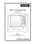
Chapter 3: Controls and Features
Chapter 3: Controls and Features
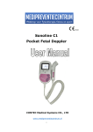
Monitor Front Panel
1
%SpO2
98
80
2
3
6
9
10
BPM
k
B
4
X
n
5
SENSOR
jz
M
13
7
F
12
8
11
o
Figure 3.1: Monitor Controls, and Features
1
Sensor/Printer Connector
The sensor connects here, or an oximetry extension cable can be connected between the
monitor and the sensor. The serial printer or PC communication cable is also connected
here.
2
SpO2 Numeric Display
A number shows the patient’s SpO2 value in percent. Dashes (--) mean the monitor is not
able to calculate the SpO2 value.
3
Pulse Rate Numeric Display
A number shows the patient’s pulse rate value in beats per minute. Dashes (--) mean the
monitor is not able to calculate the pulse rate value.
4
Pulse Strength Bar Graph
The pulse strength bar graph “sweeps” with the patient’s pulse beat. The height of the bar
graph shows the patient’s pulse strength.
5
Sensor Problem Alert Indicator
This indicator lights steadily to inform the operator of an oximeter sensor problem.
6
j Alarm Silence Indicator
This indicator flashes during temporary two-minute alarm silence. The indictor lights
steadily during permanent/indefinite alarm silence.
7
z Artifact Alert Indicator
This indicator informs the operator about the presence of excess artifacts.
8
M Low Battery Indicator
During a Low Battery Attention, this LED is lit and an audible burst of 5 beeps notifies the
user that approximately 30 minutes of battery use remains.
Veterinary Handheld Digital Pulse Oximeter Operation Manual
3-1
Chapter 3: Controls and Features
9
High Priority Alarm LED (red)
This LED flashes twice every second during a high priority condition. This signal indicates
that immediate operator attention is needed.
10
Low Priority Alarm LED (yellow)
This LED indicates a low priority alarm, which lights steadily during a low priority alarm
condition.
11
Line/Power Indicator (green)
This LED lights steadily while external power is applied.
12
IR Printer Output
The Digital Oximeter can transmit data to an optional HP printer via an infrared link through
this port.
13
AC Power Jack
An optional AC power supply connects here.
3-2
Veterinary Handheld Digital Pulse Oximeter Operation Manual
Chapter 3: Controls and Features
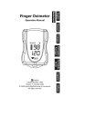
Monitor Operating Keys
98
80
BPM
k
B
3
5
SENSOR
jz
M
F
%SpO2
X
n
4
o
2
1
Figure 3.2: Monitor Operating Keys
1
x ON/OFF Key
Pressing this key turns the monitor ON and OFF.
2
n Up and o Down Arrows
The Up and Down arrow keys are used to adjust the following settings:
• Alarm Limits
• %SpO2/Pulse Rate averaging
• Trend Interval
• Low Priority Alarms Delay
• Alarm Volume
• Pulse Volume
3
B Alarm Silence
Momentarily pressing the Alarm Silence key disables the alarm tone for two (2) minutes.
Pressing and holding the Alarm Silence key for about three (3) seconds disables the alarm
tone indefinitely (until canceled or the monitor is turned off ). To cancel either the indefinite
or the two-minute alarm and alert tone silenced condition, momentarily press the Alarm
Silence key. The Alarm Silenced indicator will turn off.
4
H Alarm Select
Pressing this key cycles through each of the alarm settings.
5
F PRINT/CLEAR Key
Located on the side of the monitor. Pressing this key will send data to the optional IR printer.
Pressing the key again will stop printing. Pressing and holding the Print/Clear key will clear
the trend data.
Veterinary Handheld Digital Pulse Oximeter Operation Manual
3-3
Chapter 3: Controls and Features
This page is intentionally left blank.
3-4
Veterinary Handheld Digital Pulse Oximeter Operation Manual
Chapter 4: Operating Instructions
Chapter 4: Operating Instructions
warning! This device must be used in conjunction with clinical signs and symptoms. This
device is only intended to be an adjunct in patient assessment.
Unpacking the Monitor
1. Carefully remove the monitor and its accessories from the shipping carton. Save the packing
materials in case the monitor must be shipped or stored.
2. Compare the packing list with the supplies and equipment you received to make sure you
have everything you’ll need.
Install the Batteries
The oximeter uses 6 (six) standard “AA” alkaline cells, IEC Type LR6.
To install/replace the batteries:
1. Depress the battery door tab and lift up.
2. Install the negative end of each battery first, compressing the battery terminal spring until
the positive terminal clears the positive tab. Press the battery down into place.
3. Place battery door tabs into the slots of the monitor back panel, depress the door tab, and
press the door into place.
NOTE! If you install disposable batteries, be sure to dispose of them in compliance with
your institution’s guidelines and local ordinances.
NOTE! The unit will hold data for about one and a half minutes with no battery power. This
will insure the safety of trend data during battery replacement.
AC Power
Refer also to Chapter 12: Optional Supplies and Accessories to verify the proper AC power supply for
your application.
NOTE! The AC power supply does not act as a battery charger.
NOTE! Do not plug the monitor into an outlet controlled by a wall switch.
1611
AC power supply 105 - 152 VAC 60Hz
1612
AC power supply 208 - 252 VAC 50/60Hz
1613
AC power supply 90 - 110 VAC 60Hz
NOTE! When using AC power, the Digital Oximeter is a class II device with functional earth.
This earth connection is for device electromagnetic compatibility and does not
provide protection to the patient or user.
NOTE! Intermittent use of AC power will require functional “AA” cells to maintain memory
and keep the oximeter from defaulting to clinician mode from other modes.
Veterinary Handheld Digital Pulse Oximeter Operation Manual
4-1
Chapter 4: Operating Instructions
Attaching the Sensor to the Patient
warning! Prolonged use or the patient’s condition may require changing the sensor site
periodically. Change sensor site and check skin integrity, circulatory status,
and correct alignment at least every 4 hours.
warning! When attaching sensors with Microfoam® tape, do not stretch the tape or
attach the tape too tightly. Tape applied too tightly may cause inaccurate
readings and blisters on the patient’s skin (lack of skin respiration, not heat,
causes the blisters).
Attaching the patient to the monitor requires these steps:
1. Choose the sensor.
2. Check the sensor and oximetry cable.
3. Clean or disinfect the sensor if using the reusable type (Disposable sensors are for singlepatient use and do not require cleaning or disinfecting).
4. Attach the sensor to the patient.
Choosing the Sensor
Choose the appropriate sensor from the following chart.
patient
Small/Medium Animal
up to 60 pounds
Large Animals over
60 pounds
Equine
4-2
site
sensor #/Description
Pinna (ears), Toe Webbing,
Tongue
V1711: Large ‘Y’ Sensor
V1702: Mini ‘Y’ Sensor
V3078: Mini Clip Sensor
Rectum/Tail
V1700: Reflectance Sensor
V1710: Tail Wrap Sensor
Hock, Achilles Tendon, etc.
V1707: Universal ‘C’ Sensor
Pinna (ears), Toe Webbing,
Tongue
V1711: Large ‘Y’ Sensor
V1702: Mini ‘Y’ Sensor
V3078: Mini Clip Sensor
Rectum/Tail
V1700: Reflectance Sensor
V1710: Tail Wrap Sensor
Hock, Achilles Tendon, etc.
V1707: Universal ‘C’ Sensor
Tongue
V1707: Universal ‘C’ Sensor
Veterinary Handheld Digital Pulse Oximeter Operation Manual
Chapter 4: Operating Instructions
Care and Handling of the Sensor
warning! Misuse or improper handling of the sensor and cable could result in damage to
the sensor. This may cause inaccurate readings.
Hold the connector rather than the cable when connecting or disconnecting the sensor to the
device as shown in Figure 4.1.
Cable
Connector
%SpO2
SENSOR
BPM
k
B
j
X
n
o
Figure 4.1: Disconnecting or connecting the sensor.
Do not use excessive force or unnecessary twisting when connecting, disconnecting, storing, or
when using the sensor.
Veterinary Handheld Digital Pulse Oximeter Operation Manual
4-3
Figure 4.2: Attaching the ‘Y’ sensor to the lingual clip
Chapter 4: Operating Instructions
Pulse Oximeter Sensors
NOTE!
2 Please see insert accompanying each sensor for further details.
Large ‘Y’ Sensor
(V1711)
Mini Clip
(V3078)
Mini ‘Y’ Sensor
(V1702)
Figure 4.2: Lingual Sensors
Attach the sensor and clip to the patient’s tongue. Make sure the light source is topside of the
tongue.
Figure 4.3: Attaching the Sensor to the Animal
Reflectance Sensors
Tail Wrap Sensor
(V1710)
Figure 4.4: Reflectance Sensors
Reflectance sensor
(V1700)
For best results while using the tail wrap sensor (V1710), apply to the ventral base of the tail with
the divider positioned centrally. Moisten the fur and parting at the application site or shaving a
small area is required. The sensor works best on medium to large sized patients.
Secure sensor strap.
Tail Clip Sensor
Figure 4.5: Attaching the Sensor to the Animal
For best results while using the reflectance sensor (V1700), apply to the base of the tail. This
sensor can also be used rectally if needed.
When using either of the reflectance sensors, ultrasound gel is recommended to enhance
performance. Fur, dark pigmentation, poor perfusion and movement can affect the sensor’s ability
to obtain accurate readings.
4-4
Veterinary Handheld Digital Pulse Oximeter Operation Manual
Chapter 4: Operating Instructions
Pulse Oximeter Sensor Application Tips
There is some variation depending on the manufacturer, but there are three basic types of pulse
oximeter sensors made for the small animal patient:
• Large and Mini ‘Y’ sensors
• Mini Clip sensor
• ‘C’ sensor (may also be used on large animals)
• Tail Wrap sensor
• Reflectance sensor
It is very important to have a variety of sensors in order to monitor the majority of the small
animal patients. It is also important to select the proper sensor for animals based on their size,
color, fur type, medical condition, and type of procedure.
Testing Sensor Function
1. To test the large and mini ‘Y’ sensor functions, turn on the monitor with the lingual sensor
attached. View the sensor to make sure a red light is being emitted, then place the sensor on
a small finger (without nail polish). Rest the hand with the sensor on it on a table to minimize
motion. Note that in most cases the red light should be shining in the same direction as
the overhead or surgical lights. It is important that the light receptor is shielded in order to
avoid interference from ambient light. Once placed on a patient site, the red light should
be shining continuously. In some cases a blinking light indicates that the tissue thickness
is either too thin or thick. Once the sensor is placed properly, both the SpO2 and pulse rate
should appear in a short period of time (10-15 seconds).
2. Testing the ‘C’ sensor is performed in the same manner. This is a stronger sensor and can
be used with greater tissue thickness.
3. Testing the tail wrap and reflectance sensors are performed in the same manner, but it
should be pressed between thumb and index finger or into the palm of your hand.
Primary Applications for Sensors
Large and Mini ‘Y’ Sensor and Mini Clip Sensor
• The primary application site is the tongue for most animals. On cats and small dogs, fold
the tongue like a taco or use a wet gauze pad of single thickness folded over the tongue,
and then place the sensor over the gauze.
• Other sites include the prepuce or vulva of larger dogs, the achilles tendon of a cat or small
dog, ears, or toe webbing.
C Sensor
• For cats and small breed dogs, place the sensor on the thigh, metatarsal or metacarpal, or
hock near the saphenous vein.
• For larger breed dogs, place the sensor over the Achilles tendon, tongue, prepuce or vulva,
or through toe webbing.
• It may be necessary to wet and part the fur with water in order to get the sensor closer to
the skin of the patient.
• For large animals (e.g. horses), place the sensor on the tongue.
Veterinary Handheld Digital Pulse Oximeter Operation Manual
4-5
Chapter 4: Operating Instructions
Tail Wrap Sensor and Reflectance Sensor
• In most animals, wet and part the fur at the ventral tail base and use the straps on the tail
wrap to hold the tail wrap sensor in place.
• When using the reflectance sensor, wet and part the fur at the ventral tail base and use
non-adhesive tape to hold the sensor in place. The reflectance sensor may be used rectally
if the patient has a small or no tail.
• It may be necessary to shave a small spot on the ventral tail base in patients with a thick
undercoat, such as a Husky.
Limitations
Experience will quickly tell you which probes work best under different conditions. Fur, dark
pigmentation, poor perfusion, and movement can all affect the sensors ability to obtain accurate
readings. Well-perfused sites with little or no hair are preferable. It is also important to note that
some anesthetic drugs, such as Xylazine (Rompun), Acepromazine, or Medetomidine (Domitor)
can affect peripheral pulse pressures causing very weak pulsations. All pulse oximeters require
a good quality pulse to work properly. Other drugs, such as ketamine, can cause the tongue to
twitch, limiting the use of a lingual clip on that site.
Checking the Sensor and Oximetry Cable
Follow these instructions each time before you attach the sensor to the patient. This helps ensure
the sensor and oximetry cable are working properly.
warning! Using a damaged sensor may cause inaccurate readings. Inspect each sensor.
If a sensor appears damaged, do not use it. Use another sensor or contact your
authorized repair center for help.
warning! Using a damaged oximetry cable may cause inaccurate readings. Inspect the
oximetry cable. If the oximetry cable appears damaged, do not use it. Contact
your authorized repair center for help.
1. Carefully inspect the sensor to make sure it does not appear damaged.
2. If using the oximetry cable, carefully inspect the oximetry cable to make sure it does not
appear damaged.
3. If using the oximetry cable:
a. If the sensor is not already connected to the oximetry cable, connect the sensor to the
oximetry cable. Push the connectors together firmly and close the latch to secure the
connectors.
b. If the oximetry cable is not already connected to the monitor, connect the oximetry cable
to the monitor. Push the connector firmly into the monitor.
4. If not using the oximetry cable, connect the sensor to the monitor. Push the connector firmly
into the monitor.
5. If the monitor is not already on, press the x key to turn on the monitor.
warning! If any of the integrity checks fail, do not attempt to monitor the patient. Use
another sensor or oximetry cable, or contact the equipment dealer for help if
necessary.
4-6
Veterinary Handheld Digital Pulse Oximeter Operation Manual
Chapter 4: Operating Instructions
6. Before the sensor is attached to the patient, check the integrity of the sensor, oximetry cable,
and oximeter as follows:
a. Make sure the red light in the sensor is illuminated.
NOTE! Obstructions or dirt on the sensor’s red light or detector may cause the checks to
fail. Make sure there are no obstructions and the sensor is clean.
7. You are now ready to attach the sensor to the patient.
Cleaning or Disinfecting the Sensors
Clean or disinfect reusable sensors before attaching to a new patient.
warning! Do not autoclave, ethylene oxide sterilize, or immerse the sensors in liquid.
caution! Unplug the sensor from the monitor before cleaning or disinfecting.
Clean the sensor with a soft cloth moistened in water or a mild soap solution. To disinfect the
sensor, wipe the sensor with isopropyl alcohol.
Turning On the Monitor
%SpO2
98
80
1
2
3
BPM
k
B
X
n
o
Figure 4.6: SpO2, pulse rate, and pulse strength bar graph.
1
Patient’s SpO2 Shown Here
2
Patient’s Pulse Shown Here
3
Patient’s Pulse Strength Shown Here
1. To turn on the monitor, press the x key. When turned ON, the monitor does the following:
• The top segment of the pulse strength bar graph illuminates.
• The monitor's software revision is momentarily displayed.
• The patient number is momentarily displayed.
WARNING! Verify that all LEDs (light emitting diodes) on the display light up upon startup
of the device.
Veterinary Handheld Digital Pulse Oximeter Operation Manual
4-7
Chapter 4: Operating Instructions
2. The monitor has two averaging settings for %SpO2 and pulse rate. To change the averaging
setting, press and hold the n Up Arrow while turning on the monitor. This will set the
%SpO2 and pulse rate averaging to 16/16. Press and hold the o Down Arrow while turning
on the monitor to set the %SpO2 and pulse rate averaging to 4/8.
NOTE! Increasing or decreasing the averaging setting has no effect on the data update
rate.
NOTE! SpO2 averaging is the number of pulse beats over which the SpO2 value is averaged;
pulse averaging is the number of seconds over which the pulse value is averaged.
High Priority Alarms
A high priority alarm warns you about an abnormal patient condition.
A high priority alarm is activated when:
• the patient’s SpO2 reading matches or exceeds the SpO2 alarm range.
• the patient’s pulse rate reading matches or exceeds the pulse rate alarm range.
%SpO2
98
20
1
BPM
2
k
B
X
n
o
Figure 4.7: Alarm Example
1
During a high priority alarm, the numbers flash that correspond to the
alarm.
2
The high priority alarm LED flashes.
a. The alarm tone sounds, if not silenced. The high priority alarm tone consists of 3 short
bursts, a pause, followed by 2 more short bursts.
Note: The alarm tone does not sound if the Alarm Silenced indicator is on or flashing.
NOTE! Both SpO2 and pulse rate numbers will flash if both readings match or exceed their
alarm range.
4-8
Veterinary Handheld Digital Pulse Oximeter Operation Manual
Chapter 4: Operating Instructions
Low Priority Alarms
A low priority alarm warns you about an abnormal monitor condition.
A low priority alarm is activated when the:
• Sensor is not connected to the monitor.
• Sensor is not attached to the patient.
• Sensor is not properly attached to the patient.
• Signal contains artifact.
%SpO2
2
---BPM
3
SENSOR
z
k
B
1
X
n
o
Figure 4.8: Alert Example
1
During a low priority alarm, the SENSOR or Artifact indicator
illuminates.
2
During a low priority alarm, the monitor cannot measure the patients
SpO2 or pulse rate. Dashes are displayed.
3
The Low Priority LED lights steadily and the low priority alarm tone
sounds, if not silenced. The low priority alarm tone consists of 2 long
bursts.
Note: The alert tone does not sound if the Alarm Silenced indicator is on or flashing.
warning! While SENSOR is lit, the monitor cannot measure the patient’s SpO2 or pulse
rate. If the Artifact indicator is lit, the patient’s readings may not reliably
reflect his/her actual condition. The patient’s condition should be checked
immediately. After checking the patient’s condition, correct the SENSOR or
Artifact low priority alarm. See Correcting the SENSOR/Artifact Alert in the
Troubleshooting section for help.
Veterinary Handheld Digital Pulse Oximeter Operation Manual
4-9
Chapter 4: Operating Instructions
Low Battery Indicator
%SpO2
98
80
BPM
2
M
k
B
1
X
n
o
Figure 4.9: Low Battery Attention
1
The Low Battery indicator (red) lights up steadily until the batteries are
replaced.
2
The Low Priority Alarm LED (yellow) indicator lights up steadily and the
low battery tone sounds.
warning! When the LOW BATTERY INDICATOR is illuminated, you must immediately
replace the monitor’s batteries. Otherwise, the monitor turns itself off about 30
minutes after the low battery indicator illuminates.
NOTE! The Alarm Silence key cannot disable the Low Battery audible tone.
During a LOW BATTERY ATTENTION:
• The Low Battery indicator M lights up steadily.
• The low priority alarm LED lights up steadily.
• A series of five high pitch “beeps” will sound every minute until the batteries are replaced.
4-10
Veterinary Handheld Digital Pulse Oximeter Operation Manual
Chapter 4: Operating Instructions
High and Low Priority Alarm Summary
display indicator
led indicator
High Priority
Alarms
type
Numbers corresponding
to violated alarm will flash
(SpO2 and pulse rate)
High priority alarm
LED (red) flashes
Overrides pulse
beeps
effects
Alarm tone
sounds
audio
Low Priority
Alarms
Attention indicators light
up steadily: SENSOR or
Artifact
Low priority alarm
LED (yellow) lights
up steadily
Overrides pulse
beeps
Low priority
alarm tone
sounds
Information
Signal
Low battery indicator
Low priority alarm
LED lights steady
Overrides all
audio
(one shot)
5 beeps that
occur once every
30 seconds
Turning Off the Monitor
Turn off the monitor when you are not monitoring a patient.
To turn off the monitor, press the x key.
Checking the Monitor’s Performance
Pulse oximeters do not require user calibration. If checking the function of the device is desired,
an optional Oximeter Patient Simulator (Smiths Medical catalog number 1606) is available as
an accessory. The simulator attaches to the oximeter in place of the sensor or oximetry cable.
It provides a known SpO2 and pulse rate signal to the oximeter. This allows the oximeter’s
performance to be checked.
NOTE! The 1606 Oximeter Patient Simulator does not calibrate the monitor; the monitor
does not require calibration. The 1606 provides a known SpO2 and pulse rate to the
monitor that allows you to check the monitor’s performance.
NOTE! The 1606 Oximeter Patient Simulator cannot be used to assess the accuracy of a
pulse oximeter and/or sensor.
NOTE!
2 Follow the instructions included with the Oximeter Patient Simulator.
Veterinary Handheld Digital Pulse Oximeter Operation Manual
4-11
Chapter 4: Operating Instructions
This page is intentionally left blank.
4-12
Veterinary Handheld Digital Pulse Oximeter Operation Manual
Chapter 5: Changing the Monitor’s Settings
Chapter 5: Changing the Monitor’s Settings
Silencing Alarm Tones
The high and low priority alarm tones can be silenced for two minutes or indefinitely (until
canceled or until the monitor is turned off ).
1. To silence the alarm tones for two minutes, momentarily press the Alarm Silence key B.
If alarms were already silenced, you must press the Alarm Silence key B again. The alarm
silence indicator j flashes during the two-minute time-out.
2. To silence the alarm and alert tones indefinitely, press and hold the Alarm Silence key B
for about three seconds. The alarm silence indicator j lights steady while alarms are
silenced indefinitely.
3. To cancel either the indefinite or the two-minute alarm tone silenced condition, momentarily
press Alarm Silence key B the alarm silenced indicator turns off.
Changing the Pulse Beep Volume
A “beep” tone sounds with each pulse beat. The volume of the “beep” can be adjusted to fifteen
(15) settings and off.
To adjust the volume to the ‘off’ setting, press and hold the o Down Arrow. From the ‘off’ setting,
set the volume by pressing the n Up Arrow. The volume is increased/decreased with each key
press.
Changing the Alarm Limits
Each measurement, SpO2 and Pulse Rate, has a high and low alarm limit setting.
Press the Alarm Select key H until the alarm limit you want to change is shown, then press
the Up or Down key n or o to increase or decrease the setting.
alarm sel key
press
First Press.
Second press.
Third press.
Fourth press.
Fifth press.
display
--- KI
85
Lo
Ki 155
Lo
50
97
74
alarm limit
- - - = High SpO2 alarm limit (Example only.)
85 = Low SpO2 alarm limit (Example only.)
155 = High pulse rate alarm limit (Example only.)
50 = Low pulse rate alarm limit (Example only.)
97 = SpO2 measurement (Example only.)
74 = Pulse rate measurement (Example only.)
WARNING! Be aware of alarm limits of similar units in the same area when adjusting alarm
limits of this device to avoid confusion.
Veterinary Handheld Digital Pulse Oximeter Operation Manual
5-1
Chapter 5: Changing the Monitor’s Settings
NOTE! “ – – – ” in the alarm limit display means the limit is set to off.
NOTE! Alarm limits are non-overlapping. You cannot set the high alarm equal to or lower
than the low alarm and you cannot set the low alarm equal to or higher than the
high alarm.
NOTE! Alarm limits are retained through power cycles, with the exception of the following
note.
NOTE! If either the low or high SpO2 alarm limit is set below 80%, they will reset to 85% or
higher when the monitor is next powered on.
NOTE! While setting alarm limits, if no keys are pressed for twenty seconds, the alarm
limit setting mode is exited and the SpO2 and pulse rate measurements are shown.
Changes are saved.
NOTE! Alarms are not active while setting alarm limits; however, alarms are active as soon
as you exit the alarm limit setting mode.
NOTE! The alarm actions occur for each violated alarm, even if more than one alarm is
violated at the same time.
NOTE! Alarms may be tested while the monitor is in use by setting alarm limits such that
the measured parameter is outside alarm limits. Return limits to the required
settings after testing.
Setup Mode
Setup mode allows the user to change the settings for the following options:
• Trend Data Storage Interval, see Chapter 6, Patient Numbers & Trend Data, for descriptions
• Alarm Volume
• Low Priority Alarms Delay
• Permanent Silence Disable
To enter Setup Mode, press and hold the
Z
Alarm Select key while turning the monitor on.
Alarm Volume
The volume of the alarm tone can be adjusted through a range of 13 settings. The alarm volume
cannot be disabled through the Setup Mode.
To adjust the volume of the alarm tone, press the Z Alarm Select key twice upon entering
Setup Mode. The display will show AL 3 and an audible alarm tone will sound. To increase the
volume, press the n Up Arrow. The alarm volume setting ranges from 3 to 15.
5-2
Veterinary Handheld Digital Pulse Oximeter Operation Manual
Chapter 5: Changing the Monitor’s Settings
Low Priority Alarms Delay
The Low Priority Alarms Delay feature delays the audible low priority alarm during a SpO2
searching or artifact event for a specified amount of time.
To set the delay interval, press the Z Alarm Select key three times upon entering Setup Mode.
The display will show dL OFF . To adjust the delay interval, press the n Up Arrow. The delay
interval choices are OFF, 15, 30, or 45 seconds.
Permanent Silence Disable
Alarm audio can be disabled by using the B Alarm Silence key, for 2 minutes or permanently as
previously described in this chapter.
Permanent silence disable in the Setup Mode will allow the user to set the alarm audio
preferences (2 minute silence or permanent silence).
1. To set the alarm audio preferences, press the
entering Setup Mode.
Z
Alarm Select key four times upon
2. The display will show Pr Aud if the monitor has been set to allow the user to
permanently disable the alarm audio.
3. To only permit 2 minute alarm silence, press the o Down Arrow. The display will show
2 Aud.
NOTE! If set to 2-minute alarm silence, the alarm audio can only be disabled for 2 minutes.
Veterinary Handheld Digital Pulse Oximeter Operation Manual
5-3
Chapter 5: Changing the Monitor’s Settings
This page is intentionally left blank
5-4
Veterinary Handheld Digital Pulse Oximeter Operation Manual
Chapter 6: Patient Numbers and Trend Data
Chapter 6: Patient Numbers and Trend Data
Description
Whenever the monitor is on, it stores one SpO2 and one pulse rate reading every four (4) to thirty
(30) seconds. These intervals are adjustable as described later in this chapter. The stored readings
are called trend data. The monitor remembers trend data for up to 99 patients and 90 hours of
run-time.
Trend data is saved for each patient number. When you turn on the monitor, the patient number
is automatically incremented and displayed during the power-up sequence. If valid trend data
was collected from the previous patient, the patient number is incremented. If no valid trend
data was collected from the previous patient, the patient number is displayed only and is not
incremented.
Trend data for all patients can be printed on the optional printer.
Trend data will be preserved for about one and a half minutes, without battery power, allowing
battery replacement without losing trend data.
NOTE! See Printer section for information on printing trend data.
Incrementing the Patient Number
The patient number will be advanced at power up if any patient data has been collected during
the previous on time.
Adjusting the Trend Storage Interval
1. Enter Setup Mode: press and hold the
Z
Alarm Select key while turning the monitor on.
2. Press the Z Alarm Select key once. The trend storage interval will appear on the display,
showing the default interval of 30 seconds.
3. Use the n Up or o Down Arrow keys to increase or decrease the trend storage interval. The
interval range is 4 seconds to 30 seconds.
sample Interval (Seconds)
Run-Time (Hours)
4
12
5
17
8
24
10
34
20
68
30
90
Clearing Trend Data
To clear trends, press and hold the PRINT F key for 15 seconds. The [{r message on the
7-segment displays will flash to indicate that the trend clear is about to happen.
Veterinary Handheld Digital Pulse Oximeter Operation Manual
6-1
Chapter 6: Patient Numbers and Trend Data
This page is intentionally left blank.
6-2
Veterinary Handheld Digital Pulse Oximeter Operation Manual
Chapter 7: Printer
Chapter 7: Printer
Description
Data can be printed in either data log, or trend data mode. In the trend data mode, up to 90 hours
of previously stored data, collected from 1 to 99 patients, is printed. Data log prints real time data.
A maximum of twenty-four (24) characters will be printed on one line. Data will be printed at a
rate of one line every 5 seconds.
TREND
PN
01
H :M :S
00:00:00
00:00:30
PN
02
H :M :S
00:00:00
00:00:30
SpO2 BPM
96% 120bpm
97% 119bpm
SpO2 BPM
--% 120bpm
97% 119bpm
Figure 7.1: Sample Trend Printout
DATA LOG
SpO2
98%
97%
BPM
70bpm
72bpm
Figure 7.2: Sample Data Log
What You’ll Need for Printing
You’ll need these items to print trend printouts:
• Digital Oximeter.
• Optional infrared HP 82240B printer. (Trend and Data Log Print outs), part #8411
• Accessories required for the printer, such as paper, can be purchased from an authorized
distributor.
warning! When connecting this monitor to any instrument, verify proper operation
before clinical use. Refer to the instrument’s user manual for full instructions.
Accessory equipment connected to the monitor’s data interface must be
certified according to the respective IEC standards, i.e., IEC 60950 for data
processing equipment or IEC 601-1 for electromedical equipment. All
combinations of equipment must be in compliance with IEC 601-1-1 systems
requirements. Anyone connecting additional equipment to the signal input
port or the signal output port configures a medical system, and, therefore,
is responsible that the system complies with the requirements of the system
standard IEC 601-1-1.
Veterinary Handheld Digital Pulse Oximeter Operation Manual
7-1
Chapter 7: Printer
Trend Printouts
Collecting Trend Data
Whenever the monitor is on, it stores one SpO2 and one pulse rate reading every four (4) to thirty
(30) seconds. The stored readings are called trend data. The monitor remembers trend data for
up to 99 patients and 90 hours of run-time. The trend data can then be printed at any time on the
optional printer.
Trend data is saved for each patient number. When you turn on the monitor, if valid trend data
was collected from the previous patient, the patient number is automatically incremented. If no
valid trend data was collected from the previous patient, the patient number is displayed only,
and is not incremented.
Follow these steps for trend data printouts:
1. Turn on the printer.
2. Disconnect the SpO2 sensor from the patient and to the oximeter as previously described.
3. Turn on the monitor.
4. Align the IR sensor on the Digital Oximeter with the IR sensor on the printer as shown in
figure 7-1 or, as described in Chapter 9: PC Communication Setup.
5. Depress the F print key (not at start up). The oximeter prints the SpO2 and pulse rate
measurements as shown in the sample printout.
6. Dashes indicate invalid or unavailable data (for example, the patient’s finger was removed
from the SpO2 sensor).
7. Depress the
F
print key to quit printing, or the unit will print all stored trend data.
NOTE! If unexpected characters or question marks are printed, turn the monitor off and on
to reset the printer.
Data log
The data log is a real time printout of patient data. Data will be printed at a rate of one line every
5 seconds.
Follow these steps for data log printout:
1. Turn on the printer.
2. Connect the sensor to the monitor and the patient.
3. Align the IR sensor on the Digital Oximeter with the IR sensor on the printer.
4. Press the print
5. Press the print
F
F
key to begin printing.
key again to stop printing.
2
%SpO
Q BPM
D
O2
EN
Sp
TR 01
PN :M :S
H
BP
M
B n
o
Figure 7.1: Aligning the Printer and Oximeter
7-2
Veterinary Handheld Digital Pulse Oximeter Operation Manual
Chapter 8: PC Communication Setup
Chapter 8: PC Communication Setup
Description
The device will send out Trend Data through the sensor connector when the sensor / patient
cable is not plugged in. An additional cable is used to connect the device to a serial printer or PC
computer. The following items will be needed:
1. Printer Cable
2. DB-9 Null Modem Cable
3. DB-9 Printer Connector
PC Communication Setup
1. Power up the monitor.
2. Connect the printer communication cable to the monitor.
3. Set up the communication software to accept the following RS-232 data format :
• Data Type: ASCII
• Data Format: 9600 baud, 1 start bit, 8 data bits, 1 stop bit, no parity
4. Connect the standard RS-232 null modem cable’s DB-9 connector to the mating connector of
the printer cable.
5. Connect the standard RS-232 null modem cable’s DB connector to the mating connector on
the PC.
NOTE! The DB-9 null modem cable is an industry standard RS-232 modem cable.
Printer
Cable
DB9 Null
Modem Cable
%SpO2
BPM
k
B
X
n
o
DB9 PC
Figure 8.1: PC Communication Setup
Veterinary Handheld Digital Pulse Oximeter Operation Manual
8-1
Chapter 8: PC Communication Setup
This page is intentionally left blank.
8-2
Veterinary Handheld Digital Pulse Oximeter Operation Manual
Chapter 9: Maintenance
Chapter 9: Maintenance
Schedule of Maintenance
maintain this item
how often
by doing this
Battery
When Low Battery
Attention indicator is
flashing, and/or audible
battery indicator
sounds.
Follow the instructions for installing the batteries.
Disinfecting the reusable
sensor.
Before attaching the
sensor to the patient.
Follow the instructions for cleaning the reusable
sensor.
Disinfecting the monitor.
When necessary.
1. Remove the batteries from the unit.
Note: Print trend data before cleaning.
Trend data will be lost if batteries are
disconnected more than one and a half
minutes.
2. Wipe the surfaces of the monitor with a soft,
clean cloth dampened in isopropyl alcohol.
Use only a cloth that is dampened, not wet.
CAUTION! Do not allow isopropyl alcohol
or water to enter any of the
openings on the monitor.
Evidence that liquid has been
allowed to enter the monitor
voids the warranty.
Storage
Whenever possible, the monitor should be stored at room temperature in a dry environment.
If it is necessary to store the monitor for an extended period of time, the unit should be packed
in its original shipping container. Storing the monitor for a long period of time may degrade the
battery capacity. Batteries should be removed from the monitor before storing.
Storage specifications are as follows:
Temperature:
Relative Humidity:
-40oC to +75oC (-40oF to +167oF)
10% to 95% (noncondensing)
Veterinary Handheld Digital Pulse Oximeter Operation Manual
9-1
Chapter 9: Maintenance
This page is intentionally left blank.
9-2
Veterinary Handheld Digital Pulse Oximeter Operation Manual
Chapter 10: Troubleshooting
Chapter 10: Troubleshooting
problem
No pulse shown on
the bargraph.
Pulse rate is erratic,
intermittent, or
incorrect.
possible cause
corrective action
Patient cable or sensor is
disconnected from the
oximeter.
Check sensor connections to the patient cable and to
the oximeter.
Sensor is incorrectly
positioned on the patient.
Reposition the sensor.
Poor patient perfusion.
Reposition the sensor.
Defective sensor or patient
cable.
Try a new sensor or contact your authorized repair
center for help.
Sensor incorrectly
positioned.
Reposition the sensor.
Patient motion
Patient must remain still to obtain an accurate
measurement.
Poor patient perfusion.
SpO2 value is
erratic, intermittent, Patient motion.
or incorrect.
Reposition the sensor
The oximeter
doesn’t turn on.
Batteries weak.
Replace the batteries.
Batteries not installed
or batteries incorrectly
installed.
Ensure the batteries are installed correctly.
The oximeter turns
off unexpectedly.
Batteries are weak or dead.
Replace the batteries.
No printout on
optional printer.
Batteries are weak.
Replace the batteries.
Batteries are not properly
installed.
Ensure the batteries are installed properly.
No trends in memory.
Take trend data.
Sensor must be
disconnected for trend
data printout.
Disconnect the sensor.
Printer interface
malfunction.
Contact Smiths Medical PM, Inc. Veterinary Clinical
Support for help.
Printer and oximeter
alignment incorrect (for
infrared printers)
Realign printer and oximeter.
E00
ROM Error
Contact Smiths Medical PM, Inc. Veterinary Clinical
Support or your local distributor
E01
RAM Error
Contact Smiths Medical PM, Inc. Veterinary Clinical
Support or your local distributor
Sensor
Patient cable or sensor is
disconnected from the
oximeter.
Check sensor connections to the patient cable and to
the oximeter.
Sensor is incorrectly
positioned on the patient.
Reposition the sensor.
Poor patient perfusion.
Reposition the sensor.
Defective sensor or patient
cable
Try a new sensor or contact Smiths Medical PM, Inc.
Veterinary Clinical Support for help.
Patient motion
Patient must remain still to obtain an accurate
measurement.
Artifact
Patient must remain still to obtain an accurate
measurement.
Veterinary Handheld Digital Pulse Oximeter Operation Manual
10-1
Chapter 10: Troubleshooting
EMI Interference
CAUTION! This device has been tested and found to comply within the limits for medical
devices to IEC 601-1-2:1993, EN 60601-1-2:1994, and the Medical Device
Directive 93/42/EEC. These limits are designed to provide reasonable protection
against harmful interference in a typical medical installation. However,
because of the proliferation of radio-frequency transmitting equipment and
other sources of electrical noise in the heath-care and home environments (for
example, cellular phone, mobile two-way radios, electrical appliances), it is
possible that high levels of such interference due to close proximity or strength
of a source, may result in disruption of performance of this device.
The monitor is designed for use in environments in which the signal can be obscured by
electromagnetic interference. During such interference, measurements may seem inappropriate
or the monitor may not operate correctly.
The monitor generates, uses, and can radiate radio frequency energy and, if not installed and
used in accordance with these instructions, may cause harmful interference with other devices
in the vicinity. Disruption may be evidenced by erratic readings, cessation of operation, or other
incorrect function. If this occurs, the site of use should be surveyed to determine the source of this
disruption, and actions taken to eliminate the source:
• Turn equipment in the vicinity off and on to isolate the offending equipment.
• Reorient or relocate the other receiving device.
• Increase the separation between the interfering equipment and this equipment.
If assistance is required, contact the Smiths Medical PM, Inc. Clinical Support Department or your
local representative.
10-2
Veterinary Handheld Digital Pulse Oximeter Operation Manual
Chapter 11: Optional Supplies and Accessories
Chapter 11: Optional Supplies and Accessories
cat. no
description
qty
1606
Simulator & Cable , Oximeter, 1.5m (5 ft)
each
1611
Battery Bypass 105-125 VAC 60Hz (domestic)
each
1612
Battery Bypass 208-252 VAC 50/60Hz (international)
each
1613
Battery Bypass 90-110 VAC 60Hz (Japan)
each
V1700
Sensor, Oximetry, reflectance (R/E, Small/Medium)
each
V1702
Mini ‘Y’ Clip
each
V1707
Sensor, Oximetry, Universal ‘C’
each
V1709
Clip, Replacement for use with V1707
V1710
Tail Wrap Sensor
each
V1711
Large ‘Y’ Clip
each
V1896
Manual, Operation Handheld Digital Pulse Oximeter
each
V3078
Mini Clip
each
3311
Oximetry Cable 1.5m (5 ft)
each
3339
PC Adapter Cable
each
3350
Cable, Printer Interface
each
3419
Protective Rubber Boot with Carrying Strap
each
8411
Infrared HP Printer MCP8850B
each
8416
Printer Paper
4/pkg
10/pkg
Ordering Information
For ordering information, contact your local distributor or the Smiths Medical PM, Inc. Veterinary
Clinical Support.
Smiths Medical PM, Inc.
N7W22025 Johnson Drive
Waukesha, Wisconsin 53186-1856
Telehone: (262) 513-8500
Toll-Free: (888) 745-6562
Fax: (262) 513-9069
Website: www.surgivet.com
Veterinary Handheld Digital Pulse Oximeter Operation Manual
11-1
Chapter 11: Optional Supplies and Accessories
This page is intentionally left blank.
11-2
Veterinary Handheld Digital Pulse Oximeter Operation Manual
Chapter 12: Specifications
Chapter 12: Specifications
Equipment Classification
Type of Protection Against Electric shock:
Internally Powered
Mode of operation:
Continuous
Degree of Protection Against ingress of
Liquids:
IPX1, drip proof
Degree of Mobility:
Portable
Degree of Protection Against Electric Shock:
Type CF
Safety Requirements:
EN60601-1: 1990
Displays, Indicators, & Keys
SpO2:
LED numeric display, 7.62 mm (0.30 inches) high
Pulse Rate:
LED numeric display, 7.62 mm (0.30 inches) high
Pulse Strength: Logarithmically scaled 8-segment LED bargraph
Indicators:
M
Low Battery indicator
SENSOR Sensor alert indicator
j
z
LEDs:
Alarm Silence
Artifact
High Priority (red)
Low Priority (yellow)
Line Power (green)
Keys:
x
F
B
On/Off key
PRINT key
Alarm Silence
n Up Arrow
o Down Arrow
Z Alarm Select
Veterinary Handheld Digital Pulse Oximeter Operation Manual
12-1
Chapter 12: Specifications
SpO2
Range:
0 - 99% Functional SpO2 (1% increments)
1
Accuracy :
±2 at 70 - 99%
±3 at 50 - 69%
Alarms:
Low: 50%-99% and OFF
High: 50%-99% and OFF
Steps: 1%
Factory Defaults:
Low: OFF
High: OFF
Averaging:
4/8/16 pulse beat average (selectable)
Display Response:
The display is to functional saturation. The pulse strength bar graph is
not proportional to pulse volume.
Display Update Rate:
1 Hz (SpO2); 60 Hz (pulse strength)
Calibration:
Factory calibrated over the range of 50% to 100% SpO2 using human
blood samples to functional saturation. Test methods available upon
request. No in-service calibration is required.
Sensor:
Red
660nm, 2.0 mW
Infrared 905 nm, 2.0 - 2.4 mW
1
Because pulse oximeter measurements are statistically distributed, only about two-thirds of
pulse oximeter equipment measurements can be expected to fall within the ARMS of the value
measured by the CO-oximeter. The 3402 has been validated in human desaturation studies on
10 adult volunteers that did not have health problems and were non-smokers. The study was
conducted at oxygen concentrations evenly distributed over an SaO2 range of 50 to 100%.
Pulse Rate
Range:
20-350 bpm (1 bpm increments)
Accuracy:
±1 beat or 2%, whichever is greater
Alarms:
Low: 5-350 bpm and OFF
High: 5-350 bpm and OFF
Steps: 5 bpm
Factory Defaults:
Low: OFF
High: OFF
Averaging:
8 or 16 second average (selectable)
Display Update Rate:
1 Hz
Audible Alarm Indicators
Audible alarm with user-adjustable volume and two minute or indefinite alarm silence.
Alarm Volume:
45dBA to 85 dBA at 1 meter distance (adjustable)
Trend Storage Interval
4 to 30 seconds (selectable)
Default:
30 seconds
Steps:
1 second
12-2
Veterinary Handheld Digital Pulse Oximeter Operation Manual
Chapter 12: Specifications
Power Requirements
AC Power supplies:
1611
AC power supply 105-125VAC 60Hz
1612
AC power supply 208-252VAC 50/60Hz
1613
AC power supply 90-110VAC 60Hz
Or six standard “AA” alkaline cells (IEC Type LR6)
Battery Life
Alkaline Cells: 24 hours with no printing.
Dimensions
Width:
69.85mm (2.75 inches)
Height:
167.64mm (6.6 inches)
Depth:
36.322mm (1.43 inches)
Weight:
595 grams (1lb. 5 ounces) with batteries and optional boot
Environmental Specifications
Operating Temp.:
0 to 55° C (32 to 131° F)
Storage Temp.:
-40 to +75° C (-40 to +167° F)
Relative Humidity:
15 to 95% (operating), non-condensing
10 to 95% (storage), non-condensing
Veterinary Handheld Digital Pulse Oximeter Operation Manual
12-3
Chapter 12: Specifications
This page is intentionally left blank.
12-4
Veterinary Handheld Digital Pulse Oximeter Operation Manual
Appendix A: Guidance and Manufacturer’s Declaration
Appendix A: Guidance and Manufacturer’s Declaration
Guidance and Manufacturer’s Declaration
The V3402 pulse oximeter is intended for use in the electromagnetic environment specified in the
tables within this appendix.
NOTE! The customer or user of the V3402 pulse oximeter should ensure that it is used in
such an environment.
Electromagnetic Emissions - Emissions Test
EMISSIONS TEST
COMPLIANCE
ELECTROMAGNETIC ENVIRONMENT GUIDANCE
RF emissions
CISPR 11
Group 1
The V3402 pulse oximeter uses RF energy only for its internal
function. Therefore, its RF emissions are very low and are not
likely to cause any interference in nearby electronic equipment.
RF emissions
CISPR 11
Class B
Harmonic emissions
IEC 61000-3-2
NA
Voltage fluctuations/
flicker emissions
IEC 61000-3-3
NA
The V3402 pulse oximeter is suitable for use in all
establishments, including:
• Domestic establishments.
• Establishments directly connected to the public lowvoltage power supply network that supplies buildings
used for domestic purposes.
Electromagnetic Emissions – Immunity
IMMUNITY
ELECTROMAGNETIC ENVIRONMENT
GUIDANCE
Electrostatic discharge (ESD) IEC 60601 TEST LEVEL Floors should be made of:
IEC 61000-4-2
• Wood
• ± 6 kV contact
• Concrete
• ± 8 kV air
• Ceramic tile
COMPLIANCE LEVEL
If floors are covered with synthetic material, the
• ± 6 kV contact relative humidity should be at least 30%.
• ± 8 kV air
Veterinary Handheld Digital Pulse Oximeter Operation Manual
A-1
Appendix A: Guidance and Manufacturer’s Declaration
IMMUNITY
Electrical fast transient/burst
IEC 61000-4-4
ELECTROMAGNETIC ENVIRONMENT
GUIDANCE
IEC 60601 TEST LEVEL A.C. Mains power voltage should be the typical
• ±0.5 kV to ±2 kV for quality of a:
power supply lines.
• ±0.25 kV to ±1 kV
for I/O lines.
• Commercial environment.
• Hospital environment.
COMPLIANCE LEVEL
• ±0.5 kV to ±2 kV for
power supply lines.
• ±0.25 kV to ±1 kV
for I/O lines.
Surge
IEC 61000-4-5
IEC 60601 TEST LEVEL
• ±1 kV differential
mode
• ±2 kV common
mode
COMPLIANCE LEVEL
• ±1 kV differential
mode
• ±2 kV common
mode
Voltage dips, short
interruptions, and voltage
variations on power supply
input lines
IEC 61000-4-11
IEC 60601 TEST LEVEL
• <5% UT (>95% dip
in UT) for 0.5 cycle.
• <40% UT (>60% dip
in UT) for 5 cycles.
• <70% UT (>30% dip
in UT) for 25 cycles.
• <5% UT (>95% dip
in UT) for 5 seconds.
COMPLIANCE LEVEL
• <5% UT (>95% dip
in UT) for 0.5 cycle.
• <40% UT (>60% dip
in UT) for 5 cycles.
• <70% UT (>30% dip
in UT) for 25 cycles.
• <5% UT (>95% dip
in UT) for 5 seconds.
Note: UT is the A.C. mains voltage prior to application of the test level.
A-2
Veterinary Handheld Digital Pulse Oximeter Operation Manual
Appendix A: Guidance and Manufacturer’s Declaration
Immunity
Electromagnetic Environment
Guidance
Power frequency (50/60 Hz) IEC 60601 TEST LEVEL Power frequency magnetic fields should be the
IEC 61000-4-8
typical levels of a:
3 A/m
• Commercial environment
COMPLIANCE LEVEL
• Hospital environment
3 A/m
Conducted RF
IEC 61000-4-6
IEC 60601 TEST LEVEL Recommended separation distance:
• 3 V rms
• 150 kHz to 80MHz
d = 1.2
COMPLIANCE LEVEL
• 3 Vrms 80% AM
modulation @ 0.5kHz
• 150 kHz to 80 MHz.
Radiated RF
IEC 61000-4-3
IEC 60601 TEST LEVEL Recommended separation distance:
• 3 V/m
• 80 MHz to 2.5 GHz
d = 0.18 √P 80 MHz to 800 Mhz
COMPLIANCE LEVEL
d = 0.35 √P 800 MHz to 2.5 GHz
• 20 V/m 80% AM
• 80 MHz to 1 GHz
• P = Manufacturer’s output power in watts (W).
• d = Recommended distance in meters (m).
Field strengths from fixed RF transmitter, as determined by an electromagnetic site survey, a should be less
than the compliance level in each frequency range b.
CAUTION! Interference may occur in the vicinity of equipment marked with the following symbol:
4
Note: At 80 MHz and 800 MHz, the higher frequency range applies.
Note: These guidelines may not apply in all situations. Electromagnetic propagation is affected by
absorption and reflection from structures, objects and people.
a
Field strengths from fixed RF transmitters, such as base stations for radio (cellular/cordless) telephones
and land mobile radios, amateur radio, AM and FM radio broadcast and TV broadcast cannot be predicted
theoretically with accuracy. To assess the electromagnetic environment due to fixed RF transmitters, an
electromagnetic site survey should be considered. If the measured field strength in the location in which
the V3402 pulse oximeter is used exceeds the applicable RF transmitter compliance level above, the V3402
pulse oximeter should be observed to verify normal operation. If abnormal performance is observed,
additional measures may be necessary, such as reorienting or relocating the V3402 pulse oximeter.
b Over the frequency range 150 kHz to 80 MHz, field strengths should be less than 3 V/m.
Veterinary Handheld Digital Pulse Oximeter Operation Manual
A-3
Appendix A: Guidance and Manufacturer’s Declaration
Recommended Separation Distances
The V3402 pulse oximeter is intended for use in an electromagnetic environment where radiated
RF disturbances are controlled. The customer or the user of the V3402 pulse oximeter can help
prevent electromagnetic interference by maintaining a minimum distance between portable
and mobile RF communications equipment (transmitters) and the V3402 pulse oximeter as
recommended below, according to the maximum output power of the communications
equipment.
The recommended separation distances between portable and mobile RF communication
equipment and the V3402 pulse oximeter is:
Separation Distance According to the
Frequency of RF Transmitter (Meters)
RATED MAXIMUM
OUTPUT POWER OF RF
TRANSMITTER (WATTS)
150 kHz to 80MHz
d = 1.2 √P
80 MHz to 800 MHz
d = 0.18 √P
800 MHz to 2.5 GHz
d = 0.35√P
0.01
0.12
0.018
0.035
0.1
0.38
0.057
0.11
1
1.2
0.18
0.35
10
3.8
0.57
1.1
100
12
1.8
3.5
For transmitters rated at a maximum output power not listed above, the recommended separation
distance d in meters (m) can be determined using the equation applicable to the frequency of the
transmitter, where P is the maximum output power rating of the transmitter in watts (W) according to the
transmitter manufacturer.
NOTE: At 80 MHz and 800 MHz, the separation distance for the higher frequency range applies.
NOTE: These guidelines may not apply in all situations. Electromagnetic propagation is affected
by absorption and reflection from structures, objects and people.
WARNING! The monitor should not be used adjacent to or stacked with other equipment.
If adjacent or stacked use is necessary, the monitor should be observed to
verify normal operation in the configuration in which it will be used.
A-4
Veterinary Handheld Digital Pulse Oximeter Operation Manual
Appendix B: Revision History
Appendix B: Revision History
Revision
Rev. 4
Date
2008-04
Comment
• Added CE Notice and European Representative to Warranty
section and back cover.
• Added WEEE Recycling instructions and Smiths URL.
• Added warning to verify that all LEDS light up upon start up
of the device.
• Update Theory of Operation.
• Added a note about increasing or decreasing the averaging
setting having no effect on the data update rate.
• Added a note about how the 1606 Oximeter Patient
Simulator cannot be used to assess the accuracy of a pulse
oximeter and/or sensor.
• Added desat study information to the SpO2 Accuracy spec.
• Added Appendix A: Guidance and Manufacturer’s
Declaration.
• Added this Revision History.
• Deleted any mention of “Veterinary Division.”
Veterinary Handheld Digital Pulse Oximeter Operation Manual
B-1
Appendix B: Revision History
This page is intentionally left blank.
B-2
Veterinary Handheld Digital Pulse Oximeter Operation Manual
5
@ Authorized Representative (as defined by the Medical Device Directive):
Smiths Medical International, Ltd.
Colonial Way, Watford, Herts,
WD24 4LG, UK
Phone: (44) 1923 246434
Fax: (44) 1923 240273
H Manufactured By
Smiths Medical PM, Inc.
N7W22025 Johnson Drive
Waukesha, WI 53186-1856