1
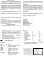
PROBES FOR BLUE LIGHT MEASUREMENT
The GOLDILUX Bilirubin Phototherapy Meter GBIL-1L has
been designed for the accurate measurement of the amount
of therapeutically effective blue light used for the treatment of
hyperbilirubinemia (or neo-natal jaundice).
The probe
detector matches the photooxidation response of Bilirubin in
the blood of jaundiced neonates. This response has been
shown to be most pronounced in a wavelength region from
400 to 500 nm with a maximum at 450 nm.
GOLDILUX
LIGHT
METERS
For effective treatment, the amount of therapeutically effective
blue light to which the infant is exposed should be in the order
of 5 - 10 µW/cm2. The quantity, in units of µW/cm2, is the
therapeutically effective power from the lamp (in µW) falling
on each square centimetre of skin of the infant. The length of
the exposure of the infant to the blue light depends on the age
and condition of the baby, its response to the exposure and
other factors as determined by the responsible physician.
The factory calibration of the probe was performed at a
distance of 800 mm from a spectroradiometrically calibrated
phototherapy lamp and at a level of approximately 40
µW/cm2. The lamp had a peak output at a wavelength of 450
nm.
In order to ensure continued accurate readings from the
probe, it should be re-calibrated by a competent calibration
laboratory at suitable intervals (yearly or as determined in
accordance with the company quality system or as specified
in applicable Government regulations).
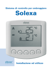
Fig. 3
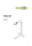
Fig. 4
USER MANUAL
GAL- 2L, GAL - 2H,
GAL- 3L with GALP probes
with special reference to: GBIL-1L
GENERAL DESCRIPTION
EXTERNAL FEATURES AND CONTROLS
OPERATING INSTRUCTIONS
MAINTENANCE AND PRECAUTIONS
CALIBRATION
SPECIFICATIONS
WARRANTY INFORMATION
2. Switch on the instrument and check its zero with the cap firmly on the
detector. Should it be necessary to adjust the meter reading to zero (e.g
for calibration purposes) adjust it via the potentiometer accessible
through the latch opening in the open battery compartment.
3. Remove the protective cap from the detector being used.
4. Take readings. Check on the units (Kilolux or lux or footcandles as
indicated by the label).
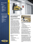
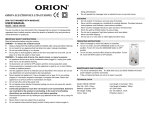
N.B.: A 9V battery is necessary for operating the instrument and this has to
be inserted in the battery compartment at the back of the meter as shown in
Fig 3.
MAINTENANCE AND PRECAUTIONS
When not in use, always put the protective cap on the detector and keep the
instrument in a safe place.
There is a warning "battery low" on the LCD display when the 9V battery
needs to be replaced.
WARRANTY INFORMATION
One (1) year limited warranty
The manufacturer warrants the light meters and probes against defects in
materials and workmanship for a period of one (1) year from the date of
original retail purchase (proof of purchase required). If an approved
distributor receives notice of such defects during the warranty period, he will
either, at its option, repair or replace products which prove to be defective
and receive a replacement from the manufacturer.
Exclusions
The above warranty shall not apply to defects resulting from improper or
inadequate maintenance by the customer, customer-supplied software or
interfacing, unauthorized modifications or misuse, operation outside the
environmental specifications for the product, improper site operation and
maintenance, an accident or abuse.
Obtaining warranty service
To obtain warranty service, the products must be returned by the purchaser
to an approved distributor. Repair or replacement of the instrument will be at
the discretion of the technician at the manufacturers. They have to be
notified of the warranty claim and the defective product returned to them.
Replacement will be at no charge if deemed to be necessary.
Shipping charges from the customer to an approved distributor shall be to
the account of the customer and shipping charges from the approved
5
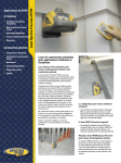
If necessary, clean the detector with a soft clean cloth or tissue moistened
with alcohol. Dry and polish lightly with a dry tissue.
1)
a)
b)
c)
d)
2)
a)
b)
CALIBRATION
Meters
Meters with a built-in detector(e.g. GAL-2L): adjust the meter reading
to zero via the potentiometer accessible through the opening in the
open battery compartment. and the cap firmly on the detector,
Expose meter to a known illuminance, emitted by a light source of the
type for which the calibration is desired. Alternatively, produce a stable
illuminance with a suitable light source of the desired type and
measure it with a calibrated light meter.
Adjust the meter with the calibration adjustment (F in Fig. 3) until it
reads correctly.
Seal the hole (F in Fig. 3) with a suitable calibration sticker.
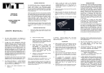
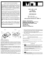
Probes
Plug the probe into the meter. Set the probe’s range selector switch (A
in Fig 4) to the lowest setting.
With the dustcap firmly in place (D in Fig 4) check the meter reading
of zero. The potentiometer P5 indicated on the rear label of the probe
2
GENERAL DESCRIPTION
The GOLDILUX series of light meters are designed to measure illuminance
of the visible spectral radiation in the units of lux or optionally in footcandles.
An external probe may be plugged into a light meter. In this case the
detector in the light meter is automatically disconnected and the displayed
reading corresponds to the quantity and the units measured with the probe.
distributor to the manufacturer shall be paid by the approved distributor.
The manufacturer shall pay for the return of the replacement product to the
approved distributor, who shall be responsible for the shipping charges to
the customer.
The liquid crystal display of the metres (GAL-2L, GAL-2H) is autoranging
over one decade. External probes (e.g. GALP-1L) have a built-in probe gain
selector switch with two different gains and thus cover a wider measuring
range than the meters with built-in detector. The probe gain settings are
multiplied as indicated on the probe labels and the switch setting indicated
by the probe range factor. Probes combined with a non-specific meter
(display - GAL-3L) offer the best combination with the widest possible
measuring range.
Warranty limitations
The manufacturer makes no other warranty, either expressed or implied,
with respect to these products. The manufacturer specifically disclaims the
implied warranties of merchantability and fitness for a particular purpose.
Some states or provinces do not allow limitations on the duration of an
implied warranty, therefore the above limitations or exclusion may not apply
to you. However, an implied warranty of merchantability or fitness is limited
to the one (1) year duration of this written warranty.
This warranty gives you specific legal rights, and you may also have other
rights which may vary from state to state, or province to province.
EXTERNAL FEATURES AND CONTROLS
Fig. 3 indicates the layout and function of the switches and connectors and
other features available on the light metres.
The ON/OFF switch (A in Fig. 3) is located on the left side of the meter
housing. To switch ON move it forward. The meter is OFF when the switch
is in the lower position.
The HOLD button (B in Fig. 3) can be used to "freeze" the display for
convenient reading by the operator. This hold button operation can be
achieved for up to 5m distance from the instrument by means of a remote
hold cable (optional extra) plugged into connector C in Fig. 3. A simple
contact closure between the two mono plug connector pins activates the
hold ("freeze") function.
The ANALOG OUTPUT of the meter is D in Fig. 3. It can be used to supply a
2V output for a full-scale reading. It has an output impedance of 10 kS and
can be used to record light levels on a chart recorder or any other suitable
data acquisition system. A stereo plug should be used to connect the
equipment to the analog output socket.
1.
OPERATING INSTRUCTIONS
Remove the instrument from its case and mount or place it in the
desired measurement position.
Exclusive remedies
The remedies provided herein are the customer's sole and exclusive
remedies. In no event shall the manufacturer be liable for any direct, indirect,
special, incidental or consequential damages, whether based on contract,
tort, or any other legal theory. Some states or provinces do not allow the
exclusion or limitations of incidental or consequential damages, thus the
above limitation or exclusion may not apply to you.
Distributor's address:
HEALTH & OCCUPATIONAL HYGIENE LAB CC
P O Box 51630
Wierde Park 0149
Tel: (012) 6533 3850 Fax: (012) 653 0958
Cel: 082 446 7532
Attn: Johann Beukes
INDIGENOUS SYSTEMS
P O Box 2662, Halfway House, 1685
Tel: (011) 315-6444 Fax: (011) 315-6432
Attn: Charles Philips, Fanie
E-Mail: [email protected]
6.
1.
d)
e)
f)
g)
has been disabled. Return instrument for repair if zero reading cannot
be obtained.
If required the reading is adjusted by turning the potentiometer P1 as
indicated on the rear label of the probe, until the reading is correct.
Set the probe range factor to the higher range factor and adjust P2 (as
marked on the rear label) until a reading of exactly 10 times lower is
achieved than with the selector switch in the lowest range factor
setting.
For probes with integral dose option(e.g. GALP-2L) - please refer to the
manufacturer. This range has been discontinued in favour of a
microprocessor range of instrumentation.
To make the adjustments on the potentiometers P1 and P2 it is
necessary to pierce the rear label of the probe. Seal again with suitable
plastic stickers after the calibration is completed.
NOTE :
*
CIE parameters
SPECIFICATIONS
Detector
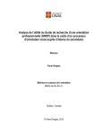
Angular
response
Spectral
response
Mass
Accessories
Re-calibration
:
Illuminance
:
:
:
:
1:200 000,
4½ digit LCD display.
9V type PP3 battery. Battery life approximately
200 hours for alkaline battery
Silicon photodiode with photo-metric filtering .
:
As indicated in Fig. 1 (nominal values).
:
:
:
As indicated in Fig. 2 (nominal values).
Display unit
:
220 g.
Protective cover for detector, instruction
manual.
Return unit to a recognized calibration
laboratory for re-calibration every 12-18 months
(depending on frequency of usage) or if calibration is in doubt for any reason.
:
3.
:
V(8) match
UV response
IR response
Cosine response
Linearity error
Error of display unit
Temperature coefficient
Fatigue
Modulated radiation
Polarization
Range change
Crest factor
Lower frequency limit
Upper frequency
limit
Calibrations should only be performed by trained metrologists in a
recognized calibration laboratory.
Measurement
parameter
Dynamic
range
Readout
Power source
**
*
**
[f1']
[u]
[r]
[f2]
[f3]
[f4]
O
["(T2=5 C)]
[f5]
f7
f8
f11
C
fl
<3%
<0.1%
<0.1%
<1.5%
<0.1%
<0.1%
O
<-0.2%/ C
<0.1%
<0.1%
<0.1%
<0.1%
>2
<40 Hz
fu
>50 kHz
International Commission on Illumination (CIE).
In accordance with CIE publication 69 (1987), "Methods of
characterizing illuminance and luminance meters".
Fig. 1
Fig 2
4.