1
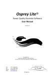
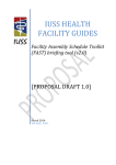
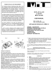
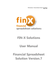
GENERAL DESCRIPTION
GOLDILUX
ULTRAVIOLET
METERS
USER MANUAL
GUVA-1L/1H, GUVB-1L/1H/GUVC-1L/1H
GUV-0L with all GUVAP, GUVBP and GUVCP probes
GENERAL DESCRIPTION
EXTERNAL FEATURES AND CONTROLS
OPERATING INSTRUCTIONS
MAINTENANCE AND PRECAUTIONS
CALIBRATION
SPECIFICATIONS
OPERATING INSTRUCTIONS
1.
2.
3.
4.
Take the instrument from its storage place and
plug in the external probe (if used), mounting or
placing it in the position where measurements are
to be made.
Switch on the instrument and check its zero with
the cap firmly on the detector (of either the meter
or the probe, depending on which is being used for
the measurement). For a meter or probe zero
adjustment, see the applicable paragraphs of the
calibration section. A zero adjustment may be
performed at any time without affecting the
calibration status of the instrument.
Remove the protective cap from the detector being
used.
Take readings. If the probe range selector switch
is at a setting other than x1, the reading must be
multiplied by the selected range factor.
MAINTENANCE AND PRECAUTIONS
Avoid touching the detector (H in Fig. 1 or D in Fig. 2)
as natural oils and acids from the skin may form a
layer, which absorbs UV, or could etch and damage the
surface. The detector can be cleaned with a soft clean
cloth or tissue moistened with alcohol. Dry and polish
lightly with a dry tissue.
4
If the UV-A and UV-B meters have to be used for the
measurement of wide-band UV sources (which emit UV
radiation over a wide range of wavelenghts, like for
instance sunlight), this should only be done after
having the meters re-calibrated for that specific type of
wide-band source. UV-C meters should not be used for
measurements on wide-band sources like sunlight at
all, quite apart from the fact that there is no UV-C
component in sunlight.
The different UV regions are internationally defined as
follows:UV-A: 315 - 400 nm, UV-B: 280 - 315 nm,
UV-C: 100 - 280 nm.
A wide range of meters and probes, covering the
various UV regions as well as different measuring
ranges and application areas are available. Ask your
authorised GOLDILUX dealer for an up-to-date product
chart if you need to select the best meter for your
requirements.
Any external UV probe (e.g. UV-B) can be plugged into
any model of UV meter (e.g. UV-A). In this case the UV
detector in the meter is automatically disconnected and
the displayed reading corresponds to the quantity
measured by the probe (units as stated on the probe).
External probes cover an even wider measuring range
than the meters with a built-in detector as they have a
built-in range selector switch (A in Fig. 2) to toggle
between two range factors. On a setting other than
unity, the reading has to be multiplied by the indicated
range factor. Probes combined with a non-specific
meter are thus an economic alternative to meters with
built-in detectors in cases where the widest possible
range is required.
1
2
3
When not in use, always put the protective cap on the
detector and keep the instrument in a safe place.
There is a warning "battery low" on the LCD display
when the 9V battery needs to be replaced.
b) With the cap firmly on the probe detector (D in Fig.
2) adjust the meter reading to zero via potentiometer
P5 as indicated on the probe's rear panel label. For
high-gain probes (probes with a range factor <.1)
this may only be possible to within ± 5 in the least
significant digit.
c) Expose the probe to a known power per unit area,
emitted by a UV source radiating in the wavelength
region to which the probe is sensitive and of the type
with which the probe is going to be used.
Alternatively, make a comparison reading with a UV
meter calibrated for the appropriate UV spectral
region.
d) Adjust the meter reading with the probe calibration
adjustment (P1 as indicated on the probe's rear
panel label), until the meter reading is correct.
e) Set the range factor selector switch to the highest
range factor and adjust P2 (as marked on the
probe's rear panel label) until the reading is exactly
10 times lower than with the range factor switch in
the lowest setting.
f) Once the rear panel label is pierced to make a
calibration adjustment, it should be sealed again with
a suitable calibration sticker.
NOTE:
Calibrations should only be performed by trained
metrologists in a recognized calibration laboratory.
Additional information on the meter for the qualified
meteorologist:
a)
Open the meter housing and adjust the voltage
between TP1 and TP2 to 7.50 ± 0.02 V via
potentiometer R2. (Note: Two of the housing
screws are covered by the rear panel label, the
other two are accessible through the open battery
compartment).
b)
Adjust the voltage between TP3 and TP4 to 1.000
± .001 mV via potentiometer R26. Close the
meter housing.
The GOLDILUX series of ultraviolet meters consists of
a number of different models of UV-A, UV-B and UV-C
meters (with built-in detector and display, Fig. 1) and a
series of external probes (with built-in detector, but
without display, Fig. 2). The external probes can either
be used in combination with any of these meters or
together with a non-specific UV meter (without built-in
detector, but with display). The non-specific UV (GUV0L) meter can only be used in conjunction with an
external probe and not by itself.
The instruments measure the power per unit area of
the UV radiation falling on the detector. The external
probes can also be ordered with a dose option
(discontinued as from 1 Jan 2000), in which case they
can also be used to measure the UV energy per unit
area falling on the detector over a certain period.
Please contact the manufacturer (MIT) for re-calibration
of these units. Such measurements of UV-energy can
now be performed far more efficiently by the “Smart
Meter” series of instruments.
The meters and probes have been specifically
designed and calibrated for use with narrow-band UV
sources (most UV lamps). In such UV sources most of
the UV radiation is emitted in a narrow wavelength
region around a dominant spectral line.
CALIBRATION
1.
a)
b)
c)
d)
2.
a)
Meters
For meters with built-in detector: With no probe
plugged in and the cap firmly on the detector,
adjust the meter reading
to zero via the
potentiometer accessible through the opening in
the open battery compartment.
Expose the meter to a known power per unit area,
emitted by a UV source radiating in the wavelength
region to which the meter is sensitive and of the
type with which the UV meter is going
to be used. Alternatively, make a comparison
reading with meter calibrated for the appropriate
spectral region.
Adjust the meter with the calibration adjustment (F
in Fig. 1) until it reads correctly.
Seal the hole (F in Fig. 1) with a suitable calibration
sticker.
Probes
Plug the probe into the meter and set the probe's
range factor selector switch (A in Fig. 2) to the
lowest range factor.
5
6
EXTERNAL FEATURES AND CONTROLS
Fig. 1 indicates the location and function of the various
switches, connectors and other features of the UV
meters, which are accessible externally. The same
features for the external UV probes are shown in Fig. 2.
The meter ON/OFF switch (A in Fig. 1) is located on
the side of the meter housing and should be moved
forward to switch on the meter.
The hold button (B in Fig. 1) can be used to "freeze"
the display for convenient reading by the operator. The
operation of this hold button can also be effected by
using a remote hold cable plugged into the remote hold
connector (C in Fig. 1).
The meters also provide an analog output (stereo
socket D in Fig. 1), which supplies a 2V output for a
full-scale reading. It has an output impedance of 10 k
and can be used to record UV levels on a chart
recorder or any other suitable data acquisition system.
SPECIFICATIONS
Measurement parameter:
Irradiance (power per unit area) or energy density
(dose).
Dynamic range: Meters: 1:200 000,
Probes: 1
: 2 000 000.
Readout
: 4½
digit
LCD
display
with
autoranging over one decade
Power source : 9V type PP3 battery. Battery life
approximately 200 hours for alkaline
battery (without using an external
probe).
Detector
: UV-enhanced silicon photodiode
with filtering for either UV-A, UV-B
or UV-C.
7
Spectral response : As indicated in Fig. 4 (nominal
values).
Accuracy
: Factory setting 5%
(UV-A),
10% (UV-B), 15% UV-C. These
figures are applicable for line
sources centred at 365 nm
(UV-A), 313 nm (UV-B) and 254
nm (UV-C). Otherwise, as
stated
on
the
calibration
certificate by a recognized
calibration laboratory.
Angular response : As indicated in Fig. 3 (nominal
values).
Dimensions
: Meters : 150 x 80 x 37 mm,
Probes : 110 x 60 x 30 mm.
Mass
: Meters : 230 g (with battery),
Probes : 120 g (with cable).
Accessories
: Protective cap for detector,
manual.
Re-calibration
: Return unit to a recognized
calibration laboratory for recalibration every 6-12 months
(depending on total dose
exposed to) or if calibration is in
doubt for any reason.
8
replacement product to the approved distributor, who shall
be responsible for the shipping charges to the customer.
Warranty limitations
The manufacturer makes no other warranty, either
expressed or implied, with respect to these products.
The manufacturer specifically disclaims the implied
warranties of merchantability and fitness for a particular
purpose. Some states or provinces do not allow
limitations on the duration of an implied warranty,
therefore the above limitations or exclusion may not
apply to you. However, an implied warranty of
merchantability or fitness is limited to the one (1) year
duration of this written warranty.
This warranty gives you specific legal rights, and you
may also have other rights which may vary from state
to state, or province to province.
Exclusive remedies
The remedies provided herein are the customer's sole
and exclusive remedies. In no event shall the
manufacturer be liable for any direct, indirect, special,
incidental or consequential damages, whether based
on contract, tort, or any other legal theory. Some states
or provinces do not allow the exclusion or limitations of
incidental or consequential damages, thus the above
limitation or exclusion may not apply to you.
12
Warranty Information
Fig. 1
Fig. 3
Fig. 2
Fig. 4
9
Approved distributor’s address
BEKA (Pty) Ltd
PO Box 120, Olifantsfontein, 1665
Tel: (011)238-0000 Fax: (011) 238-0180
Attn: Murray Cronje, Gustav Kritzinger/Adam
E-Mail: [email protected]
Http://www.beka.co.za
CEATEC
PO Box 211, Umzumbe, 4225
Tel: (039) 699-2293 Fax: (039) 699-3129
Attn: Chris Early
E-Mail: [email protected]
Http://www.ceatek.co.za
CT LABS
PO Box 897, Stellenbosch, 7599
Tel: (021) 880-9915 Fax: (021) 880-1863
Attn: Hendrik Burger
E-Mail: [email protected]
Http://www.ctlab.com
ENVIROCON INSTRUMENTATION C.C.
PO Box 2686, Northcliff, 2115, JHB
Tel: (011) 476-7323 Fax: (011) 476-5995
Attn: Howard Palmer, Dion van Riet, Brian Stowe
E-Mail: [email protected]
Http://www.envirocon.co.za
13
10
One (1) year limited warranty
The manufacturer warrants the light meters and probes
against defects in materials and workmanship for a period
of one (1) year from the date of original retail purchase
(proof of purchase required). If an approved distributor
receives notice of such defects during the warranty period,
he will either, at its option, repair or replace
products which prove to be defective and receive a
replacement from the manufacturer.
Exclusions: The above warranty shall not apply to defects
resulting from improper or inadequate maintenance by the
customer, customer-supplied software or interfacing,
unauthorized modifications or misuse, operation outside
the environmental specifications for the product, improper
site operation and maintenance, an accident or abuse.
Obtaining warranty service: To obtain warranty service,
the products must be returned by the purchaser to an
approved distributor. Repair or replacement of the
instrument will be at the discretion of the technician at the
manufacturers. They have to be notified of the warranty
claim and the defective
product returned to them.
Replacement will be at no charge if deemed to be
necessary.
Shipping charges from the customer to an approved
distributor shall be to the account of the customer and
shipping charges from the approved distributor to the
manufacturer shall be paid by the approved distributor.
The manufacturer shall pay for the return of the
11
GfG (Pty) Ltd
PO Box 2673, Randburg, 2125
Tel: (011) 955-4862 Fax: (011) 955-4741
Attn: Griselda, Casper van der Westhuizen
E-Mail: [email protected]
Http://www.gfg.co.za
MAGNITEC
PO Box 27129, Benrose, 2011
Tel: (011) 618-2720/9 Fax: (011) 614-9603
Attn: Paul Nicolai
E-Mail: [email protected]
Http://www.magnitec.co.za
GAMMATEC ENGINEERING (Pty) Ltd
PO Box 264786, Vereeniging, 1939
(016) 454-0260 Fax: (016) 423-3442
Attn: Quinton Bouwer, Nic Coetzer, Jenny
E-Mail: [email protected]
Opaque Reference Equipment
PO Box 25163, Edelweiss, 1577
3 Fulmar Rd, Daggafontein, Springs, 1559
T: (011) 363658 F: (011) 818 5870
E-mail- [email protected]
AMS HADEN
Suite 247 Pvt Bag X09, Weltevreden Park, 1714
Attn: Tony Gripping / Steve Bishop
T: (011) 475-2064
F: (011) 475-2062
E-Mail: [email protected]
H. Rohloff (Pty) Ltd
770 4th street, Wynberbg, Sandton, 2
PO Box 202, Bergvlei, 2012
Tel: (011) 786-3020 Fax: (011) 887-7199
E-mail: [email protected]
NDIGENOUS SYSTEMS
PO Box 2662, Halfway House, 1685
Tel: (011) 315-6444 Fax: (011) 315-6432
Attn: Charles Philips, Fanie
E-Mail: [email protected]
14
THE DEVENPORT RD LIGHTING COMPANY
73 Buitengracht Str, Tamboerskloof, CapeTown, 8001
Tel: (021) 424-7687 Fax: (021) 424-5211
Cell: 082 4900 350 Attn: Greg Segal
E-Mail: [email protected]
Http://www.devlight.co.za
15