1
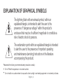
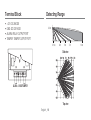
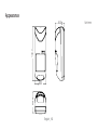
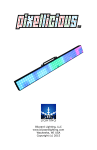
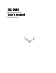
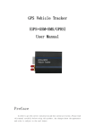
DUAL TECHNOLOGY DETECTOR User Manual SIT-1212W WARNING TO REDUCE THE RISK OF FIRE OR ELECTRIC SHOCK, DO NOT EXPOSE THIS PRODUCT TO RAIN OR MOISTURE. DO NOT INSERT ANY METALLIC OBJECT THROUGH THE VENTILATION GRILLS OR OTHER OPENINGS ON THE EQUIPMENT. Apparatus shall not be exposed to dripping or splashing and no objects filled with liquids, such as vases, shall be placed on the apparatus CAUTION These servicing instructions are for use by qualified service personnel only. To reduce the risk of electric shock do not perform any servicing other than that contained in the operating instructions unless you are qualified to do so. English _2 CAUTION CAUTION RISK OF ELECTRIC SHOCK. DO NOT OPEN CAUTION : TO REDUCE THE RISK OF ELECTRIC SHOCK. DO NOT REMOVE COVER (OR BACK). NO USER SERVICEABLE PARTS INSIDE. REFER SERVICING TO QUALIFIED SERVICE PERSONNEL. English _3 EXPLANATION OF GRAPHICAL SYMBOLS The lightning flash with arrowhead symbol, within an equilateral triangle, is intended to alert the user to the presence of “dangerous voltage” within the product’s enclosure that may be of sufficient magnitude to constitute a risk of electric shock to persons. The exclamation point within an equilateral triangle is intended to alert the user to the presence of important operating and maintenance (servicing) instructions in the literature accompanying the product. Please read the following recommended safety precautions carefully. y Do not Place this apparatus on an uneven surface. y Do not install on a surface where it is exposed to direct sunlight, near heating equipment or in extremely cold area. English _4 y y y y y y Do not place this apparatus near conductive material. Do not attempt to service this apparatus yourself. Do not place a glass of water on the product. Do not install near any magnetic sources. Do not block any ventilation openings. Do not place heavy items on the product. User’s Manual is a guidance book on how to use the products The purpose of using symbols in the manual is as follows: y Reference: To provide information for help in usage of products y Notice: If any possibility exists to cause damage to goods/persons as a result of not following the instructions Ú Please read this manual for the safety before using goods and keep it in the safe place. Note 1. Please install and use the detector following the directions. Do not touch the sensor surface as this could result in a detector malfunction. If necessary, clean the sensor surface using a soft cloth with pure alcohol. English _5 2. Avoid using products in areas with huge change of temperature. 3. The user should follow the installation and operation instructions and among other things test the product and the whole system at least once a week. For various reasons, including, but not limited to, changes in environmental conditions, electric or electronic disruptions and tampering, the product may not perform as expected. The user is advised to take all necessary precautions for his/her safety and the protection of his/her property. Product Features y y y y y y y y y y y y Adopted MCU Automatic pulse count Streamline design Doppler + Power analysis X-Band plane antenna Microwave detecting range adjustable Auto temperature compensation reducing false alarm Valve adjustable technology with high anti-interference Unique look-down design without dead angle N.C./N.O. optional for different alarm Intelligence technology differing intruder from interference signals SMT technology English _6 IR Sensor at a Glance 1. Wire exit 2. Terminal block 3. Microwave module 4. Yellow LED 5. Red LED 6. Green LED 7. LED jumper 8. RELAY jumper 9. P.COUNT jumper 10. Dual PIR 11. Microwave VR 12. Tamper English _7 Installation 1. Fix detector bracket to wall. Remove front cover of detector, take out PCB, fix back cover to bracket with screws (the best installation height is about 2.2m). 2. Set the PCB in the back cover after connecting the wires according to the TERMINAL BLOCK FIGURE full stop close the front cover. 3. Avoid installing the detector close to the following sources of interference: reflective surfaces, direct air flow from vents, fans, windows, sources of steam, oil vapor, infrared light sources and objects causing temperature changes such as heaters, refrigerators and ovens. Avoid installing the detector in the direct sunlight. 4. Ensure no object is in front of the lens of the detector, the look-down window must face down. English _8 Testing and Usage 1. With 12V power supply, the detector is set into self-checking state and the LED ON; the LED is off after 60 seconds and the detector is set into operating state. 2. Conduct walk test in detecting range, different LED ON: Green LED ON, infrared is ON; Yellow LED ON, microwave is ON; Red LED ON, infrared & Microwave is ON and the detector is in alarm status. 3. RELAY jumper is used to set alarm output mode. Select different output mode depending specification of control: 1&2/N.C. ; 2&3/N.O. . (1&2/N.C. is set as factory default.) 4. Microwave VR is used to adjust the detecting range of microwave according to customer's request. (The largest detection range is set as factory default.) 5. LED jumper is used to control LED indication without interference to detector. LED ON jumper can be interrupted after testing for concealment. 6. P.COUNT jumper is used to select the first and second pulse. Connect 1&2 to 1P (the first pulse), 2&3 to 2P(second pulse). The fisrt pulse generally used in normal circumstances, and the second pulse used in relatively harsh circumstances. (First pulse is set as factory default.) English _9 Terminal Block • • • • +12V: DC ANODE GND: DC CATHODE ALARM: RELAY OUTPUT PORT TAMPER: TAMPER OUTPUT PORT Detecting Range YUY WU\ Z \ Side view ALARM +12V GND TAMPER Top view English _10 ^ XY Specifications & Appearance Specifications Item Description Detection Range 110° x 12m Installation Height 2.2m Auto Temp. Compensation O Pet immunity – PIR Sensitivity O Selectable Pulse Count O Input Voltage DC 9V ~ 16V Current ≤30mA Power Consumption 0.36W (DC12V) English _11 Item Description Alarm Output N.C/N.O Tamper O Operating Temperature -10~+50˚C Operating Humidity 95% max Dimensions (W x H x D) 130 x 65 x 53.3mm Weight (g) 133g English _12 Appearance 130.0 53.3 53.3 65.0 English _13 Unit: mm Samsung Techwin cares for the environment at all product manufacturing stages, and is taking measures to provide customers with more environmentally friendly products. The Eco mark represents Samsung Techwin’s devotion to creating environmentally friendly products, and indicates that the product satisfies the EU RoHS Directive. Correct Disposal of This Product (Waste Electrical & Electronic Equipment) (Applicable in the European Union and other European countries with separate collection systems) This marking on the product, accessories or literature indicates that the product and its electronic accessories (e.g. charger, headset, USB cable) should not be disposed of with other household waste at the end of their working life. To prevent possible harm to the environment or human health from uncontrolled waste disposal, please separate these items from other types of waste and recycle them responsibly to promote the sustainable reuse of material resources. Household users should contact either the retailer where they purchased this product, or their local government office, for details of where and how they can take these items for environmentally safe recycling. Business users should contact their supplier and check the terms and conditions of the purchase contract. This product and its electronic accessories should not be mixed with other commercial wastes for disposal.