1
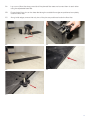
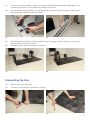
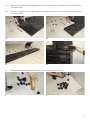
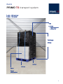
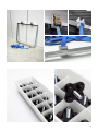
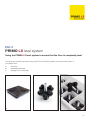
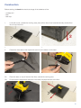
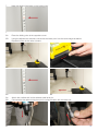
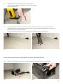
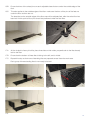
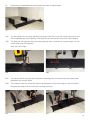
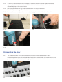
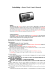
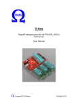
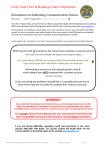
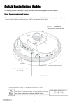
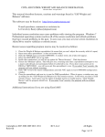
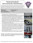
user manual
PRIMO PX flooring system
PRIMO TS transport system
PRIMO LS level system
user manual
PRIMO PX flooring system
These instructions provide the information you will need to use the Primo PX flooring system
efficiently, enabling you to lay down 430 square foot per person per hour
The instructions consist of three sections:
Part 1:
Laying and dismantling the PRIMO PX flooring system
page 3 - 7
Part 2:
PRIMO TS transport system
page 8 - 9
Part 3:
Using the PRIMO LS level system to ensure that the floor is completely level
page 10 - 19
2
Part 1
PRIMO PX flooring system
Laying and dismantling the PRIMO PX flooring system
The following elements are used in the construction of the PRIMO PX flooring system:
A.
B.
C.
floor tiles
adjustable base feet
storage boxes for base feet
A.
B.
C.
Construction
1A.
Determine the desired position of the floor.
1B.
Remove pallets with floor tiles and storage boxes from the work area. An ideal place for them is
behind you, in relation to where you plan to start laying the floor.
1A.
1B.
3
2A.
Lay a row of floor tiles along one side of the planned floor area and connect them to each other
using the adjustable base feet.
2B.
Ensure that all four pins on the base feet along the outside floor edge are positioned completely
under the floor tiles.
2C.
Along inside edges, ensure that only two of the pins are positioned under the floor tiles.
2A.
2A.
2A.
2B.
2C.
4
3A.
At the midpoint of every third tile, place three tiles standing on their sides, perpendicular to the tiles
already laid out on the floor.
3B.
Ensure that the bottom of these tiles is facing to the left, and is visible.
3C.
The first builder repeats this step, setting up multiple rows of standing tiles.
3D.
These groups of three standing tiles are ready to be constructed.
3A.
3B.
3C.
3D.
4A.
Place boxes of adjustable base feet between the rows of standing tiles.
4B.
The second builder can now proceed with the construction of the floor, connecting prepared
standing tiles to the previously laid row.
Work from left to right.
4A.
4B.
5
5A.
As much as possible, keep your feet in one position and hold several adjustable base feet in your
hand at the same time. This will reduce any delay to a minimum.
5B.
The first builder, besides setting up the standing tiles, should also ensure a steady supply of base
feet, replacing the boxes as they are emptied.
5A.
6A.
6B.
5B.
By following the steps above it will be possible to lay an average of 40m2 of floor per man hour or
430 square foot per person per hour
Repeat the above steps until the floor is fully laid.
6A.
6B.
Dismantling the floor
7A.
Remove the corner base foot.
7B.
The tile can now be easily removed from the floor.
7A.
7B.
6
8A.
Make multiple stacks of three adjacent tiles as they are removed, continuing until an entire row has
been dismantled.
8B.
Remove the stacks of tiles, placing them on the pallet. Continue in this way until the entire floor has
been dismantled.
8A.
8A.
8A.
8B.
9.
9.
Sweep together the base feet and return them to their boxes for storage.
9.
7
Part 2
PRIMO TS transport system
1 pallet = 65.3 cubic foot
1 pallet = 12.9 sq foot
Tiles:
4 x 50 tiles
= 200 tiles per pallet
= 400 sq. foot
Pallet height:
5.18 foot
3.93 foot
Boxes:
3.28 foot
9 boxes
= 234 base feet
8
9
Part 3
PRIMO LS level system
Using the PRIMO LS level system to ensure that the floor is completely level
The following materials are used in laying the Primo PX flooring system to ensure that the floor is
completely level:
A.
B.
C.
floor tiles
adjustable base feet
storage box for base feet
A.
B.
C.
10
laser set, consisting of:
D.
E.
F.
G.
H.
I.
J.
K.
L.
M.
N.
laser
tripod
pivot pin
laser eye
cordless drill
charger
folding ruler
short pivot pin
spare battery for cordless drill
spare batteries for laser
spare batteries for laser eye
PRIMO LS level system suitcase
11
Construction
Before starting do check the electrical charge of the batteries of the:
- cordless drill
- laser
- laser eye
1.
1.
2.
2.
In the left corner, outside the working area, place a floor tile on four base feet and lay another floor
tile on top of the first.
1.
Extend the three feet of the tripod and screw it to the bottom of the laser.
2.
3A.
Place the laser on top of the two floor tiles, outside the working area.
3B.
Ensure that the adjustment switches of the laser are perpendicular to the floor.
3A.
3B.
12
4.
Using the switches, adjust the laser until it is level.
4.
4.
5A.
Turn on the laser.
5B.
Position the folding ruler about 20 centimetres in front of the laser.
5A.
6.
6.
5B.
By hand, adjust the laser towards the folding laser without turning the laser itself.
6.
13
7.
Note the height of the laser on the folding ruler.
7.
8A.
8B.
Place the folding ruler at the opposite corner.
Using the adjustment switches, ensure that the laser point is at the same height as before.
Repeat this step for the other corners.
8A.
8B.
8B.
8B.
9A.
9B.
9A.
Attach the cordless drill to the stainless steel pivot pin.
Connect also the cable to the pivot pin for communication with the laser eye.
9B.
14
10.
Using the on/off button at the back, turn on the laser eye.
10.
11.
Press the turn button, starting the laser turning.
11.
12A. Turn out the screw of an adjustable base foot to extend about one centimeter.
12B. Position this base foot at a distance of about 20 centimetres in front of the laser.
12A.
13.
13.
12B.
Insert the pin of the cordless drill into the sockethead cap screw in the base foot.
13.
15
14.
Adjust the laser eye on the drill to the correct height.
You will hear a beep when the laser is at the correct height.
Fasten the laser eye.
14.
15.
Using a base foot and the drill, check to ensure that the laser beam can reach the laser eye
throughout the entire working area. When the drill is used to screw the base foot in and out, the
beep should be consistently audible.
Pay particular attention to this at the highest and lowest points of the existing floor.
15.
15.
Once this step has been completed, the floor can be laid level.
16A. Starting on one edge of the floor, lay a row of tiles and connect these using base feet.
16A.
16A.
16
16B. Ensure that two of the raised pins on each adjustable base foot are under the outside edge of the
floor.
16C. This also applies to the outside edges of the floor: make sure that two of the pins of the feet are
under the floor and two are not.
The base feet on the outside edges of the floor area will be adjusted last, after the entire floor has
been laid. At this point all four pins should be positioned under the floor tiles.
16B.
16C.
17A. At the midpoint of every third tile, place three tiles on their sides, perpendicular to the tiles already
laid on the floor.
17B. Ensure that the bottom of these tiles is facing to the left, and is visible.
17C. Repeat this step so that rows of standing tiles are prepared across the entire work area.
Each group of three standing tiles is now ready to be laid.
17A.
17B.
17C.
17
18.
Place boxes of adjustable base feet between the rows of standing tiles.
18.
19A. The first builder will now begin adjusting the height of the first row of tiles. Insert the pivot pin into
the sockethead cap screw opening in the base foot and use the drill to screw the foot upward.
19B. The laser eye will signal the drill to stop automatically when it reaches the correct height. You will
hear a beep when this happens.
Work from left to right.
19A.
19B.
20A. The second builder connects the prepositioned standing tiles to the tiles that have already been
adjusted to the correct height.
20B. This creates a new row of tiles that need to be adjusted to the correct height by the first builder.
Repeat these steps until the entire floor has been laid level.
20A.
20B.
18
21A. At all times, ensure that there are no objects or obstacles between the laser beam and the laser
eye. If contact between the laser beam and the laser eye is obstructed, the drill will not
automatically stop at the correct height.
21B. If a base foot extends too high, press the red button next to your left thumb.
The drill will ignore the signal from the laser.
21C. The base foot can be adjusted downwards by changing the rotational direction of the drill.
21A.
21B.
21C.
Dismantling the floor
22.
The laser leveled floor can be dismantled using the same method as described in part 1.
Once the adjustable base feet have been returned to their storage boxes, use the drill and the short
pivot pin to screw the feet back to their original position.
22.
19