1
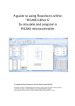
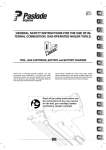
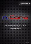
U-Axe Rapid Prototyping tool for All PICAXE® MCUs (USB Version) User Manual - Omega MCU Systems Copyright 2012 Contents Introduction ........................................................................................................... 2 U-Axe features .................................................................................................. 2 Usage ................................................................................................................... 3 1. Installing the Driver ....................................................................................... 3 2. Connecting to the Host Computer ................................................................ 3 3. Inserting the MCU ........................................................................................ 3 4. Attaching the power ...................................................................................... 4 Building Prototypes ........................................................................................... 5 Power Usage Considerations ............................................................................ 6 Alternate Connectivity ....................................................................................... 6 Using and Inserting MCU Modules .................................................................... 7 Accessing the MCU I/O ..................................................................................... 8 On board status, control and configuration ...................................................... 10 Installing a Crystal Time Base ......................................................................... 10 Specifications ...................................................................................................... 11 Supported Operating Systems ........................................................................ 11 Communications requirements ........................................................................ 11 Power Requirements ....................................................................................... 11 Supply Capability............................................................................................. 11 Physical (Main Board) ..................................................................................... 11 - Omega MCU Systems Page 1 Copyright 2012 Introduction The Omega MCU Systems U-Axe is designed to be a rapid prototyping tool for all PICAXE microcontrollers. The main board has a 40-pin ZIF (Zero Insertion Force) socket that will accept a 40-pin MCU, such as the PICAXE 40M2. However, with the available adapter modules it can be used with the entire range of PICAXE Microcontrollers from the 8-pin to the 40-pin. It was purposely designed to offer professional level handling and convenience and to provide the ability to directly attach popular and commonly available 3-wire sensors and actuators. This modular approach to prototyping allows proof-of-concept quality prototypes to be put together in a matter of hours instead of days or weeks. However, its many features which provide ease of handling, quick set-up and robust operation ensure it can easily be utilized as a programmer or in a more traditional development role as well. U-Axe features 1.6mm FR4 fibreglass board with 1oz copper and HAL tinning for long life Zero Insertion Force (ZIF) MCU socket for ease of handling and reduced wear and tear on the MCU USB 2.0 programming interface built-in for communication with the host and Programming Editor Can program all PICAXE MCUs Built-in 1 amp, regulated power supply reduces workbench clutter, improves operational reliability, reduces set-up time and provides enough power for a variety of sensors and actuators Prototyping area for customization Space for a crystal oscillator on board. Reset button for the 28 pin and 40 pin PICAXEs (and some 18-pin models). Standard 5.5mm x 2.1mm coaxial DC power socket. All signals are available through Signal-Voltage-Ground (SVG) headers for use with commonly available sensor/actuator ‘bricks’. Wire jumpers with DuPont style connectors can be used for attachment to other circuits or a solderless bread-board - Omega MCU Systems Page 2 Copyright 2012 Usage 1. Installing the Driver The U-Axe uses a Silicon Labs CP2103 USB bridge for communication and downloading programs from the PICAXE Program Editor. This requires that a driver be installed before the U-Axe is attached to the host computer and powered up. The latest driver can be downloaded either from the Downloads page at www.omegamcu.com or from Silicon Labs website at www.silabs.com. Download the driver setup program to your computer and run it. We strongly suggest you use the default options, and follow the prompts. Before clicking “Finish” during the install procedure, make sure the ”Launch the CP210X VCP Driver Installer” check box is checked. Then follow the prompts to install the VCP driver. 2. Connecting to the Host Computer The U-Axe is equipped with a standard USB “B” connector and can connect to a host computer using a standard USB “A to B” cable as shown (not included). The U-Axe SB will not be discovered by the computer until the power is applied as in step 4 or configured to be powered from the USB port. OMS recommends you use as short a USB cable as you can. 3. Inserting the MCU In order to reduce wear and tear on your microcontroller chips and increase usability and accessibility, the U-Axe is equipped with a zero insertion force (ZIF) socket. To place an MCU into the socket make sure the lever is in the vertical position then place the chip into the socket as shown with its pin 1 adjacent to the lever. Steady the board and lower the ZIF socket lever to just past horizontal into the locked position. This will clamp the microcontroller into place. Removal of the chip is achieved by returning the lever to the vertical position. - Omega MCU Systems Page 3 Copyright 2012 4. Attaching the power The U-Axe is powered from an external source. The on-board regulator and standard DC power jack allow for a variety of power options. Any filtered DC source of between 7.5V and 23V can be used. Make sure the chosen power supply delivers positive voltage through the center conductor and negative through the outer sleeve as shown here. The most convenient and popular external power sources are a 9V AC-DC switching type (switchmode) adapter, a 6-cell ‘AA’ battery pack, or a 9V battery. The 9v battery, if used, should only be used for MCU programming as it does not have the current capability to power shields or modules. The 9V AC-DC switching type (switchmode) adapters are preferred over the transformer type adapters and batteries as they provide a more stable supply, are lighter, take up less space and are generally enormously less expensive to use. With the USB cable connecting the U-Axe to the host, and the MCU inserted, apply the power by connecting the chosen power source. At this point Windows will detect the USB bridge, install the virtual com port driver and assign a com port number. Use Device Manager to determine which com port was assigned. This will be needed to properly configure the PICAXE Programming Editor. At this point you are ready to begin downloading programs to your PICAXE. - Omega MCU Systems Page 4 Copyright 2012 Building Prototypes The main design feature of the U-Axe is it ability to directly attach sensor and actuator modules without any additional circuitry or connectivity boards. These modules, commonly know as ‘bricks’ use a 3wire connection to the host controller. The three wires carry Signal, supply Voltage and Ground, and terminate in a standard 3-pin header connector. These can be directly attached to the headers on the U-Axe where each signal from the MCU is brought out and mated with a 5v and ground pair. Signal is the pin closest to the MCU socket and the pin labels, supply voltage is in the middle and ground is on the outside. Generally speaking, the connectors are not keyed and there is no discernable standard to the coloring of the wires. However, White – Signal, Red – Voltage, Black – Ground is a common. As well, placing Voltage between Signal and Ground virtually assures that damage to a module is unlikely. That not withstanding, it is advisable to consult the documentation supplied with the brick to ensure connections are made properly so that they function properly from the start. Using this modular approach, proof of concept prototypes can be assembled in mere minutes and the process of writing the code can begin just as quickly. The resulting prototypes are portable, repeatable and robust and not susceptible to damage like a solderless breadboard circuit. - Omega MCU Systems Page 5 Copyright 2012 Power Usage Considerations With a Vin of 9V, the U-Axe power supply is capable of supplying up to 450mA in free air* and up to 1 Amp with adequate additional heat sinking. 1 Amp of current should easily be enough to meet needs of any number of sensors, as these generally have small power requirements. Actuators and some shields, on the other hand, such as motors, servos, buzzers, etc., generally have much higher power needs. Some planning and common sense are required in this respect. Small servos, motors and relays are generally okay if proper noise suppression is a part of their design. However, it is advisable to know and take heed of the specifications and the nature of the loads presented by actuators and shields. In particular, larger motors, servos, relays, solenoids and other inductive loads can have very large peak current demands and are not suited to direct attachment to the U-Axe. In these cases, it is recommended that isolated driver boards or relays be utilized and that a separate power source be provided for the heavy loads. Generally, the more you add on, the more power you will be consuming and it is a good idea to keep track of power consumption *(CAUTION: The regulator can get very warm under these conditions) Alternate Connectivity The system of SVG headers used on the U-Axe makes it very versatile in connecting to any environments to be sensed and controlled. Almost any imaginable scenario can be accommodated. Should there be a need to interface a custom or non-modular circuit, you may need to attach the U-Axe to another device or a breadboard. This can easily be accomplished using ‘Dupont’ style female to male or female to female jumpers like those shown in the picture above. In fact, as shown, you can build prototypes with modules and breadboard circuits at the same time or in any combination you choose. Just make sure that the power needs are tracked so that you do not run into problems due to overloading. - Omega MCU Systems Page 6 Copyright 2012 Remember, if you are using a breadboard circuit as a part of your prototype project keep in mind that the ground of the U-Axe will need to be properly connected to the off-board circuit’s ground to ensure a good voltage reference and a suitable return path for power and signals. Failure to provide this may result in some very strange and difficult to diagnose behavior of the combined circuit. Using and Inserting MCU Modules To utilize the U-Axe with other PIXAXE MCUs, a set of 3 modules is available. Each module consists of an appropriately sized ZIF socket mounted to a circuit board that maps the hosted MUC’s pins to the U-Axe pin-out. See the section below (Accessing the MCU I/O) for mapping information. 1. The UCM820 module can host 8, 14 and 20 pin PICAXE microcontrollers. 2. The UXM18 module hosts 18-pin microcontrollers 3. The UMX28 module hosts 28-pin microcontrollers To insert the modules, begin by making sure the U-Axe’s ZIF socket is fully open and it’s lever is in the vertical position. If you insert a module with the ZIF socket in the locked position you may damage it. Next, gently place the rear pins of the module into the U-Axe socket then gently press the front pins into place. Once the module is fully inserted and level with the U-Axe socket, lock it into place with the main lever as shown below. Remember, the lever is locked when it has been lowered just past the horizontal. Be careful doing this the first few times. It is important that the operation goes smoothly so as not to damage the U-Axe’s ZIF socket. You should never need to use more than a light pressure in inserting the module. If the module does not insert easily, it may be hung up on the contacts of the U-Axe’s ZIF socket. If this happens, remove the module and start over. - Omega MCU Systems Page 7 Copyright 2012 Accessing the MCU I/O When inserted into a U-Axe via the UXM820 module, the I/O pins of the 8-pin and 14-pin MCUs map to the U-Axe in the following fashion: 8-pin MCUs to U-Axe (UXM820 module) 8-pin MCU 1 – +V 2 – Serial In (C.5) 3 – C.4 4 – C.3 5 – C.2 6 – C.1 7 – Serial Out (C.0) 8 – 0V U-Axe Vcc Serial In (not accessible) C.7 C.6 B.1 B.0 A.4 GND 14-pin MCUs to U-Axe (UXM820 module) 14-pin MCU 1 – +V 2 – Serial In (C.5) 3 – C.4 4 – C.3 5 – C.2 6 – C.1 7 – C.0 8 – B.5 9 – B.4 10 – B.3 11 – B.2 12 – B.1 13 – Serial Out (B.0) 14 – 0V U-Axe Vcc Serial In (not accessible) C.7 C.6 C.5 C.4 C.3 B.4 B.3 B.2 B.1 B.0 A.4 GND Except as indicated below, all pins and ports on 18, 20, 28 and 40 pin MCUs map directly and as designated such that Pp.Np maps to Pu.Nu, (where Pp and Np are the port and port pin number on the PICAXE and Pu and Nu are the port header and pin number on the U-Axe). As an example, the pin on the PICAXE associated with A.1 will map to the SVG header location A.1 on the U-Axe - Omega MCU Systems Page 8 Copyright 2012 18-pin MCUs (UXM18 module) 18M and 18X – Inputs map to port C and outputs map to port B. Reset maps to reset button and to C.5 18M2 – C.5 maps to reset button and to C.5. The reset button can be used as an input to C.5. C.4 (Serial in) maps to Serial in and C.4. The data from the host appears on C.4 so that signal in not available while the 18M2 is in the U-Axe. Physical pin 4 of 18-pin MCUs is tied to VCC through the 4K7 resistor in the reset circuit. 20-pin MCUs (UXM820 module) 20M – Inputs map to port C and outputs map to port B 20M2 – Serial Out (DAC) maps to A.4 20X2 – A.0 / Serial out / (Out) maps to A.4 28-pin MCUs (UMX28 module) 28X1 ADC 0 / In a0 – ADC 3 / In a3 map to A.0 – A.3 In 0 / Out c0 – In 7 / Out c7 map to C.0 – C.7 Output 0 – Output 7 map to B.0 – B.7 40-pin MCUs (No module) 40X1 ADC 0 / In a0 – ADC 3 / In a3 map to A.0 – A.3 ADC 5 – ADC 7 map to A.5 – A.7 In c0 / Out c0 – In c7 / Out c7 map to C.0 – C.7 Output 0 – Output 7 map to B.0 – B.7 Input 0 – Input 7 map to D.0 – D.7 - Omega MCU Systems Page 9 Copyright 2012 On board status, control and configuration The green power LED indicates that power is applied when lit. Data communication through the MCU’s serial port is monitored with the red RX LED and the blue TX LED. These will be active any time those signals are, such as when code is being downloaded from the Programming Editor or when the MCU’s serial port is being used for other communication. PICAXE 40-pin, 28-pin an older 18-pin (not the 18M2) MCUs support a wired reset signal. Pressing the reset button located at the upper right-hand side of the U-Axe will initiate a hard reset of those MCUs. On PICAXE 18M2 chips, the reset button can be used as an input to C.5. Installing a Crystal Time Base While all PICAXE microcontrollers have an internal oscillator as a time base an clock, the 40-pin and 28-pin models will also accept an external crystal time base. The internal oscillator is considerably less accurate than a crystal, and while fine for the vast majority of requirements, some users or applications may demand more precision. In order to accommodate this possibility the U-Axe has a pre-wired crystal circuit. Just insert the crystal and the appropriate load capacitors (usually around 22pf) in the provided areas as shown, and solder into place. See the PICAXE documentation for more information on external clocking and how to set the frequency. It should be noted that while PICAXE mention a ceramic resonator, a crystal is considerably more accurate. Note: The U-Axe has been designed to work with the PICAXE® Programming Editor, which is available at www.picaxe.com/Software. PICAXE® is a registered trademark of Revolution Education Ltd. - Omega MCU Systems Page 10 Copyright 2012 Specifications Supported Operating Systems The CP2103 USB bridge driver supports the following operating systems: Windows XP Windows 2003 Windows Vista Windows 7 Communications requirements Interface Type: USB 2.0 Connection: Standard USB “B” Power Requirements Supply Voltage: Supply Current: 7.5V – 23V DC @ 1 amp Typically between 38mA and 42mA with the MCU Only (no modules attached). Supply Connector: 5.5mm x 2.1mm center positive co-axial jack NOTE: Supply voltage should never exceed 24V dc. Observe polarity – this board requires a center positive supply. Check polarity before attaching the power source. Supply Capability Main Board Voltage: Max current: Free-air current: 5V (4.8V – 5.2V) 1A (with adequate additional heat sink) ~ 450mA @ VIN = 9V, 25 oC (no added heat sink) Physical (Main Board) Length: Width: Height: Mounting: Weight: Operating Temp. 110mm 69mm 17mm 58.5mm x 84mm 60g 0oC – 85oC Note: PICAXE® is a registered trademark of Revolution Education Ltd. OMS PO Box 74 Bracebridge, ON, P1L 1T5 Canada - Omega MCU Systems Page 11 Copyright 2012