1
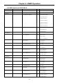
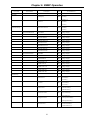
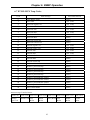
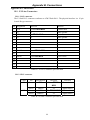
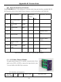
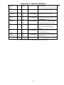
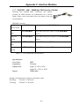
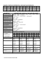
Appendix C. Interface Modules
C-5. RS-530 to RS-449 Adapter Cable
When the ETU02-MUX is ordered with an RS-449
interface, the physical interface is a 37-pin male D-type
connector wired in accordance with Table C-5.
RS-530 to RS-449 adapter cable
SIGNAL RS-530 RS-449 RS-449
FUNCTION PIN
PIN
CIRCUIT
Protective
1
1
Frame
Ground
Signal
7
19,20, SG,RC,
Ground
37 SC
Transmitted
2
4
SD(A)
Data
14
22 SD(B)
Received
3
6
RD(A)
Data
16
24 RD(B)
Request to
4
7
RS(A)
Sent
19
25 RS(B)
Clear to
5
9
CS(A)
Sent
13
27 CS(B)
Data Set
6
11 DM(A)
Ready
22
29 DM(B)
Data
20
12 TR(A)
Terminal
23
30 TR(B)
Ready
Data Carrier
8
13 RR(A)
Detect
10
31 RR(B)
External
24
17 TT(A)
Transmit
11
35 TT(B)
clock
Transmit
15
5
ST(A)
Clock
12
23 ST(B)
Receive
17
8
RT(A)
Clock
9
26 RT(B)
Remote
21
14 RL
Loop back
Local
18
10 LL
Loop back
Test Indicator 25
18 TM
DESCRIPTION
Chassis ground.
May be isolated from signal ground.
Common signal ground.
Serial digital data from DTE.
Serial digital data at the output of the ETU02MUX receiver.
A ON signal to the ETU02-MUX when data
transmission is desired.
Constantly ON.
Constantly ON,
Except during test loops.
DTR not used, used for a received serial data rate
clock input from the DTE.
Constantly ON, except when a loss of the received
carrier signal is detected.
A transmitted data rate clock input from the data
source.
A transmitted data rate clock for use by an
external data source.
A received data rate clock for use by an external
data source.
When on, commands ETU02-MUX into remote
loop back.
When on, commands ETU02-MUX into local loop
back.
ON during any test mode
Table C-5 RS-530 to RS-449 pin allocation
105