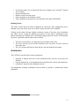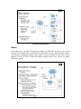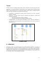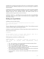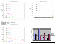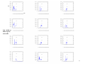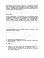
1
Initial studies of networking simulation on COTSon
Diego Lugones, Emilio Luque, Daniel Franco, Juan C. Moure, Dolores Rexachs, Paolo
Faraboschi, Daniel Ortega, Galo Giménez, Ayose Falcón
HP Laboratories
HPL- 2009-24
Keyword(s):
Networking, simulation, COTSon, full-system
Abstract:
HP Lab’s COTSon is a full system simulation framework based on AMD’s SimNow. COTSon
allows for simulating complete computing systems, ranging from a single node to a large cluster
of hundreds of multicore nodes.
This technical report is the result of the first six months of the collaboration project between HP
Labs and the Universitat Autònoma de Barcelona. The goal of this collaboration is to analyze
network simulation in the COTSon environment, in order to propose and implement network
topologies. The ultimate goal is to be able to perform reliable and accurate networking
simulations using COTSon.
This report explains how to configure COTSon to perform a network simulation, and describes
the different steps to run a parallel application (NAMD, a molecular dynamics benchmark using
MPI) and obtain performance results. The different analysis and results shown in this paper were
carried out in 2007, with the versions of COTSon and SimNow available at that moment. Some
of the configurations and steps described in this document may have changed since then.
External Posting Date: February 6, 2009 [Fulltext]
Internal Posting Date: February 6, 2009 [Fulltext]
© Copyright 2009 Hewlett-Packard Development Company, L.P.
Approved for External Publication
Initial studies of networking simulation on COTSon
Diego Lugones*, Emilio Luque*, Daniel Franco*, Juan C. Moure*, Dolores
Rexachs*, Paolo Faraboschi§, Daniel Ortega§, Galo Giménez‡, Ayose Falcón§
[email protected]
*
Dept. of Computer Architecture and
Operating Systems (CAOS)
Universitat Autònoma de Barcelona
§
Exascale Computing
Lab
HP Labs
‡
Enterprise
Solutions Programs
HP
Abstract
HP Lab’s COTSon is a full system simulation framework based on AMD’s SimNow.
COTSon allows for simulating complete computing systems, ranging from a single node to
a large cluster of hundreds of multicore nodes.
This technical report is the result of the first six months of the collaboration project
between HP Labs and the Universitat Autònoma de Barcelona. The goal of this
collaboration is to analyze network simulation in the COTSon environment, in order to
propose and implement network topologies. The ultimate goal is to be able to perform
reliable and accurate networking simulations using COTSon.
This report explains how to configure COTSon to perform a network simulation, and
describes the different steps to run a parallel application (NAMD, a molecular dynamics
benchmark using MPI) and obtain performance results. The different analysis and results
shown in this paper were carried out in 2007, with the versions of COTSon and SimNow
available at that moment. Some of the configurations and steps described in this document
may have changed since then.
1
1 Introduction
This document exposes the six month’s work accomplished on the COTSon project, in the
HP Labs-UAB collaboration context. COTSon project’s goal is to build a simulation
infrastructure that allows its users to faithfully simulate multi-node systems, and also the
software to accomplish such goal. It is being developed mainly by the Barcelona branch of
the Advanced Architecture Lab together with external partners from AMD.
System simulation can be thought of as composed of two different interrelated processes,
functional simulation (also known as emulation) and timing simulation. Functional
simulation is necessary to verify correctness. It emulates the behavior of a real machine
running a particular OS and models common devices like disks, video, or network
interfaces. Timing simulation is used to assess the performance. It models the operation
latency of devices emulated by the functional simulator and assures that events generated
by these devices are simulated in a correct time ordering. In order to achieve this goal, is
necessary to be able of doing both functional and timing simulation in an affordable amount
of time, i.e. as fast as possible. COTSon combines the fastest known techniques in both
areas, functional and timing simulation, with the outcomes of our research in sampling,
network timing and others.
Not only fast simulation is important. Accuracy/Speed trade-off must be handled. Since it is
impossible to achieve both fast and totally accurate, COTSon research is focused on best
combination of both, trading speed for accuracy whenever this is important or the opposite.
Functional simulation is a mature field. Virtual machines are able of functionally
simulating a complete one node system with negligible slowdowns. COTSon uses
SimNow, a VM by AMD, to do its functional simulation. SimNow provides COTSon with
a steady trace of events and accepts feedback regarding the time consumed by the system.
This way, SimNow is in charge of functionally emulating the system and COTSon provides
it with a measure of how time should be proceeding.
COTSon not only controls one instance of SimNow, but many. One of the features of
COTSon is the ability to couple together several instances of SimNow plus timing and
make them work together to simulate a complete multi-node system.
COTSon parts
COTSon consists on several parts of which the most important are: SimNow, AbAeterno,
Mediator and, Control coupled with several scripts and smaller applications that glue
everything together.
2
COTSon Architecture
SimNow [6] is an application that runs on AMD64 machines which is in charge of
faithfully functionally simulating a complete system. AbAeterno is a dynamically load
library (DLL or shared object) which when loaded by SimNow becomes responsible for
determining the exact time the simulation is taking. This is what we call timing simulator.
AbAeterno dynamically instructs SimNow of certain events which it is interested in, such
as instructions executed, disk accesses, network accesses and such, and feeds back to
SimNow the absolute time of simulation. To do this it relays on timing modules, which take
the events and produce a time measurement.
The mediator is an application which complements SimNow's access to the network.
Several SimNow instances are originally distributed with a mediator which serves all the
purposes that it needs as a standalone application. At HP several versions of mediators have
been developed. These versions surpass AMDs ones and which better integration with
COTSon. Every SimNow instance can be pointed to a running mediator (potentially
running in another host machine) which will be the endpoint of all network packets sent out
by the simulated guest. The mediator will be responsible for allowing more than one
COTSon node (i.e., an instance of SimNow plus AbAeterno) to communicate among them
and potentially with the rest of the internet. The latter is achieved with external tools such
as Slirp and VDE.
The Control interface, COTSon Control or simply Control, is responsible for coordinating
the several COTSon nodes, which may be running in different machines and work together
towards a joint simulation.
3
COTSon Control Interface
The control is programmatically composed of a web framework application which lets the
user control the different clusters of simulations and also of some scripts which allow
running cluster simulations in batch mode. Currently the control is under heavy
reconstruction so changes should be expected; it is more amenable for users and simpler to
set up.
2 Tasks
Within the COTSon project, we are interested on multiple SimNow’s interconnection and
reliable cluster simulation issues. Cluster’s networks are implemented via Mediator.
Mediator provides Ethernet connectivity among simulators and works with simulations
distributed across multiples hosts. Mediator also manages the timing modules for a
networked cluster and is responsible for network modeling (topologies, switches, cards,
etc.), queuing up pending network packets and computing the delays due to network
congestion.
Our first milestone involves the following objectives.
4
1) Getting background on COTSon project, with special interest on the system
interconnection, network modeling and simulation techniques, COTSon Control
interface, timing models, synchronization and multiple parallel simulators coordination.
2) Analyzing the software application set that performs networking functionality, such as
Mediator and related scripts and daemons, Control Webapp (Java, Tomcat, Jsp and
SQL Database) and external software (VDE, Slirp, XML-RPC).
3) Debugging and compiling the whole system.
4) Setting system simulation parameters and features such as lock-step quanta (Q), extra
flags, cluster elements (*.BSD, *.hdd …)1, services (start, stop, suspend and resume;
simulation and host commands) and metrics (timing charts).
5) Creating a computer’s architecture with SimNow’s BSDs, installing software
applications and developing a cluster using several SimNow’s instances.
6) Selecting a representative user application in order to evaluate cluster simulation when
system parameters are modified to get different speed/accuracy tradeoffs.
7) Analyzing several metrics and gathering traces in order to compare functional and
timing simulations.
3 Document organization
The rest of the document is organized as follows: Section 3 presents a discussion of
network timing simulation and how it is implemented. In Section 4, COTSon Control
environment and architecture is fully described. In Section 5, a quantitative description
about mediator components is accomplished. Section 6 analyses the experimentation results
performed on a cluster for NAMD application. Finally, conclusions and future work are
drawn.
4
Network Timing Simulation
This section discusses network timing simulation and its current implementation in the
COTSon Control and Q Mediator. Before getting into detailed description it is important to
understand some of the networking.
Background
In a network high-level view, packet reception causes the network interface device to raise
an interrupt; in response to this, the interrupt handler copies the packet from the device to
1
A BSD file contains the configuration and architecture of the computer system.
A HDD file contains the configuration of the attached disk.
5
main memory and then processes it [2] (looks at headers etc.). Packet handling itself should
(and is) not done in the interrupt context (i.e., when some interrupts may be masked), but
done upon return from the interrupt context (i.e., when all interrupts are enabled). Nothing
can be done to simulate latency on packet reception: bandwidth and latency simulation
need to be simulated at packet transmission.
Packet transmission seems to be much simpler than reception. DMA during transmission
works as a "streaming" mapping instead of a "consistent" mapping. The transmission
routine simply sets up the DMA mapping and some registers on the hardware and then
exits. It does not wait for the device to physically complete transmission. Concurrent
accesses to the driver's transmission function (hard_start_xmit) are prevented by a spin
lock (xmit_lock).
The device can only handle a limited number of outstanding packets. Thus, calls to the
transmission function are throttled — when the transmission ring is full, no more calls to
the driver's transmission function are made and the packets’ queue is stalled. When the
device is ready for more, then the queue is woken up and packets in the queue can be sent.
The device driver provides a function which instructs the hardware to begin the
transmission. Therefore transmission happens in parallel with CPU processing, and
bandwidth can be simulated by blocking the device for as long as needed. In the other hand,
latency can only be simulated by stalling the main CPU simulation for the time the real
network will waste moving a bit from one node to the next.
NIC, device, kernel and user level
6
Advanced NIC Topics
•
NAPI [2]. It is a modification on the device driver packet processing framework,
which is designed to improve the performance of high-speed networking. NAPI
works through:
o
Interrupt mitigation. High-speed networking can create thousands of
interrupts per second; all of them tell the system something it already knew:
there are a lot of packets to process. In this sense NAPI allows drivers to run
with (some) interrupts disabled during times of high traffic, with a
corresponding decrease in system load.
o
Packet throttling. When the system is overwhelmed and must drop packets,
it's better if those packets are disposed of before much effort goes into
processing them. NAPI-compliant drivers can often cause packets to be
dropped in the network adapter itself, before the kernel sees them at all.
•
Adaptive Interrupt Coalescence. Some high speed NIC and drivers, especially those
with TSO (TCP segmentation Offloading) interrupt less frequently the OS to let it
work in something, by grouping several packets in a single interrupt.
•
Integrated Network Interfaces for High-Bandwidth TCP/IP [1]. Provides the
integration of a very simple NIC into the CPU to avoid DMA, thus reducing latency
of current designs.
Quantum Based Networking Simulation
COTSon implements a Quantum based simulation, with quanta (Q) larger than travel
latency between two nodes [5]. Some problems need to be taken into account and will be
described here. In addition to synchronization, there is the need of simulating networks
properly, basically its latency and bandwidth.
Latency and Bandwidth Simulation
Real network bandwidth and latency will be typically worse that the network we try to
simulate, usually a very low latency high bandwidth cluster LAN. Moreover network
functional simulation adds additional latency to every packet submitted, because packets
are sent twice (node to mediator and mediator to node) and the mediator will take some
time processing the packet.
In COTSon, network latency and bandwidth simulation happens in the source NIC device,
but network timing information is gathered in the mediator, which represents the virtual
network.
To do this several mechanisms are needed:
7
•
A mechanism to model the network timing. The best place to model the network is
the mediator, the Q Mediator includes timing modules that detect when congestion
happens, or when internal switch buffers are full. This is accomplished based on
packets’ information that traverse mediator.
•
A mechanism to propagate current network timing parameters to SimNow
simulation, basically the latency a packet will suffer due congestion in the switch or
due the network if it is full of traveling packets (throughput). These timing modules
work based on quantum. Every time a quantum starts, the timing module is notified
and the quantum length is well known. When a node ends a quantum, the control
notifies the mediator to let the control know the network timing information that
was calculated during the past quantum
•
A mechanism to simulate the delay suffered when a packet is sent to the NIC from
the machine (i.e., the NIC is busy injecting other packets into the network).
SimNow offers an interface to synchronize devices. When a NIC is accessed to send
a packet, the AbAeterno timing modules will communicate to SimNow that this
device will have a delay.
Internally the action of sending a message won't take place until the initial time plus delay
is reached. At the same time the device won't remove the packet from the ring buffer until
[initial time+delay], when it really will send the packet. When the ring buffer is full the
driver won't let the OS queue more packets. The e1000 device implementation seems to
work quite like this, when delays are very long e1000 buffers are filled quickly, this means
that the e1000 device is not communicating the driver that the number of outstanding
packets has been reached. The AbAeterno timing will add a delay that is a function of the
bandwidth, the packet size, and some NIC setup delay; this will simulate the bandwidth of
the network.
•
A mechanism to simulate latency. Latency affects the node which sends a packet
and is defined as the time a bit needs to fly from source node to destination. Latency
and is invisible to a node receiving a packet. If the simulator is “frozen” enough
time when a packet is submitted, it will be like time is not passing for source node
and latency will be really short [5].
Q Mediator
The mediator includes a simple network timing module, but more elaborate methods can be
built on top. The timing model in the mediator gets notified every time a new packet
crosses the network. Also the timing model gets notified when a cluster simulation
quantum starts or ends. With this information, the model calculates the latencies for each
pair of nodes. This latency is then given to SimNow and the NIC of the virtual machine
applies the calculated latency to the outgoing message.
8
There are two timing model interfaces; the simplest one considers the latency between two
nodes to be the same for all pairs. A more elaborate implementation allows a 2D matrix of
latencies one for each nodes’ pair combination.
Network timing is activated when the “-mdeconf” parameter is provided; this parameter
includes a path to a file where the network model is configured. By default the Q Mediator
uses the SimpleSwitch model. This model allows a constant bandwidth for any packet up to
a maximum bandwidth. When the maximum bandwidth is reached the latency is 8 times the
normal one. It is mean to represent an 8 port crossbar. The following is a typical
configuration for this model, in the “switch.conf” file:
max_bandwith = 10 //Mbits
latency = 10
//micro secs.
5 COTSon-Control
The COTSon-Control application can be used to launch and monitor simulations of clusters
of machines [4] that happen in several simulated machines. The objectives of the control
are:
•
•
•
•
To provide a GUI environment to SimNow simulations
To provide a monitoring and management system when simulating cluster of
machines
To synchronize simulations that happen across several nodes
To distribute timing information from the Q Mediator to each of the SimNow and to
provide feedback forms each SimNow to the Q Mediator.
Terminology
The host machine/system is the machine/system in which SimNow is being hosted. The
simulated machine/system is the AMD processor-based machine/system that is being
simulated.
A BSD [6] contains the configuration of a computer system (how models are connected
together and their settings), sometimes called a virtual motherboard description and a
checkpoint of the state of all devices in the simulator. Thus the BSD file may include
information such as the number of processors in the simulated system, properties of
DIMMs, image filename(s) of hard drive(s), etc.
Environment
The control main page has three sections:
9
•
•
•
Simulated Machines – These are the SimNow BSDs (virtual machines), with a
particular hard disk configuration and a run script. Typically any standard run script
may be used, but customized scripts might be created.
Hosts – Those are physical simulation nodes that can be used in a given simulation.
Clusters – A cluster is a particular configuration, which can have one or more
nodes. For each node we need to setup the BSD that will be used and the Host on
which the machine will run.
There are two additional "links" on the main page, which are for advanced users:
• Bean Shell – this is a shell interface to create scripts inside the control itself
• Timers – this is a page to create timer charts that are shown when clusters are
running
Cluster Form
The cluster form lets edit and monitor the clusters status.
Control interface
•
•
State: shows the state of the cluster: STOP, RUNNING
Start, Kill, Clean, Logs: You can do any of those actions with the whole cluster.
o Start - will start all nodes in the cluster - this operation can take some time
depending on the number of nodes.
o Clean - this will stop all nodes and cleanup any log files created by the
simulation (basically the sandbox)
10
o
o
o
o
•
•
•
Kill - this will stop all nodes but will leave the log files and scripts inside the
sandbox
Hibernate - this will stop all nodes after saving the estate of them
Resume - if a cluster was hibernated, and it is not running you can resume it,
will restart all nodes in the previous estate.
Logs - this will show you all log files create by all nodes.
Timer Chart Wnd - This is to define the number of data points to show in the charts;
200 will show the last 200 data points.
Quantum/Synchronize nodes: When nodes are synchronized, this defines the
number of µsecs of the quantum
Extra Flags: Additional parameters that can be passed.
Extra flags
The following will start the timing modules in SimNow using the configuration file
dynamic.conf and will enable the timing modules in the mediator with the configuration in
switch.conf
-aarg'-i /mnt/COTSon/data/dynamic.conf' -medconf /mnt/COTSon/data/switch.conf.
The following will do the same as before but will indicate the mediator binary to use, and
the timing library that we want.
-medconf /home/user/SimNow/timing/switch.conf
-m /home/user/mediator
/home/user/AbAeterno.so -aarg '-i /home/user/aa.conf'
-aalib
The following will start the mediator with a tun-tap interface
-tap tap0
The following tells the mediator to run using Slirp (NAT), use a particular RPC control port
and use 2 threads in the mediator scheduler.
-slirp - rpcport 8011 -nt 2
Next if the full list of extra flags that you can use:
•
Basic Options:
11
-v
-m med
increase verbosity
path to mediator script
[/home/user/COTSon/trunk/control/mediator/vdemed.pl]
-mt
threads number of mediator data threads [8]
-medrpc port port used by the mediator RPC server [8081]
-medmaxmsg
maximum number of messages the mediator can queue
[1000000]
-medconf
mediator timing configuration file
-s sleep
delay between node start [1]
-root dir
SimNow local root directory [/opt/SimNow]
-aa
use AbAeterno std library
[/home/user/svn/trunk/AbAeterno/AbAeterno.so]
-aalib lib
specify AbAeterno shared library
-cmdlib lib
specify console command shared library
[/home/user/svn/trunk/control/src/cmd_interface/cmd.so]
•
Node Options (if a single item is passed, it's assumed common to all nodes):
-aarg 'args' comma-separated list of AbAeterno parameters []
•
Networking Options:
-slirp
-net nw
-tap TAP
-dpipe host:sock
-med
host:port
-tmp
dir
run Slirp on the VDE switch [false]
Slirp network [192.168.10.0]
connect to tap TAP interface TAP (requires sudo priv.)
[false]
connect to remote VDE (ex. -dpipe
srv2:/tmp/clust2/vdesock)
don't start mediator, connect to remote (ex. -med
srv2:2345)
temp directory [/tmp]
Nodes
The nodes section shows the list of nodes that are part of the simulation. To add a node just
adds the simulated machine (BSD) and the host where you want it to run.
For each node it is possible to see its state, its ID, the host where it runs, and its VNC
display. The state of each node can be:
•
•
•
STOP, meaning the cluster is stop, or if the cluster is running, means that the
process ID associated to SimNow is not found
STARTING, the node is running but the OS is not fully booted.
RUNNING, the node is running and the OS is fully booted (and the OS has the
Xtools installed)
From the node list, it is possible to:
12
•
•
•
•
•
See the Host name, if in red means the host isn't working or the “scotsond”2 daemon
is not running
Stop a particular node,
Remove a node from the cluster
Send commands to the SimNow console
Send commands to the guest OS, only possible if the node is RUNNING
Defining Charts
The charts section shows the charts configured for each node. The configuration can be
changed at any time and as soon as new data is ready, the chart will be updated.
Clicking on the chart will open a higher resolution version of the same chart. In addition
new charts can be created by defining new metrics on the metrics management form.
Metrics and charts are defined with a small XML snippet where the source of information,
the metric calculation, and the charts can be defined.
•
•
•
The data section defines a set data and where this data comes from.
The metric section is used to define formulas in the case where a metric is derived
from other data.
The chart section describes the data and how the data should be presented.
Architecture
The COTSon-Control has three major components:
•
•
•
scotsond. A daemon that runs in each simulation node, and acts as the proxy for
SimNow.
Control Application. A web application that centralizes the control, and monitoring.
Q Mediator. It provides the simulated network.
All components exchange information between them to provide a synchronized cluster
simulation.
2
Daemon needed to establish connection with mediator
13
COTSon Architecture
Nodes
Each node runs a “scotsond” daemon that provides an XML-RPC interface to the control
web app. The daemon forks new threads every time there is a new request from the control.
The daemon is completely stateless, and it relies on series of scripts to work. Also on each
daemon we relay in VNC to render the SimNow display and the tool “screen” to capture
SimNow’s console.
Simulation nodes
14
Two important perl scripts should be executed in order to run a cluster composed of
simulated nodes:
•
“scotsond.pl”. The main daemon; there should be one in each node. By default the
daemon listens for XML-RPC commands in port 9100, but his can be changed,
launching with the -p parameter.
•
“clust.pl”. This script launches one or more SimNow instances and creates a
"Sandbox". Many parameters that you can pass to this script can be added into the
Extra Flags filed in the cluster configuration form. Clust.pl is called directly by
SCOTSond.pl.
Once the node starts a simulation, a sandbox for the cluster will be created on the
configured tmp directory, like in /opt/COTSon/tmp, within this directory support scripts
and logs are created, most of them can also be reached from the control UI.
Data Base Model
The control uses a Data Base to keep the state of simulation hosts, clusters, simulated
machines (BSDs), and the current state of the simulations going on. A collateral effect of
this is that the control can be restarted and the simulations that are going on will continue
after that with no issues.
•
•
•
•
Hosts table contains the hosts address and port that are part of the simulation farm
SimMac table keeps the BSDs references
Cluster table contains the definition of a cluster and the persistent values
Nodes tables contains the node information, nodes are updated periodically by a
NodeTask thread to check if they are running or not
15
Threads
COTSon Control is a webapp running inside Tomcat. Therefore, the main entry point to the
application is a Servlet spawned by tomcat when a new request arrives. On top of those
Tomcat request threads there are some other threads, which results in hundreds threads
when many large simulation are executed at the same time.
•
•
•
ControlTask - periodically the control check all hosts to see if the “scotsond”
daemon is running.
NodeTask - we create a pool of up to 1/4 threads of the Nodes in a cluster, that
perform several tasks:
o Check that the SimNow instance is running
o Get timing information and update the timing data base
SchedulerThread - for each node, this thread is active when the simulation is
synchronous. It is the responsible of executing the quanta in the nodes, as shown in
the picture below.
Scheduler thread
6 Q Mediator
Q Mediator is HP’s own implementation of the AMD SimNow’s mediator. A mediator is
an application that connects to SimNow package service and allows several SimNow
instances to talk between them by encapsulating Ethernet frames inside UDP datagrams.
Additionally, the Q Mediator can connect SimNow virtual machines to real networks when
it is used with VDE (Virtual Distributed Ethernet).
16
Q Mediator has a control port and a data port. The first one is used by SimNow to negotiate
the data ports when a BSD that includes NIC device starts. The data port is used later to
send every frame.
Q Mediator also allows for synchronized modeling of the network and includes pluggable
timing models that feedback the SimNow simulations; therefore Q Mediator includes an
additional control port, with a XML-RPC interface. This interface provides just two
methods stopNode(string macaddress) and releaseNodes().
Q Mediator is built in C++, and follows the reactor pattern [2], with zero copy dispatching
of messages, in most of the cases a packet is received and sent with no copying by a single
thread with no locking.
Building and using Q Mediator
Q Mediator code can be built with Jam.
#svn co svn+ssh://hpl-bro32.esp.hp.com/home/AbAeterno/svn/trunk/control/Q Mediator
#cd svn/trunk/control/Q Mediator
#jam
The jam configuration resides in the files JamFile and .aaRules. The only libraries required
are boost, the sockets library, and the XML-RPC library.
Q Mediator is usually launched by the COTSon-Control when a cluster is started, but it can
also be run from the console.
#./mediator
Starting mediator server in ctrl_port [8196] data_port [8197] vde []
rpc_port [8081] max_queued_msg [1000000] med_conf []...
Default parameters can also be set to different values:
#./mediator -help
Usage: ./mediator[-v] -c [CTRL_PORT] -d [DATA_PORT] -vde [VDE_FILE] -nt
[num
threads]
-rpc
[RPC_PORT]
-maxmsg
[MAX_QUEUED_MSG]
-medconf
[CONF_FILE]
•
•
•
•
•
•
The -c and -d parameters set the control and data ports that the mediator will use.
The -vde is used to connect to a VDE instance.
The -rpc_port is the port for the RPC control messages.
The -nt setting defines the number of threads to be used when releasing queued
packets. Between 2 and 4 should be enough on most cases.
The -maxmsg defines the maximum size of the packets queue, this is the queue that
is used to store packets sent to a node that is not running.
The last parameter -medconf is where the timing model for the virtual network is
configured.
17
Using VDE
VDE allows the mediator to connect to the real networks. At this point there are two
different ways of doing this: a NAT based network or a Tun-Tap device.
Slirp
Slirp implements a full TPC-IP stack in “user land”, when it is used with VDE. Packets
sent from the mediator to the VDE, are sent from Slirp to the real network. Slirp
implements NAT and clients inside Slirp will get addresses of the type 192.168.10.11.
The next command starts a VDE connected to a Slirp and Q Mediator.
# ./vde_switch -sock /tmp/vdesock
# ./slirpvde -sock /tmp/vdesock -n 192.168.10.0 -dhcp
# ./mediator -vde /tmp/vdesock
Once this is done the virtual machines connected to the mediator will be able to reach any
node in the external network accessing by the Slirp NAT.
If COTSon Control is used, the Slirp parameters can be easily set through the Extra Flags
field, by adding the -slirp string.
Tun-Tap
With Tap, a virtual NIC is created in the host where VDE runs. This will let the VDE
access any node using this device. Tap offers full network functionality (no NAT) but has
some issues. Tap requires that the user creating the Tap device has root privileges in order
to access the network’s IP table rules.
The following script starts VDE connected to tap0 device and create a tap0 device. Then,
the mediator will be launched and connected to the VDE using the UNIX socket.
#./vde_switch -sock /tmp/vdesock -tap tap0
#./sudo chmod a+rw /tmp/vdesock
#./sudo /sbin/ifconfig tap0 192.168.10.1 netmask 255.255.255.0
#./mediator -vde /tmp/vdesock -c 8198 -d 8199 -nt 8 -rpc 8081 -maxmsg
1000000
If you want the tap0 device reach the external network, a solution is to use Linux
masquerading. This will act as a NAT, just like Slirp, but without the added performance
penalty.
#echo "1" > /proc/sys/net/ipv4/ip_forward
#/sbin/iptables -t nat -A POSTROUTING -o eth0 -j MASQUERADE
Another solution is setting up routing. You can try to do this using IP tables or by installing
some routing software like Zebra.
18
7 Experimentation
In this section we made a set of experiments in order to analyze the speed/accuracy tradeoff
obtained with COTSon. A homogeneous cluster was created using several instances of a
given virtual machine (BSD). As was mentioned a BSD describes the computer architecture
of a network node. The benchmark used for the experiments was directly installed on each
BSD. COTSon Control was used to create and manage the cluster, and also to set the
amount of time in which nodes are synchronized (in timing simulations).
Simulated Cluster Architecture
Simulated cluster is composed by four homogeneous simulated nodes and a switch as
shown in the next figure. Interconnection is accomplished by mediator in a Simple-Switch
configuration (crossbar topology).
Trinitr on
Pr ecision
6 2 0
Trinitr on
Trinitr on
Pr ecision
6 2 0
Pr ecision
6 2 0
1
2
3
4
5
6
7
8
1
2
3
4
9
10
11
12
13
14
15
16
9
10
11
12
5
6
7
8
14
15
16
L IN K
T XR
/ X
C OL -FD
10Ba es T
Po werS W ITC H
S H-1 6 0 T
P WR
L IN K
T XR
/ X
C OL -FD
13
16
Trinitr on
Pr ecision
6 2 0
Simulated Cluster
The simulations have been executed in the cluster of HP Labs in Barcelona. This cluster has
several heterogeneous nodes (physical host nodes). We used four host nodes with one
SimNow instance per host. One of these nodes also hosts the Q Mediator. All nodes are
interconnected with database through an Ethernet network.
Simulated Node Architecture
SimNow’s BSD file contains the configuration of a computer system and describes how
models are connected together. It contains a virtual motherboard description and provides a
state’s checkpoint of all devices in the simulator. The BSD file includes one 800 MHz
AMD Opteron processor, two 256MB SDRAM DDR banks. Interconnection between
processor and memory is accomplished by an AMD 8th generation integrated Northbridge.
An Emerald graphics video card is attached through an AMD-8151 AGP tunnel
HyperTransport bus. Finally an Intel Pro/1000 MT/PT Desktop Network Adapter provides
19
Ethernet connectivity; network card is connected to memory using a PCI Bus driven by
AMD-8111 I/O Hub. The following figure shows these components and how are they were
interconnected.
AMD Architecture, PCI bus (board level), Ethernet (system level)
NAMD application
NAMD [6] is a molecular dynamics
program designed for high performance
simulations of large biomolecular systems
on parallel computers. An object-oriented
design implemented using C++ facilitates
the incorporation of new algorithms into the
program. NAMD uses spatial decomposition
coupled with a multithreaded, messagedriven design which is shown to scale
efficiently to multiple processors.
NAMD incorporates the Distributed Parallel
Multipole Tree Algorithm for full
electrostatic force evaluation in O(N) time.
The program is an inherently parallel program for fast simulations of large biomolecular
systems. It is designed to efficiently utilize parallel machines ranging in size from tens of
processors to hundreds of processors. For this purpose, the program uses a spatial
decomposition of the molecular system combined with a multithreaded, message-driven
design to provide a potentially highly scalable design that is tolerant of communication
latency.
20
An object-oriented design and implementation make NAMD highly modular. This renders
NAMD an excellent test bed for experimentation with new algorithms or systems.
In our experiments, we use NAMD apoa1 benchmark with 16 processes (2 processes per
guest node).
Traces and Metrics
The implemented switch is able to gather important communication data in order to
compare both functional and synchronized simulations. We have measured average
accumulated bandwidth, point to point bandwidth, packets sent and received per node,
packets sizes, simulation time and real time. Trace information has the following format:
Source node
Destination Node
Packet size
Real time
This information was used to compare execution similarities for different quantum values
and to evaluate changes in the communication pattern of NAMD. In functional simulation
no synchronization is done, in this case maximum speed is achieved because fastest nodes
are not stopped to wait for the others. However this may cause causality violations when
slow nodes send packets to fast nodes [5]. If application is hardly time sensitive and no
packet dropping is allowed, execution can crush. In this case functional simulation is not
possible and synchronization is needed.
Results
The following charts show the behavior of application communications for the previously
defined cluster when quantum parameter is modified from 0 (fully functional simulation) to
0.001 sec. Used Quantum values are 0, 0.1, 0.01, and 0.001 seconds.
Charts are designed to compare: average received accumulated bandwidth per node;
average offered accumulated bandwidth per node; total packets number; the amount of
packets sizes in total execution; the number of packets as a function of its size; elapsed real
time; and the percentage of received and sent packets per node. Point to point generated
traffic for each source-destination pair is also shown.
First of all, two functional simulations were made. This was done in order to perform a
comparative for same system input and virtual machine states. Then, the quantum
parameter was modified.
Notice that nodes have been numbered with their last decimal MAC number (897, 898, 899
and 900).
21
sec
1) Functional
Elapsed Time = 17 m.
Pk’s number = 221929
Total sizes = 305
Packets received
40
Packets sent
35
30
%
25
20
15
10
5
0
899
897
898
900
Node
sec
22
1) Functional
Point to point
sent traffic
23
num
B/s
sec
size
2) Functional
Elapsed Time = 16.80 m.
Pk’s number = 223904
Total sizes = 305
40
35
30
25
%
B/s
Rec
20
send
15
10
5
0
899
897
898
900
node
sec
24
b/s
sec
2) Functional
Point to point
sent traffic
25
B/s
num
size
3) Q = 0. 1 sec
Elapsed Time = 37.67 m
Pk’s number = 228963
Total sizes = 305
40
35
30
25
%
B/s
Sent
20
Receive
15
10
5
0
899
897
898
node
sec
900
26
b/s
sec
3) Q = 0. 1 sec
Point to point
sent traffic
27
num
B/s
sec
size
4) Q = 0.01 sec
Elapsed Time = 273.55 m.
Pk’s number = 208075
Total sizes = 302
40
35
30
25
%
B/s
sent
20
received
15
10
5
0
899
897
898
900
node
sec
28
b/s
sec
4) Q = 0.01 sec
Point to point
sent traffic
29
num
B/s
size
5) Q = 0.001 sec
Elapsed Time > 2355.1 m. (not finished)
Pk’s number = 107395
Total sizes = 274
50
45
40
35
30
B/s
%
sent
25
receive
20
15
10
5
sec
0
899
897
898
node
900
30
b/s
sec
5) Q = 0.001 sec
Point to point
sent traffic
31
Results numbered as 1, 2, 3, and 4 show similar behavior, while charts in number 5
(Q=0.001sec) will not be analyzed because simulation did not end correctly (simulation
spent more than a day and a half and crushed).
Average received accumulated bandwidth per node and average offered accumulated
bandwidth per node presents similar shapes for proposed quanta. As can be seen,
simulation takes more time when quantum is reduced, that is the reason why maximum yaxis values are modified, maintaining the communication load (area under the shape).
Simulation time grows exponentially when quantum is reduced but accuracy is not
significantly affected. This is because NAMD application presents a self-synchronization
behavior.
Total packets number is maintained when quantum is modified (< 6% in worst case) and
packets send and received rate per node is maintained also.
Point to point generated traffic for each source-destination pair presents similar behavior
for all quanta. However when quantum is reduced, some peaks values appear because
nodes are stopped for synchronization more frequently.
For the proposed system and application simulations end successfully (excepting case 5),
when quantum values are small simulation time is slightly reduced and accuracy is not
affected. The adoption of Quantum based simulations seems to be appropriated in
network modeling for the implemented system.
8 Conclusions and future work
In this first collaboration phase we get involved with COTSon Project, the different parts
that compose it and its issues such as system simulations, network modeling and used
simulation techniques; and multiple parallel simulators coordination. The software
application set that performs networking functionality was also analyzed. The adoption of
Quantum based simulations seems to be appropriated in a vast set of cases, but must be
carefully handled when quantum value is higher than trip latency.
Mediator code was studied and the switch functionality was modified in order to get
representative communication traces of the application. Mediator is complex code
developed in C++, perhaps too much complex to fulfill the functionality for which it was
conceived. However, it is intended to be a framework for network modeling in the near
future so complexity will be profitable in this case.
We developed a computer’s architecture with SimNow’s BSDs and we installed NAMD
on it. A cluster was created using those SimNow’s BSD and system simulation
parameters and features were set.
A representative user application was selected in order to evaluate cluster simulation
when system parameters are modified to get different speed/accuracy tradeoffs. Several
traces were gathered and metrics performed in order to compare functional and timing
simulations. Results show that communication behavior does not slightly change when
quantum is modified, but simulation time does.
Several difficulties were encountered during this work, such as: Our ignorance about
COTSon internals and SimNow hooks, lack of a complete COTSon code documentation,
the complexity to compile the system and to set up simulations, and the system stability
when simulating.
COTSon Control requires still much work in order to get robustness and full
functionality. It is composed of many parts such as Mediator, scripts and daemons; and it
is a Webapp (so Java, Tomcat, Jsp and SQL Database must be used to build it) and
external software (VDE, Slirp, XML-RPC) is also needed to provide Ethernet
connectivity. A well knowledge of all of this tools and applications is mandatory to build,
debug and compile the system. For this reason, the HP Labs COTSon team is currently
designing another approach to simulate a cluster of nodes with COTSon, accomplished
through a set of command-line scripts.
The command-line interface is more appropriate for research experiments that require
repeating multiple 'batch' simulations with different parameters. It's a set of Perl scripts,
and it only implements a subset of the full control functionality (e.g., no dynamic charts,
database interaction to store cluster data, simple interface to send guest commands, etc.).
The command line interface relies on key-based (no password) ssh access on all the hosts
that can execute COTSon simulations.
We need to be familiarized with this new command-line interface, so it will be our first
next milestone. In addition, future tasks involve:
•
•
•
•
Perform real machine executions in order to match and validate obtained traces.
Perform new experiments collecting traces from application point of view (not
mediator) and related to simulation time (not real time).
Perform biggest experiments (more than 80 nodes).
Modeling real switches and networks that represent real network components and
different topologies.
9 References
[1] N. Binkert, A. Saidi, and S. Reinhardt, “Integrated network interfaces for highbandwidth TCP/IP”, in Proceedings of the 12th International Conference on
Architectural Support For Programming Languages and Operating Systems, San
Jose, California, October 2006
[2] A. Rubini and J. Corbet. “Linux Device Drivers”. Second Edition. June 2001
33
[3] D. Schmidt and I. Pyarali. “The Design and Use of the ACE Reactor - An ObjectOriented Framework for Event Demultiplexing”.
[4] A. Falcón, D. Ortega, and P. Faraboschi, “Adaptive Multi-Timing Simulation”, HP
Tech Con’06 Conference. March 2006.
[5] A. Falcón, P. Faraboschi, and D. Ortega, “An Adaptive Synchronization Technique
for Parallel Simulation of Networked Clusters”, in Proceedings of the International
Symposium on Performance Analysis of Systems and Software, April 2008
[6] M. Nelson, W. Humphrey, A. Gursoy, A. Dalke, L. Kalé, R. Skeel, and K. Schulten.
“NAMD - A parallel, object-oriented molecular dynamics program”. In International
Journal of Supercomputer Applications and High Performance Computing, 1996.
[7] AMD SimNow Simulator User Manual Version 4.2.0. Rev. 1.6. August 2006
Advances Micro Devices Inc.
34