1
Project: TERAFLUX - Exploiting dataflow parallelism in Teradevice Computing
Grant Agreement Number: 249013
Call: FET proactive 1: Concurrent Tera-device Computing (ICT-2009.8.1)
SEVENTH FRAMEWORK PROGRAMME
THEME
FET proactive 1: Concurrent Tera-Device
Computing (ICT-2009.8.1)
PROJECT NUMBER: 249013
Exploiting dataflow parallelism in Teradevice Computing
D7.4 – Report on knowledge transfer and training
Due date of deliverable: 31st December 2012
Actual Submission: 20th December 2012
Start date of the project: January 1st, 2010
Duration: 48 months
Lead contractor for the deliverable: UNISI
Revision: See file name in document footer.
Project co-founded by the European Commission
within the SEVENTH FRAMEWORK PROGRAMME (2007-2013)
Dissemination Level: PU
Public
PU
Restricted to other programs participant (including the Commission Services)
PP
Restricted to a group specified by the consortium (including the Commission Services)
RE
Confidential, only for members of the consortium (including the Commission Services)
CO
Change Control
Version#
0.1
1.0
1.2
2.1
3.0
Author
Marco Solinas
Marco Solinas
Marco Solinas
Roberto Giorgi
Marco Solinas
Organization
UNISI
UNISI
UNISI
UNISI
UNISI
Change History
Initial template
UNISI parts
Added contributions from partners
Final revision
Executive Summary and Introduction
Release Approval
Name
Marco Solinas
Roberto Giorgi
Roberto Giorgi
Role
Originator
WP Leader
Coordinator
Deliverable number: D7.4
Deliverable name: Report on knowledge transfer and training
File name: TERAFLUX-D74-v10.doc
Page 1 of 50
Date
08.11.2012
28.11.2012
13.12.2012
Project: TERAFLUX - Exploiting dataflow parallelism in Teradevice Computing
Grant Agreement Number: 249013
Call: FET proactive 1: Concurrent Tera-device Computing (ICT-2009.8.1)
TABLE OF CONTENT
GLOSSARY ...................................................................................................................................................4
EXECUTIVE SUMMARY.............................................................................................................................7
1
INTRODUCTION..................................................................................................................................8
1.1
1.2
1.3
2
RELATION TO OTHER DELIVERABLES .................................................................................................... 8
ACTIVITIES REFERRED BY THIS DELIVERABLE ....................................................................................... 9
SUMMARY OF PREVIOUS WORK (FROM D7.1, D7.2 AND D7.3).............................................................. 9
NEW SIMULATION FEATURES ......................................................................................................10
2.1
BRIEF OVERVIEW OF THE TERAFLUX EVALUATION PLATFORM (ALL WP7 PARTNERS) .............. 10
2.2
T* INSTRUCTION AND BUILT-IN SUPPORT IN THE C LANGUAGE (UNISI, HP) ..................................... 11
2.2.1 Brief Introduction to COTSon’s Implementation of T*................................................................... 13
2.3
NEW T* BENCHMARKS (UNISI) .......................................................................................................... 16
2.3.1 Matrix Multiplier ............................................................................................................................ 16
2.3.2 Other Benchmarks .......................................................................................................................... 16
2.4
SINGLE NODE T* TESTS (UNISI)......................................................................................................... 17
2.4.1 T* Timing Model............................................................................................................................. 18
2.5
MULTI-NODE T* TESTS (UNISI) ......................................................................................................... 19
2.5.1 Framework design .......................................................................................................................... 20
2.5.2 Demonstration of multi-node capability of the new distributed scheduler ..................................... 21
2.6
POWER ESTIMATION USING MCPAT (UNISI) ...................................................................................... 21
2.6.1 Off-line vs. on-line Power estimation ............................................................................................. 22
2.7
EXECUTION OF USER LEVEL DDM ON COTSON (UCY) ..................................................................... 24
2.8
INTEGRATING DDM TSU INTO COTSON (UCY)................................................................................. 25
2.9
GCC BACKEND AND OPENSTREAM EXPERIMENTS ON COTSON (INRIA) .......................................... 25
2.10
DOUBLE EXECUTION AND THREAD RESTART RECOVERY IN A SINGLE NODE (COTSON MODULES)
(UAU, HP) ....................................................................................................................................................... 27
2.10.1
FDU subsystem in COTSon........................................................................................................ 27
2.10.2
Double execution and Recovery Support.................................................................................... 27
2.11
HIGH LEVEL FAULT INJECTION TECHNIQUE (COTSON MODULES) (UAU) ......................................... 28
2.12
TRANSACTIONAL MEMORY SUPPORT IN COTSON (UNIMAN) ........................................................... 30
2.12.1
Functional Transaction Support................................................................................................. 30
2.12.2
Adding timing support with COTSon.......................................................................................... 30
3
DEVELOPMENT AND SIMULATION ENVIRONMENT AND SUPPORTS .................................32
3.1
THE “TFX3”- TERAFLUX SIMULATION HOST .................................................................................... 32
3.2
PIKE – AUTOMATIZING LARGE SIMULATIONS (UNISI) ...................................................................... 34
3.2.1 Overall organization....................................................................................................................... 34
3.2.2 Functions Exposed to the User ....................................................................................................... 35
3.2.3 Current limits.................................................................................................................................. 36
3.2.4 Examples......................................................................................................................................... 36
3.3
THE ECLIPSE MODULE FOR TFLUX (UCY)......................................................................................... 39
3.3.1 The Content Assistant Plug-in ........................................................................................................ 39
3.3.2 The Side Panel Plug-in ................................................................................................................... 40
3.4
SUPPORT TO THE PARTNERS FOR IMPLEMENTING COTSON EXTENSIONS (HP).................................... 43
Deliverable number: D7.4
Deliverable name: Report on knowledge transfer and training
File name: TERAFLUX-D74-v10.doc
Page 2 of 50
Project: TERAFLUX - Exploiting dataflow parallelism in Teradevice Computing
Grant Agreement Number: 249013
Call: FET proactive 1: Concurrent Tera-device Computing (ICT-2009.8.1)
3.5
TUTORIAL SESSIONS ON OMPSS OPEN TO THE PARTNERS (BSC) ........................................................ 43
APPENDIX A ...............................................................................................................................................45
LIST OF FIGURES
FIG. 1 TERAFLUX EVALUATION PLATFORM.................................................................................................................... 10
FIG. 2 FIBONACCI(35): NUMBER OF THREADS IN FOUR SINGLE-NODE CONFIGURATIONS........................................................... 17
FIG. 3 FIBONACCI(35): NUMBER OF THREADS (ZOOMED DETAIL OF THE PREVIOUS FIGURE)...................................................... 18
FIG. 4 TIMING MODEL FOR THE T* EXECUTION ................................................................................................................ 19
FIG. 5 THE STRUCTURE OF THE FRAMEWORK FOR MULTI-NODE SIMULATION AS IT IS RUNNING ON OUR SIMULATION HOST. ............ 20
FIG. 6 MULTI-NODE SIMULATION: FIBONACCI, WITH INPUT SET TO 40, AND MATRIX MULTIPLY, WITH MATRIX SIZE 512X512,
PARTITIONED IN A NUMBER OF BLOCKS EQUAL TO THE NUMBER OF CORES .................................................................... 21
FIG. 7 POWER ESTIMATION SAMPLE OUTPUTS. ................................................................................................................ 23
FIG. 8 RUNNING DDM ON COTSON, WITH FOUR NODES .................................................................................................. 24
FIG. 9 BLOCKED MATRIX MULTIPLY RUNNING ON A FOUR CPU MACHINE .............................................................................. 25
FIG. 10 PERFORMANCE DEGRADATION OF FIBONACCI(40) USING THREAD FAILURE INJECTION WITH FAILURE RATES PER CORE OF 10/S
AND 100/S ...................................................................................................................................................... 29
FIG. 11 EXTERIOR VISION OF THE DL-PROLIANT DL585, MAIN TERAFLUX SIMULATION SERVER.............................................. 32
FIG. 12 HOST VERSUS VIRTUAL SYSTEM ......................................................................................................................... 33
FIG. 13 NUMBER OF VIRTUAL CORES VS MEMORY UTILIZATION IN HP PROLIANT DL585 G7 SERVER (1 TB MEMORY, 64 X86_64
CORES)............................................................................................................................................................ 33
FIG. 14 EXECUTING PIKE IN SILENT MODE ...................................................................................................................... 34
FIG. 15 EXECUTING PIKE IN VERBOSE MODE................................................................................................................... 35
FIG. 16 SIMNOW INSTANCE WITH TEST EXAMPLE – SINGLE SIMULATION............................................................................... 37
FIG. 17 TWO SIMNOW WINDOWS IN CASE OF MULTIPLE SIMULATION PIKE RUN ................................................................... 38
FIG. 18: THE CONTENT ASSISTANT PLUG-IN LISTING THE AVAILABLE DDM KEYWORDS ............................................................. 39
FIG. 19: THE CONTENT ASSISTANT PLUG-IN FILTERING THE DDM KEYWORDS STARTING WITH “DVM_” FOR THE SCHEDULING POLICY
FIELD OF THE THREAD PRAGMA ............................................................................................................................ 40
FIG. 20: THE SIDE PANEL PLUG-IN IMPORTED TO THE ECLIPSE PLATFORM .............................................................................. 40
FIG. 21: THE SIDE PANEL PLUG-IN SHOWING A DROP-DOWN LIST FOR THE OPTIONS OF THE SCHEDULING MODE ........................... 41
FIG. 22: THE SIDE PANEL PLUG-IN AUTOMATICALLY CLOSING THE DDM PRAGMAS ................................................................. 41
FIG. 23: THE SIDE PANEL PLUG-IN SHOWING THE PROPERTIES OF A SELECTED PRAGMA ............................................................ 42
FIG. 24 DATAFLOW GRAPH FOR THE BLOCKED MATRIX MULTIPLICATION ALGORITHM. ............................................................ 45
Deliverable number: D7.4
Deliverable name: Report on knowledge transfer and training
File name: TERAFLUX-D74-v10.doc
Page 3 of 50
Project: TERAFLUX - Exploiting dataflow parallelism in Teradevice Computing
Grant Agreement Number: 249013
Call: FET proactive 1: Concurrent Tera-device Computing (ICT-2009.8.1)
Glossary
Auxiliary Core A core typically used to help the computation (any other core than service
cores) also referred as “TERAFLUX core”
BSD BroadSword Document – In this context, a file that contains the SimNow
machine description for a given Virtual Machine
CDG Codelet Graph
CLUSTER Group of cores (synonymous of NODE)
Codelet Set of instructions
COTSon Software framework provided under the MIT license by HP-Labs
DDM Data-Driven Multithreading
DF-Thread A TERAFLUX Data-Flow Thread
DF-Frame the Frame memory associated to a Data-Flow thread
DVFS Dynamic Voltage and Frequency Scaling
DTA Decoupled Threaded Architecture
DTS Distributed Thread Scheduler
Emulator Tool capable of reproducing the functional behavior; synonymous in this
context of Instruction Set Simulator (ISS)
D-FDU Distributed Fault Detection Unit
ISA Instruction Set (Architecture)
ISE Instruction Set Extension
L-Thread Legacy Thread: a thread consisting of legacy code
L-FDU Local Fault Detection Unit
L-TSU Local Thread Scheduling Unit
MMS Memory Model Support
NoC Network on Chip
Non-DF-Thread An L-Thread or S-Thread
NODE Group of cores (synonymous of CLUSTER)
OWM Owner Writeable Memory
OS Operating System
Per-Node-Manager A hardware unit including the DTS and the FDU
PK Pico Kernel
Sharable-Memory Memory that respects the FM, OWM, TM semantics of the TERAFLUX
Memory Model
S-Thread System Thread: a thread dealing with OS services or I/O
StarSs A programming model introduced by Barcelona Supercomputing Center
Service Core A core typically used for running the OS, or services, or dedicated I/O or
legacy code
Simulator Emulator that includes timing information; synonymous in this context of
“Timing Simulator”
TAAL TERAFLUX Architecture Abstraction Layer
TBM TERAFLUX Baseline Machine
TLPS Thread-Level-Parallelism Support
TLS Thread Local Storage
Deliverable number: D7.4
Deliverable name: Report on knowledge transfer and training
File name: TERAFLUX-D74-v10.doc
Page 4 of 50
Project: TERAFLUX - Exploiting dataflow parallelism in Teradevice Computing
Grant Agreement Number: 249013
Call: FET proactive 1: Concurrent Tera-device Computing (ICT-2009.8.1)
TM
TMS
TP
Virtualizer
VCPU
Transactional Memory
Transactional Memory Support
Threaded Procedure
Synonymous with “Emulator”
Virtual CPU or Virtual Core
Deliverable number: D7.4
Deliverable name: Report on knowledge transfer and training
File name: TERAFLUX-D74-v10.doc
Page 5 of 50
Project: TERAFLUX - Exploiting dataflow parallelism in Teradevice Computing
Grant Agreement Number: 249013
Call: FET proactive 1: Concurrent Tera-device Computing (ICT-2009.8.1)
The following list of authors will be updated to reflect the list of contributors to the writing of the document.
Marco Solinas, Alberto Scionti, Andrea Mondelli, Ho Nam, Antonio Portero, Stamatis Kavvadias,
Monica Bianchini, Roberto Giorgi
Università di Siena
Arne Garbade, Sebastian Weis, Theo Ungerer
Universitaet Augsburg
Antoniu Pop, Feng Li, Albert Cohen
INRIA
Lefteris Eleftheriades, Natalie Masrujeh, George Michael, Lambros Petrou, Andreas Diavastos,
Pedro Trancoso, Skevos Evripidou
University of Cyprus
Nacho Navarro, Rosa Badia, Mateo Valero
Barcelona Supercomputing Center
Paolo Faraboschi
Hewlett Packard Española
Behram Khan, Salman Khan, Mikel Lujan, Ian Watson
The University of Manchester
2009-13 TERAFLUX Consortium, All Rights Reserved.
Document marked as PU (Public) is published in Italy, for the TERAFLUX Consortium, on the www.teraflux.eu web site and can be
distributed to the Public.
The list of author does not imply any claim of ownership on the Intellectual Properties described in this document. The authors and the
publishers make no expressed or implied warranty of any kind and assume no responsibilities for errors or omissions. No liability is
assumed for incidental or consequential damages in connection with or arising out of the use of the information contained in this document.
This document is furnished under the terms of the TERAFLUX License Agreement (the "License") and may only be used or copied in
accordance with the terms of the License. The information in this document is a work in progress, jointly developed by the members of
TERAFLUX Consortium ("TERAFLUX") and is provided for informational use only.
The technology disclosed herein may be protected by one or more patents, copyrights, trademarks and/or trade secrets owned by or licensed
to TERAFLUX Partners. The partners reserve all rights with respect to such technology and related materials. Any use of the protected
technology and related material beyond the terms of the License without the prior written consent of TERAFLUX is prohibited. This
document contains material that is confidential to TERAFLUX and its members and licensors. Until publication, the user should assume that
all materials contained and/or referenced in this document are confidential and proprietary unless otherwise indicated or apparent from the
nature of such materials (for example, references to publicly available forms or documents).
Disclosure or use of this document or any material contained herein, other than as expressly permitted, is prohibited without the prior written
consent of TERAFLUX or such other party that may grant permission to use its proprietary material. The trademarks, logos, and service
marks displayed in this document are the registered and unregistered trademarks of TERAFLUX, its members and its licensors. The
copyright and trademarks owned by TERAFLUX, whether registered or unregistered, may not be used in connection with any product or
service that is not owned, approved or distributed by TERAFLUX, and may not be used in any manner that is likely to cause customer
confusion or that disparages TERAFLUX. Nothing contained in this document should be construed as granting by implication, estoppel, or
otherwise, any license or right to use any copyright without the express written consent of TERAFLUX, its licensors or a third party owner
of any such trademark.
Printed in Siena, Italy, Europe.
Part number: please refer to the File name in the document footer.
DISCLAIMER:
EXCEPT AS OTHERWISE EXPRESSLY PROVIDED, THE TERAFLUX SPECIFICATION IS PROVIDED BY TERAFLUX TO
MEMBERS "AS IS" WITHOUT WARRANTY OF ANY KIND, EXPRESS, IMPLIED OR STATUTORY, INCLUDING BUT NOT
LIMITED TO ANY IMPLIED WARRANTIES OF MERCHANTABILITY, FITNESS FOR A PARTICULAR PURPOSE AND
NONINFRINGEMENT OF THIRD PARTY RIGHTS.
TERAFLUX SHALL NOT BE LIABLE FOR ANY DIRECT, INDIRECT, INCIDENTAL, SPECIAL OR CONSEQUENTIAL
DAMAGES OF ANY KIND OR NATURE WHATSOEVER (INCLUDING, WITHOUT LIMITATION, ANY DAMAGES ARISING
FROM LOSS OF USE OR LOST BUSINESS, REVENUE, PROFITS, DATA OR GOODWILL) ARISING IN CONNECTION WITH
ANY INFRINGEMENT CLAIMS BY THIRD PARTIES OR THE SPECIFICATION, WHETHER IN AN ACTION IN CONTRACT,
TORT, STRICT LIABILITY, NEGLIGENCE, OR ANY OTHER THEORY, EVEN IF ADVISED OF THE POSSIBILITY OF SUCH
DAMAGES.
Deliverable number: D7.4
Deliverable name: Report on knowledge transfer and training
File name: TERAFLUX-D74-v10.doc
Page 6 of 50
Project: TERAFLUX - Exploiting dataflow parallelism in Teradevice Computing
Grant Agreement Number: 249013
Call: FET proactive 1: Concurrent Tera-device Computing (ICT-2009.8.1)
Executive Summary
In this report, we provide a description of the integration activity, through the COTSon simulation
platform, of the research of the TERAFLUX partners, as progressed during the third year of the
project. Thanks to the common simulator tools and internal dissemination, partners have been also
able to transfer their respective research knowledge to the other partners.
The support for T* instructions has been implemented in the simulator: this means that partners are
now able to run actual benchmarks containing the DATAFLOW Instruction Set Extension (T* ISE)
designed in the previous period of the project. The Thread Scheduling Unit provides full support for
the execution of TSCHEDULE, TDESTROY, TREAD and TWRITE (variants of these basic
instructions are also implemented in the simulator, in order to meet some compiler needs highlighted
by the partners working on WP4). An interface for injecting directly such T* built-ins in C
applications is also available, and in this report we provide the description of some first kernel
benchmarks (i.e., the Recursive Fibonacci and Matrix Multiply) exploiting this feature. The support of
the GCC compiler for generating executable T* binaries directly from OpenStream annotated C code
is also available to partners, and applications ready-to-compile are also published in the public
repository. Finally, the support for multimode Transactional Memory is implemented in the simulator,
and available to all the Partners and publicly available for download and run. We believe that all the
above will enhance the capability of the research community to simulate Teradevice systems.
The multi-node Distributed Thread Scheduler (DTS – a key element of the TERAFLUX Architecture)
has been also implemented in COTSon, and is also publicly available for downloading and running
experiments. In this report, we show how the very same T* application-binaries running on the singlenode configuration have been also successfully run in a multi-node system. This implementation of
the multi-node DTS currently encompasses the functional implementation and a partial timing model
(not fully connected with other component timing models). The support for power estimation is now
integrated in the evaluation platform. The Fault Detection Unit (FDU) subsystem is also implemented
in COTSon, providing support for double execution of threads, and thread restart/recovery, both in the
single-node case. Moreover, in order to test the correctness and effectiveness of the fault detection
mechanisms, the single-node DTS implementation has been extended with a high level fault injection
technique, which is also described in this deliverable. Moreover, other Dataflow variants, like the
Data-Driven Multithreading (DDM) - from the UCY Partner, have been also tested in COTSon, both
in the single-node and multi-node configurations.
All the newly implemented characteristics have been successfully integrated in the common platform
also thanks to the support provided by the HP partner (which released COTSon at the very beginning
of this project) to all the TERAFLUX partners.
A new tool (called PIKE) for extending the knowledge details to perform “large target-machine”
simulations has been realized and released in the public repository, to the TERAFLUX partners and,
more in general, to the scientific community. This tool acts as a wrapper of the COTSon simulator,
and simplifies the configuration process needed for running a set of simulations, thus speeding-up the
evaluation process of newly-implemented research solution.
The originally planned simulation server is available to all the TERAFLUX partners.
Finally, tutorial sessions on OmpSS have been organized by BSC; such tutorials were open to all the
TERAFLUX partners.
Deliverable number: D7.4
Deliverable name: Report on knowledge transfer and training
File name: TERAFLUX-D74-v10.doc
Page 7 of 50
Project: TERAFLUX - Exploiting dataflow parallelism in Teradevice Computing
Grant Agreement Number: 249013
Call: FET proactive 1: Concurrent Tera-device Computing (ICT-2009.8.1)
1 Introduction
The main objective of the workpackage WP7 is to drive the integration of the research performed by
each TERAFLUX partner. This is done mainly by means of a common simulation infrastructure, the
COTSon simulator, which can be modified by partners in order to meet their research needs while
transferring the reciprocal knowledge to the other partners. In this report, we provide a summary of
the activities performed by the TERAFLUX Consortium during the third year of the project, working
on the common evaluation platform (see section 2.1 for an introduction to this concept).
As the content of this Deliverable shows, the knowledge transfer about the simulation infrastructure to
the TERAFLUX Partners has been very successful.
The T* instructions have been introduced as an extension of the x86_64 ISA, as designed in D7.2, and
are now integrated in the simulator: we provide a high-level description of the fundamental
mechanisms in section 2.2. Since an interface for writing C applications has also been realized, we
report in section 2.4 a brief description of some kernel benchmarks that we realized, while the
compiler support for generating T* applications is reported in section 2.9. The extension of the TSU
to the multi-node case is now available to partners, as described in section 2.5; in section 2.4 we
describe the first steps of the implementation of a timing model for T* instructions, in the single-node
case, which is still an ongoing activity. The available mechanism for estimating power consumption is
reported in section 2.6.
In section 2.7 and 2.8, the activities performed for integrating in COTSon the DDM-style hardware
scheduler are reported. The implementation of the FDU mechanisms for double execution and thread
restart-recovery are described in section 2.10, while section 2.11 provides a description of the fault
injection model. The enhanced support for Transactional Memory (for the multi-node case) to
COTSon is discussed in section 2.12.
Finally, in section 3 we describe the simulation environment and the support that was made available
to the Partners, from both the hardware side and software side. Moreover, in section 3.5 we report on
some training events on OmpSS, organized by BSC and opened to TERAFLUX partners.
1.1 Relation to Other Deliverables
The activities under the WP7 are related to the integration of the research performed in the other
TERAFLUX workpackages. In particular, we highlight the following relations:
•
M7.1 (WP7): for the first architectural definition;
•
D2.1, D2.2 (WP2): for the definition of the TERAFLUX relevant set of applications;
•
D4.1, D4.3 (WP4): for the compilation tools towards T*;
•
D5.1, D5.2, D5.3 for FDU details;
•
D6.1, D6.2, D6.3 (WP6): architectural choices taken during the first 3 years of the project;
•
D7.1, D7.2, D7.3 (WP7): previous research under this WP.
Deliverable number: D7.4
Deliverable name: Report on knowledge transfer and training
File name: TERAFLUX-D74-v10.doc
Page 8 of 50
Project: TERAFLUX - Exploiting dataflow parallelism in Teradevice Computing
Grant Agreement Number: 249013
Call: FET proactive 1: Concurrent Tera-device Computing (ICT-2009.8.1)
1.2 Activities Referred by this Deliverable
This deliverable reports on the research carried out in the context of Task 7.1 (m1-m48) and Task 7.3
(m6-m40). In particular, Task 7.1 covers an ongoing activity for the entire duration of the project that
ensures the tools are appropriately disseminated and supported within the consortium (see Annex 1,
page 52), while Task 7.3 is related to the implementation in the common evaluation platform of the
fault injection and power models (see Annex 1, page 53).
1.3 Summary of Previous Work (from D7.1, D7.2 and D7.3)
During the first two years, the TERAFLUX partners started using COTSon, and modified it in order
to implement (test and validate) new features, to meet their research needs. In particular, we are able
to boot a 1000+ cores machine, based on the baseline architectural template described in D7.1. The
target architecture can exploit all the features added by the various partners to the common platform:
this is very important for the integration of the research efforts carried out in the various TERAFLUX
WPs. In particular, an initial FDU interface with the TSU (both DTS style and DDM style), has been
described in D7.2, and further detailed in D7.3. Similarly, in D7.3 a first model for the development to
monitor power consumption and temperature was reported.
Deliverable number: D7.4
Deliverable name: Report on knowledge transfer and training
File name: TERAFLUX-D74-v10.doc
Page 9 of 50
Project: TERAFLUX - Exploiting dataflow parallelism in Teradevice Computing
Grant Agreement Number: 249013
Call: FET proactive 1: Concurrent Tera-device Computing (ICT-2009.8.1)
2 New Simulation Features
2.1 Brief Overview of the TERAFLUX Evaluation Platform (ALL WP7
PARTNERS)
The TERAFLUX project relies on a common evaluation platform that is used by the partners with two
purposes: i) evaluate and share their research by using such integrated, common platform, and ii)
transfer to the other partners the reciprocal knowledge of such platform.
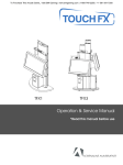
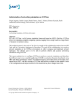
In Fig. 1 is shown the high-level vision of the evaluation platform.
APP
OUTPUT
TERAFLUX
EVALUATION
PLATFORM
APPS
mmul.c
METRICS
speedup
fib.c
PERFORMANCE
fib
# cores
1
2
3
mmul
4
avg
APP
INPUT
Fig. 1 TERAFLUX evaluation platform.
The APPS block represents the applications that researches can feed to the evaluation platform, as
well as other “pipe-cleaner” benchmarks like the ones described in Section 2.3 of this document, or
the ones coming from the activities of WP2. Another important point emerged by the WP2, is a proper
choice of the inputs, in order to be able to show the performance at the “TERADEVICE level” (i.e.,
for at least 1000 complex cores, as discussed in previous deliverables like D7.1, D7.2, D7.3, i.e., 1000
x 109 transistor devices).
The TERAFLUX evaluation platform is the set of common tools available to partners: the extended
simulator (i.e., the extended COTSon, see sections 2.2, 2.4, 2.8, 2.10, and 2.11), compilers (see
section 2.9), the hardware for hosting simulations (see section 3.1), and external tools for power
estimation (see section 2.6), or to easily configure and run the simulator (see section 3.2). The output
block represents the outcome of the benchmarks, while the performance metrics are the set of
statistics that can be obtained when executing benchmarks in the common platform (see sections 2.4
and 2.5). Finally, in this context, the app output is necessary for verifying the application had
executed correctly during the evaluation.
Deliverable number: D7.4
Deliverable name: Report on knowledge transfer and training
File name: TERAFLUX-D74-v10.doc
Page 10 of 50
Project: TERAFLUX - Exploiting dataflow parallelism in Teradevice Computing
Grant Agreement Number: 249013
Call: FET proactive 1: Concurrent Tera-device Computing (ICT-2009.8.1)
2.2 T* Instruction and Built-In Support in the C Language (UNISI, HP)
In the TERAFLUX project, the T* Instruction Set Extensions (ISE) to the x86_64 ISA has been
introduced for managing threads in a dataflow style by means of dedicated hardware units for
executing the custom instructions. In order to experiment with these T* new instructions, we used a
simulation mechanism which overloads a set of unused existing x86 instructions, thus allowing us to
rely on very well tested virtualizer like SimNOW (part of COTSon).
In order to simulate this feature in COTSon and have more flexibility in the register mapping of the
compiler, we overload the semantic of a particular x86_64 instruction, called prefetchnta. This
has the advantage of being a “hint” with no architecturally visible side-effect and does not clobber any
architectural register. From the x86_64 instruction manual [x86]:
prefetchnta m8
where m8 is a byte memory address respecting the x86_64 indexed base + offset format ([x86],
Chapter 2). This instruction is harmless to the core execution, since it is just a “cache hint”: that’s why
we selected it as the mechanism to convey “additional information” into the simulator. It is also rich
enough to support a large encoding space, as well as immediates and registers for T* instructions, as
we describe in more details below. The “additional information” include the T* opcodes and its
parameters, as introduced in D6.1, D6.2, as well as other T* new instructions, besides the 6 original
ones introduced in D7.1, D6.2, whose need became clearer as we started experimenting with more
complex code. Moreover, this instruction is a good match to the compilation tools because it doesn’t
alter any content of the general purpose registers. For example, other user-defined functionalities of
COTSon, and the initial T* implementation, use CPUID (see D7.1, D7.2), which has the unpleasant
side effect of modifying RAX, RBX, RCX, RDX, which causes compiler complexity and unnecessary
spill/restore overhead.
In order to minimize the probability of overloading an instruction used in regular code, we selected as
MOD R/M byte [x86] the value 0x84, which means that m8 specifies a (32-bit) memory address that is
calculated as [%base]+[%index]*2scale+displacement32. The %base, %index register
identifiers and the scale bits (2 bits), are packed in a so-called SIB byte [x86]. displacement32 is
another 4 bytes. In such case, we have a total of 5 bytes (after the opcode and the MOD R/M byte) that
are available for the encoding of T* ISE. We then defined a “magic value” (0x2daf), as a reserved
prefix that indicates a prefetch of 0x2daf0000 (766,443,520 bytes) of a scaled index and base
address, which is not something that has any conceivable use in practice. As a matter of fact, we
tested routine execution of a running system for several billion instructions, as well as all the binaries
shipped with our standard Linux distribution, without any occurrence of that instruction. With the
above choices, the overloaded instruction encoding looks as follows:
0f 18 84 rr XX II af 2d
0 1 2 3 4 5 6 7
where 0x0F18 is the x86 opcode for prefetchnta, 0x84 is the value of the MOD R/M field of
the prefetchnta instruction, 'rr' (1 byte, that was corresponding the SIB byte), 'II' (1 byte) and
'XX' (1byte) are the two remaining byte from the displacement.
Deliverable number: D7.4
Deliverable name: Report on knowledge transfer and training
File name: TERAFLUX-D74-v10.doc
Page 11 of 50
Project: TERAFLUX - Exploiting dataflow parallelism in Teradevice Computing
Grant Agreement Number: 249013
Call: FET proactive 1: Concurrent Tera-device Computing (ICT-2009.8.1)
This allows us to use:
•
The rr value for encoding two x86 registers is used in the T* instruction. We currently chose
to limit the registers to the core set available in both 32b and 64b x86 ISA variants for
simplicity, but we may extend the choice to more 64b registers in the future if the need for
additional registers arises
•
The XX value for encoding the T* opcode (for up to 256 opcodes)
•
The II value for encoding an 8-bit T* immediate, if needed (or other 2 registers like for the rr
field).
Let’s consider, as an example, what happens with a TREAD operation (see D6.2 Table 1) from the
frame memory of a DF-thread, at the “slot” number 5. The compiler should then target such T* builtin. For testing, we also provide a set of C-language built-ins that can be embedded in manual C code,
and would be expressed DF_TREAD(5) as shown here (a more extensive example is provided in
Appendix A for quick reference):
uint64_t a;
a = DF_TREAD(5);
This will then be assembled as:
prefetchnta 0x2daf050e(%rdx,%rdx,1)
and will have a meaning:
TREAD $5, %rdx.
In fact, the corresponding bytes representing the instruction will be:
0F 18 84 12 0E 05 AF 2D
The “container” of the custom instruction is therefore 0xOF1884…AF2D, which is already described
above and is the same for all the custom instructions. The “useful bits” (underlined) are:
•
0x12 specifies the identifier of the destination register of the TREADQI (which is connected
to the destination variable ‘a’ by the gcc-macro expansion),
•
0x0E is the T* opcode for TREADQI (TREAD with immediate value – other currently
experimented opcodes are reported below),
•
0x05, this is the immediate value of the DF_TREAD.
Deliverable number: D7.4
Deliverable name: Report on knowledge transfer and training
File name: TERAFLUX-D74-v10.doc
Page 12 of 50
Project: TERAFLUX - Exploiting dataflow parallelism in Teradevice Computing
Grant Agreement Number: 249013
Call: FET proactive 1: Concurrent Tera-device Computing (ICT-2009.8.1)
In Table 1, we provide the full list of all the T* ISE opcode (i.e., all the possible values for the XX
field) introduced so far in the COTSon simulator.
Table 1 OPCODEs for T* instructions (the instructions with the grey background in this table have been
reported for completeness, but have not yet been fully implmented in the simulator)
OPCODE
0x01
0x02
0x03
0x04
0x05
0x06
0x07
0x08
0x09
0x0A
0x0B
0x0C
INSTRUCTION
TINIT
TSCHEDULE
TREAD
TWRITE
TALLOC
TFREE
TPOLL
TRESET
TSTAMP
TDESTROY
TREADI
TWRITEI
OPCODE
0x0D
0x0E
0x0F
0x10
0x11
0x12
0x13
0x14
0x15
0x16
0x17
0x18
INSTRUCTION
TSCHEDULEI
TREADQI
TWRITEQI
TSCHEDULEP
TESCHEDULEPI
TLOAD
TSTORE
TSTOREQI
TSCHEDULEF
TSCHEDULEFI
TCACHE
TDECREASE
OPCODE
0x19
0x1A
0x1B
0x1C
0x1D
0x1E
0x1F
0x20
0x21
0x22
INSTRUCTION
TDECREASEN
TDECREASENI
TWRITEP
TWRITEPI
TWRITEQPI
TSCHEDULEZ
TWRITE32P
TWRITE32PI
TSTOREP
TSTOREPI
2.2.1 Brief Introduction to COTSon’s Implementation of T*
The set of supported T* ISE, currently experimented, is the following.
•
tschedulepi %tid = %ip, %cnd, $sc: Schedules (conditionally) a thread with address in
register %ip to be executed. Register %cnd holds the predicate. The immediate $sc holds the
synchronization count (0..255). It returns a thread handle in register %tid, or 0 if the predicate
is false1. The %tid is guaranteed to have bits 0..31 at 0 (see TWRITE). Constraint: %tid and
%ip must specify the same register identifier (i.e., the same x86_64 register). For variable sc
or sc > 255, the general version (TSCHEDULEP) is required.
•
tdestroy %dfr: Called at the end of a dataflow thread to signal the TSU the end of a thread
execution and free up thread resources. To reduce simulation polling overhead, the thread is
destroyed internally and returns the address of the next thread (if any available) in register
%dfr; this slightly deviates from the previously defined syntax (just “TDESTROY”). It is a
“peeling” optimization dealing with the (common) case when the queue of ready threads is
not empty, so that there is no need to return to the polling loop.
•
treadqi %res = $im: Reads the 64b value stored at the $im (immediate) offset of the frame of
the self-thread. This is the immediate form with $im < 256. For $im > 255 or variables, use
the general form (TREAD). The offset immediate is expressed in 64b words (i.e. offset=2 is
byte=16).
1
Note: this implementation is slightly different from what described in D6.2 where we proposed to write %tid
only in case of true condition that is tschedule(&%tid, %ip, %cnd, $sc).
Deliverable number: D7.4
Deliverable name: Report on knowledge transfer and training
File name: TERAFLUX-D74-v10.doc
Page 13 of 50
Project: TERAFLUX - Exploiting dataflow parallelism in Teradevice Computing
Grant Agreement Number: 249013
Call: FET proactive 1: Concurrent Tera-device Computing (ICT-2009.8.1)
•
twriteqi %tid, %tval, $im: Writes the 64b value in register %tval to the location at $im
(immediate) offset of the frame of thread %tid. This is the immediate form with $im < 256.
The offset $im is expressed in 64b words (i.e. offset=2 is byte=16). For $im > 255 or variable,
use the general form (TWRITE).
•
talloc and tfree are encoded but semantics to be defined.
The above instructions correspond to the instructions (TSCHEDULE, TDESTROY, TREAD,
TWRITE, TALLOC, TFREE as introduced in the previous deliverable D6.2 (see Table 1).
Additionally, we are currently experimenting with other instructions:
•
tschedule %tid = %ip, %sc: Schedules the thread (unconditionally), while the start address
is located in register %ip. Register %sc contains the synchronization count. tschedule
returns a thread handle in register %tid. By design, we decided to use thread handles
expressed on 32 bits; moreover, for efficiency reasons we store such handles on the 32 most
significant bits of %tid. In this way, we can do standard address arithmetic on thread handles
(e.g., add an offset to obtain the address of an individual element of the thread frame) almost
as if they were addresses. This is the general form used with variable sc or sc > 255. For
immediate version (sc < 256), tschedulei is more efficient.
•
tschedulei %tid = %ip, $sc: Schedules thread (unconditionally) with address in register %ip
to be executed. Immediate $sc holds the synchronization count (0..255). It returns a thread
handle in register %tid. The %tid is guaranteed to have bits 0..31 at 0 (see TWRITE).
Constraint: %tid and %ip must specify the same register identifier (i.e., the same x86_64
register). For variable sc or sc > 255, the general version (TSCHEDULE) is required.
•
tschedulep %tid = %ip, %sccnd: Schedules thread (conditionally) with address in register
%ip to be executed. Register %sccnd packs 'sc' (sync count) and 'cnd' (predicate) as
%sccnd = (sc << 1) + cnd. It returns a thread handle in register %tid, or 0 if the
predicate is false1. The %tid is guaranteed to have bits 0..31 at 0 (see TWRITE). This is the
general form used with variable sc or sc>255. For immediate version (sc < 256), tschedulepi
is more efficient.
•
tschedule %tid = %ip, %sc: Schedules the thread (unconditionally), with the start address in
register %ip. Register %sc contains the synchronization count. tschedule returns a thread
handle in register %tid. By design, we decided to use thread handles expressed on 32 bits;
moreover, for efficiency reasons we store such handles on the 32 most significant bits of
%tid. In this way, we can do standard address arithmetic on thread handles (e.g., add an offset
to obtain the address of an individual element of the thread frame) almost as if they were
addresses. This is the general form used with variable sc or sc > 255. For immediate versions
(constant sc < 256), tschedulei is more efficient.
•
tread %res = %off: Reads the 64b value stored at the offset of %off register of the frame of
the same thread. This is the general form of tread (see also TREADI) with variable (or > 256)
offset.
Deliverable number: D7.4
Deliverable name: Report on knowledge transfer and training
File name: TERAFLUX-D74-v10.doc
Page 14 of 50
Project: TERAFLUX - Exploiting dataflow parallelism in Teradevice Computing
Grant Agreement Number: 249013
Call: FET proactive 1: Concurrent Tera-device Computing (ICT-2009.8.1)
•
treadi %res = $im: Reads the 64b value stored at the $im (immediate) offset of the frame of
the self-thread. This is the immediate form with $im < 256. For $im > 255 or variable, use the
general form (TREAD).
•
twrite %tloc, %tval: Writes the 64b value from register %tval to the location stored in
register %tloc. This is the general form of TWRITE (see also TWRITEI) with variable frame
locations. The %tloc register packs a thread handle (tid) and offset (off), so that %tloc
= tid + off. tid is the return value of the tschedule instruction (and its variants) and is
guaranteed to have the 32 least significant bits set to 0. Hence, tid and off can be used to
construct the thread frame location, by adding the values or doing any other standard address
arithmetic.
•
twritei %tid, %tval, $im: Writes the 64b value in register %tval to the location at $im
(immediate) offset of the frame of thread %tid. This is the immediate form with $im < 256.
The offset $im is expressed in bytes and has to be 64b aligned. For $im > 255 or variable, use
the general form (TWRITE). This is just a different way to write the TWRITEQI.
•
tload %res: Loads the TSU frame values into a locally allocated memory chunk of size %res
that is directly accessible by the thread with standard loads and stores. (Depending on the
implementation of the TSU, it could be simply a no-op).
•
tstore %tloc, %ptr, %len: Writes the values in memory starting from address %ptr and
length %len to the frame location %tloc. The %tloc register packs a thread handle (tid) and
offset (off), so that %tloc = tid + off. The value of tid is the return value of the TSCHEDULE
instruction (and its variants) and is guaranteed to have the 32 least significant bits set to 0, so
that a thread location can be constructed with standard address arithmetic (for example, tid
could be the address of the frame).
•
tstoreqi %tloc, %ptr, $len: Immediate version of the TSTORE operation, with $len a 1-256
immediate.
Other instructions are used in the runtime:
•
tpoll %dfr: called within a worker thread, polls the TSU about work to do work (address of
the dataflow thread to start) is returned in the register %dfr. Used in the runtime and not in the
dataflow program.
•
tinit %nopr, %pstack: initializes a dataflow worker and sets the "no-operation" function in
the register %nopr and a reserved region of memory in register %pstack. The no-operation
function is used to optimize the simulation idle polling loop. The reserved stack is used to
materialize the local frame (by tload, see above) so that it can be used by standard x86 load
and store operation by the compiler. Used in the run-time and not in the dataflow programs.
•
treset %rs, %rn: resets the dataflow execution, freeing all threads and preparing for a new
execution. The register %rs points to a string in memory of length stored in register %rn (for
simulation debugging purposes).
And finally, these instructions are used for debugging and tracing of execution statistics
Deliverable number: D7.4
Deliverable name: Report on knowledge transfer and training
File name: TERAFLUX-D74-v10.doc
Page 15 of 50
Project: TERAFLUX - Exploiting dataflow parallelism in Teradevice Computing
Grant Agreement Number: 249013
Call: FET proactive 1: Concurrent Tera-device Computing (ICT-2009.8.1)
•
tstamp %ts = %buf: collects per-core stats (instr, cycles, idles) in the memory pointed to by
register %buf and returns the current value of simulation nanos in reg %ts. Can be used to
address execution statistics (in a much more precise way than using performance counters)
from a guest program.
2.3 New T* Benchmarks (UNISI)
By exploiting the T* ISE support for the C-language introduced in the section 2.1, new benchmarks
have been implemented for running in the COTSon simulator. The Matrix Multiplier benchmark is
already available in the COTSon repository, while the Radix Sort benchmark is going to be released in
the near future.
2.3.1 Matrix Multiplier
The matrix multiplication algorithm chosen for the T* C-like implementation is the blocked matrix
multiplication version, in which the result matrix C = A·B is recursively constructed as:
s
C ab = ∑c =1 Aac ⋅ Bcb
where Cab represents a sub-block of the result matrix. The input matrices A and B are required to be
square for simplicity, and defined as:
A= {Aij }
B = { Bij }
The input parameters that the algorithm needs for execution are two integers s and np, both required
being power of 2:
•
s – number of rows and columns of the square matrices A, B and C;
•
np – total number of partitions (blocks).
For example, running the application with s=32 and np=4, will perform a multiplication of 2x2
blocked matrices, in which each block is composed by 16x16 elements. Details on the structure of the
dataflow version of this benchmark are reported in Appendix A.
The source code of the matrix multiplier algorithm is available to the TERAFLUX partners in the
public SOURCEFORGE website [SF]. We report the code for quick reference in the Appendix A.
2.3.2 Other Benchmarks
A Dataflow version of the Recursive Fibonacci application has been implemented in C using the
built-ins introduced in Section 2.2, similarly to the Matrix Multiplier described in previous section.
The well-known Radix Sort benchmark, which is one of the kernel application included in the
SPLASH-2 suite [Cameron95], has been also developed in the T* C-like style for our experiments.
The implementation of this algorithm is still ongoing because it requires some protection mechanism
Deliverable number: D7.4
Deliverable name: Report on knowledge transfer and training
File name: TERAFLUX-D74-v10.doc
Page 16 of 50
Project: TERAFLUX - Exploiting dataflow parallelism in Teradevice Computing
Grant Agreement Number: 249013
Call: FET proactive 1: Concurrent Tera-device Computing (ICT-2009.8.1)
for managing concurrent accesses to shared data. Since in the TERAFLUX project the Transactional
Memory (TM) is supposed to be adopted for this purpose, the implementation of this benchmark will
be completed in the near future by exploiting the new TM feature added by the UNIMAN partner to
the COTSon platform.
2.4 Single Node T* Tests (UNISI)
In order to show the potential of the implementation of T*, we show here the possibility to collect
some statistics (number of Dataflow Threads that are executing, running and waiting) related to the
execution of some benchmarks on the modified COTSon platform.
We selected for this sake Matrix Multiplier described in Section 2.2.1 or the Recursive Fibonacci
(already introduced and described in previous deliverables D6.1, D6.2) as “pipe-cleaners”. The first
step has been to code those examples by hand, in order to allow the WP4 to have some simple
examples to target the proposed T* instructions.
On the simulator side, the efforts in this year had been to support properly the execution of the
Dataflow Thread (this is coded in the publicly available modules TSU, TSU2, TSU3 on the Source
Forge website)
DF Threads can be either waiting to become ready (i.e. their synchronization count has not reached
zero), or already in the ready queue, waiting for execution once some core becomes available. In the
single node experiments, we varied the number of cores from 1 to 32. In this context, simulations
have been successfully performed.
4 cores
# o f th r e a d s (th o u d a n d s )
1600
1400
1200
1000
800
600
400
200
0
8 cores
1600
TH_WAITING
TH_READY
TH_RUNNING
TOTAL
#of threads (thousands)
1400
1200
1000
800
600
400
200
0
0
2
4
6
8
10
12
14
16
0
18
2
4
6
Clock cycles (millions)
16 cores
1600
10
12
14
16
18
12
14
16
18
32 cores
1600
1400
# o f th re a d s ( th o u s a n d s)
8
Clock cycle (millions)
1400
#of threads (thousands)
1200
1000
800
600
400
200
1200
1000
800
600
400
200
0
0
0
2
4
6
8
10
12
14
16
18
0
2
Clock cycle (millions)
4
6
8
10
Clock cycle (millions)
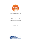
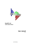
Fig. 2 Fibonacci(35): number of threads in four single-node configurations
Deliverable number: D7.4
Deliverable name: Report on knowledge transfer and training
File name: TERAFLUX-D74-v10.doc
Page 17 of 50
Project: TERAFLUX - Exploiting dataflow parallelism in Teradevice Computing
Grant Agreement Number: 249013
Call: FET proactive 1: Concurrent Tera-device Computing (ICT-2009.8.1)
In the following, results of the execution of the Fibonacci benchmark are discussed. In particular, Fig.
2 shows the number of threads waiting, ready and running in the system during the execution of the
recursive computation of the 35th term of the Fibonacci series, targeting four different single node
configurations (4, 8, 16 and 32 cores). The figure highlights two aspects. First, the maximum number
of threads created in the system is 1.5M, over all different configurations. Second, the execution time
is reduced by a half when the number of cores in the node doubles.
These results show that the COTSon simulator is now able to support the T* execution model (a
dataflow execution model) achieving almost perfect scaling. However, the timing model still has to be
tuned up by connecting the existing memory hierarchy timing models of COTSon to the T*
components: such activity is ongoing and briefly described in section 2.3.1. In Fig. 3, we also show a
“zoom” of the bottom part of the thread graphs. For each configuration, except for the “startup” and
“ending” phases, we observe that there is always a number of running DF-Threads equal to number of
cores, demonstrating that the execution paradigm is always able to load the system.
16
7
14
6
12
5
10
#of threads
#of threads
4 cores
8
4
3
8 cores
TH_WAITING
TH_READY
TH_RUNNING
8
6
2
4
1
2
0
0
0
2000000 4000000 6000000 8000000
1E+07
1,2E+07 1,4E+07 1,6E+07 1,8E+07
0
2E+07
1000000 2000000 3000000 4000000 5000000 6000000 7000000 8000000 9000000
60
25
50
20
40
#of threads
#of thre ads
16 cores
30
15
32 cores
30
10
20
5
10
0
1E+07
Clock cycle
Clock cycle
0
0
500000 1E+06 2E+06 2E+06 3E+06 3E+06 4E+06 4E+06 5E+06 5E+06
0
500000
Clock cycle
1000000
1500000
2000000
2500000
3000000
Clock cycle
Fig. 3 Fibonacci(35): number of threads (zoomed detail of the previous Figure)
2.4.1 T* Timing Model
Currently, the TSU implementation already provides functional execution for all T* instructions. In
this section, we describe the implementation efforts for the timing model within the simulator, which
assumes the baseline architecture described in D6.3 for the TERAFLUX DTS (Distributed Thread
Scheduler).
For explaining the current methodology, we assume the existence of a component still under research
in the Architecture workpackage, which is the DF-Frame cache.
Deliverable number: D7.4
Deliverable name: Report on knowledge transfer and training
File name: TERAFLUX-D74-v10.doc
Page 18 of 50
Project: TERAFLUX - Exploiting dataflow parallelism in Teradevice Computing
Grant Agreement Number: 249013
Call: FET proactive 1: Concurrent Tera-device Computing (ICT-2009.8.1)
The implementation of the timing model is organized as shown in the Fig. 4. The execution flow is
managed as follows:
•
During the execution, T* instructions and memory accesses are dropped from SimNow into
COTSon.
•
The Filter component filters all T* memory accesses to DF-Frames by passing them to the
TSU in order to model the DF-Frame cache, DF-Frame memory, and all queue structures. All
other instructions (i.e., the ones that are part of the regular x86_64 ISA) are passed directly to
the COTSon Timer, which already implement the timing model for non T* instructions.
•
Inside the TSU, the DF-Frame memory and the DF-Frame cache are modeled. For example,
we can assume that the access latency to DF-Frame cache is equal to Core Level Cache
Hierarchy (CL$H in the Architectural Template presented in D6.2, Figure 1), and the latency
access to physical DF-Frame memory is equal to normal memory access.
•
The latency feedback for these accesses in the TSU is passed to the timer in COTson.
Fig. 4 Timing model for the T* execution
In order to provide the COTSon user with an easy way to model the architecture, for example with the
purpose of exploring different configurations which are characterized by different timings, we define
the size of DF-Frame cache, DF-Frame memory, queues in a configuration file (e.g. the tsu.lua file)
which is processed by COTSon.
In the current simulator integration, we have implemented the filtering of T* instructions and memory
accesses into TSU. The next steps will be modeling DF-Frame memory and DF-Frame cache.
2.5 Multi-Node T* Tests (UNISI)
The simulation environment described in section 2.3 created the basis for single node simulations (we
decided not to exceed the size of 32 cores per node – current commercial processors like the AMD
6200 encompass 16 cores per processor). In order to simulate systems with a higher number of cores,
the number of nodes of the target machine must be increased. In particular, if we want to simulate a
Deliverable number: D7.4
Deliverable name: Report on knowledge transfer and training
File name: TERAFLUX-D74-v10.doc
Page 19 of 50
Project: TERAFLUX - Exploiting dataflow parallelism in Teradevice Computing
Grant Agreement Number: 249013
Call: FET proactive 1: Concurrent Tera-device Computing (ICT-2009.8.1)
system with say 1024 cores (target for this project as presented in previous deliverables and in
particular in D7.2), we may need at least 32 nodes.
Extending COTSon in order to allow many node simulations with T* support has been performed by
UNISI, with the support of HP. Currently, the TSU model is able to perform thread scheduling among
many nodes. It has to be tuned up by connecting the timing models of the several existing components
(like caches, memory, to the TSU models). We plan to complete the multi-node case in the next year.
In the following, we provide some insights on the framework, and show preliminary results of
Fibonacci and Matrix Multiplier running on target machine up to 1024 cores.
Fig. 5 The structure of the framework for multi-node simulation as it is running on our simulation host.
2.5.1 Framework design
A scheme of the framework for multi-node simulation is shown in Fig. 5. The access to the DF-Frame
information among nodes is provided through shared memory allocated on the host machine. Such
shared data structures hold 1) a Circular Queue for holding the continuations of created DF-Threads,
which are not ready for execution, and 2) the Ready Queue for those threads whose synchronization
count has reached zero. A Scheduler is responsible for managing properly these queues. In the current
implementation, the Scheduler distributes the ready DF-Threads among nodes following a simple
round-robin policy. Nodes can access the DF-Frame Memory through a message queue to a high-level
entity we called Manager. Such manager is responsible for allocating-deallocating DF-Frame Memory
dynamically.
Deliverable number: D7.4
Deliverable name: Report on knowledge transfer and training
File name: TERAFLUX-D74-v10.doc
Page 20 of 50
Project: TERAFLUX - Exploiting dataflow parallelism in Teradevice Computing
Grant Agreement Number: 249013
Call: FET proactive 1: Concurrent Tera-device Computing (ICT-2009.8.1)
A timing model for the multi-node framework will be designed and developed in the next period, as
an extension to the single-node timing model, and is currently under development.
2.5.2 Demonstration of multi-node capability of the new distributed scheduler
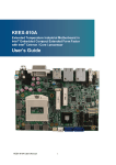
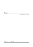
Fig. 6 shows the speedup – with respect to the single core case – of the execution time for both
Fibonacci (computation of 40) and Matrix Multiply (with matrix size of 512). We simulated a number
of cores from 1 to 1024, in steps of powers of 2: in the configurations up to 32 cores the systems are
single node, from 64 to 1024 cores each simulation run on systems with many nodes, each node
hosting 32 cores.
MATRIX MULTIPLY
FIBONACCI
1024
512
256
128
64
32
16
8
4
2
1
Speedup
Speedup
1024
512
256
128
64
32
16
8
4
2
1
FIB (40)
1
2
4
8
16
32
64
128
Number of cores
256
512 1024
MMUL(512)
1
2
4
8
16
32
64
128
Number of cores
256
512
1024
Fig. 6 Multi-node simulation: Fibonacci, with input set to 40, and Matrix Multiply, with matrix
size 512x512, partitioned in a number of blocks equal to the number of cores
As we can see, we have reached the ability to simulate the dataflow execution model not only in the
single core but also across nodes, without changing the programming model or execution model when
passing from the single node case to the multi-node case. Of course, we need to tune up the system in
order to evaluate the sensitivity to the availability of resources like bandwidth and memory controllers
(as explored initially in the deliverables D2.1, D2.2 regarding the Application work package).
In the case of the matrix multiply benchmark, we start to see some loss of scalability after 512 cores:
this is due to the lack of parallelism as we choose too small a data set for this experiment. As a side
note, we can see that the simulator is also able to catch such behaviors.
2.6 Power estimation using McPAT (UNISI)
Power estimation along with temperature and reliability is an important metric that enables the
envisioned architecture to schedule DF-Threads with the aims of improving the overall resiliency of
the system. This has been extensively discussed in the previous deliverable D7.3. Here we briefly
describe how this mechanism has been extended from an off-line to an on-line methodology. This is
necessary to drive the scheduling actions during the program execution.
Looking at the simulation level, power estimation is obtained with the use of an external tool called
McPAT [MCPAT09]. McPAT has been developed by HP with the ability of estimating power
consumption, timing and area of a given microarchitecture. Specifically, McPAT implements an
internal model to compute the power consumption based on the activity within the modeled
microarchitecture. The activity refers to the instructions executed by the modeled systems, and in
Deliverable number: D7.4
Deliverable name: Report on knowledge transfer and training
File name: TERAFLUX-D74-v10.doc
Page 21 of 50
Project: TERAFLUX - Exploiting dataflow parallelism in Teradevice Computing
Grant Agreement Number: 249013
Call: FET proactive 1: Concurrent Tera-device Computing (ICT-2009.8.1)
particular to the internal structures that are activated during the execution of each instruction.
Combining these statistics with a description of the specific modeled microarchitecture, the tool can
estimate static and dynamic power consumption components (e.g., power consumption for the cache
memories, power consumption for the cores, etc.), timing and area utilization.
In order to enable the simulated system to schedule DF-threads according to policies that count for the
current power consumption, as well as the temperature and the reliability level, the system must be
equipped with a power, fault and temperature measurement system. From the perspective of the
simulator, this goal can be obtained by integrating the McPAT tool within the COTSon simulator.
2.6.1 Off-line vs. on-line Power estimation
As a first step towards a complete integration, McPAT has been enabled to run at the end of the each
heartbeat, computing power estimation on a periodic base. Periodic power estimation is obtained
storing execution statistics coming from the COTSon simulator at every heartbeat. The heartbeat
represents the internal interval used by the simulator to store the statistics (the interval size is not
fixed). In the off-line approach, McPAT is run at the end of the COTSon simulation: it processes all
recorded heartbeats in sequence at the end of the execution of the program. On the contrary, in the online approach, McPAT is run during the simulation, right after a heartbeat has been produced, while
the program is still running.
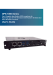
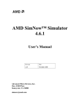
Fig. 7 shows the current tool chain used to estimate power consumption with an off-line/on-line
processing and some first sample of output.
HEARTBEATS
1—5
6—10
11—15
16—20
CPU <cpu0>:
3000 MHz 3000 MHz 3000 MHz 3000 MHz
Core clock
518001021 cc 741501468 cc 988501962 cc 742001469 cc
Cycles
172.667 msec 247.167 msec 329.501 msec 247.334 msec
Time
Subthreshold Leakage power 2.39913 W 2.39913 W 2.39913 W 2.39913 W
0.0054596 W 0.0054596 W 0.0054596 W 0.0054596 W
Gate Leakage power
2.4045896 W 2.4045896 W 2.4045896 W 2.4045896 W
Total Leakage power
Runtime Dynamic power 0.269286 W 0.269339 W 0.269316 W 0.269265 W
2.6738756 W 2.6739286 W 2.6739056 W 2.6738546 W
Total power
CPU <cpu1>:
3000 MHz 3000 MHz 3000 MHz 3000 MHz
Core clock
518001021 cc 741501468 cc 988501962 cc 742001469 cc
Cycles
172.667 msec 247.167 msec 329.501 msec 247.334 msec
Time
Subthreshold Leakage power 2.39913 W 2.39913 W 2.39913 W 2.39913 W
0.0054596 W 0.0054596 W 0.0054596 W 0.0054596 W
Gate Leakage power
2.4045896 W 2.4045896 W 2.4045896 W 2.4045896 W
Total Leakage power
Runtime Dynamic power 0.268092 W 0.268093 W 0.268093 W 0.268092 W
2.6726816 W 2.6726826 W 2.6726826 W 2.6726816 W
Total power
CPU <cpu2>:
3000 MHz 3000 MHz 3000 MHz 3000 MHz
Core clock
518001021 cc 741501468 cc 988501962 cc 742001469 cc
Cycles
172.667 msec 247.167 msec 329.501 msec 247.334 msec
Time
Subthreshold Leakage power 2.39913 W 2.39913 W 2.39913 W 2.39913 W
0.0054596 W 0.0054596 W 0.0054596 W 0.0054596 W
Gate Leakage power
2.4045896 W 2.4045896 W 2.4045896 W 2.4045896 W
Total Leakage power
Runtime Dynamic power 0.268092 W 0.268093 W 0.268093 W 0.268092 W
2.6726816 W 2.6726826 W 2.6726826 W 2.6726816 W
Total power
CPU <cpu3>:
3000 MHz 3000 MHz 3000 MHz 3000 MHz
Core clock
518001021 cc 741501468 cc 988501962 cc 742001469 cc
Cycles
172.667 msec 247.167 msec 329.501 msec 247.334 msec
Time
Subthreshold Leakage power 2.39913 W 2.39913 W 2.39913 W 2.39913 W
0.0054596 W 0.0054596 W 0.0054596 W 0.0054596 W
Gate Leakage power
2.4045896 W 2.4045896 W 2.4045896 W 2.4045896 W
Total Leakage power
Runtime Dynamic power 0.268092 W 0.268093 W 0.268093 W 0.268092 W
2.6726816 W 2.6726826 W 2.6726826 W 2.6726816 W
Total power
All CPU total power:
Dynamic
Leakage
total
1.073562 W 1.073618 W, 1.073595 W, 1.073541 W,
9.6183584 W 9.6183584 W, 9.6183584 W, 9.6183584 W,
10.6919204 W 10.6919764 W 10.6919534 W 10.6918994 W
Deliverable number: D7.4
Deliverable name: Report on knowledge transfer and training
File name: TERAFLUX-D74-v10.doc
Page 22 of 50
Project: TERAFLUX - Exploiting dataflow parallelism in Teradevice Computing
Grant Agreement Number: 249013
Call: FET proactive 1: Concurrent Tera-device Computing (ICT-2009.8.1)
CPU 0 Power in 4 Periods
Total Leakage power
Power (W)
3
2.5
2
1.5
1
0.5
0
172.667
247.167
329.501
247.334
Duration (ms)
Fig. 7 Power estimation sample outputs.
The off-line power estimation process starts with a complete simulation running on the COTSon
simulation infrastructure. During the simulation, all the relevant statistics are collected through the
internal timer components of the simulator within a SQL local database. The database also contains
the main configuration parameters of the simulated machine. Simulation statistics are organized on a
per-heartbeat basis. At the end of each heartbeat the content of the database is parsed in order to
provide, for each heartbeat, an XML-based configuration file for the McPAT tool. The XML
configuration file contains both the main statistics for the current heartbeat, and the machine
architecture description. Hence, for each heartbeat, the McPAT tool extracts a power consumption
estimation. As shown in, in the case of the on-line power estimation, the set of power estimation
values is stored back in the database. This allows the TSU to properly schedule the DF-Threads in
order to respect the power/temperature and reliability (see also Section 2.10 in this deliverable and
Deliverable D5.3) constraints, and their correlation with power consumption. Similarly to the off-line
approach, the XML configuration file is generated by the McPAT configuration generator script at
every heartbeat. Finally, in this case the same set of power consumption values can be used to respect
the power profile of the simulated machine.
Deliverable number: D7.4
Deliverable name: Report on knowledge transfer and training
File name: TERAFLUX-D74-v10.doc
Page 23 of 50
Project: TERAFLUX - Exploiting dataflow parallelism in Teradevice Computing
Grant Agreement Number: 249013
Call: FET proactive 1: Concurrent Tera-device Computing (ICT-2009.8.1)
2.7 Execution of User Level DDM on COTSon (UCY)
Within the context of WP7 we have been working on the execution of DDM applications using our
user-level DDM TSU runtime. With our first implementation reported earlier we were able to execute
on single node COTSon instances. Within this year we have extended the TSU to support execution
on distributed systems. Our first attempt to execute on a multi-node COTSon setup did not turn out
successful due to problems with the data communication support across multiple COTSon nodes.
We developed a small benchmark program for the communications layer and we were able to identify
that COTSon did not progress when the user sends messages larger than 2KB. To overcome this issue
we developed an intermediate communication layer in the TSU network unit that accepts messages of
any size and splits them into smaller packets to achieve successful communication. As it is shown in
Fig. 8 we have managed to successfully execute a DDM application using 4 nodes on COTSon with
the user level TSU.
This configuration was compiled on the tfx2 machine (i.e. one of the simulation hosts provided by
UNISI with 48 cores and 256 GB of shared memory), provided by UNISI.
Fig. 8 Running DDM on COTSon, with four nodes
Deliverable number: D7.4
Deliverable name: Report on knowledge transfer and training
File name: TERAFLUX-D74-v10.doc
Page 24 of 50
Project: TERAFLUX - Exploiting dataflow parallelism in Teradevice Computing
Grant Agreement Number: 249013
Call: FET proactive 1: Concurrent Tera-device Computing (ICT-2009.8.1)
Fig. 9 Blocked Matrix Multiply running on a four cpu machine
2.8 Integrating DDM TSU into COTSon (UCY)
As a continuation of the work described in the previous Section, we have integrated the DDM TSU
into COTSon by using as template the tsu2 code provided in the TERAFLUX public repository
(https://cotson.svn.sourceforge.net/svnroot/cotson/branches/tflux-test/tsu2/) and the TSU++ version of
the DDM system. The tsu2 operates as an intermediate API to provide communication between the
user application and the TSU unit.
To validate this implementation of the TSU, we have executed the blocked matrix multiply
benchmark for 4 workers on a single machine (see Fig. 9).
We have used a single queue to store threads that are ready for execution and a FIFO policy for
scheduling. The TSU does not operate in busy-wait mode but instead it is event-driven execution,
which seems to make simulation faster. This configuration was compiled on the tfx2 machine (see
above).
2.9 GCC Backend and OpenStream Experiments on COTSon (INRIA)
The TERAFLUX backend compiler has been maturing over the course of the third year of the project.
It compiles OpenStream programs (data-flow streaming extensions of OpenMP) to T* intrinsic
functions, themselves compiled to the T* ISA. The code generation pass has been developed as a
middle-end pass in GCC 4.7.0, operating on three-address GIMPLE-SSA code. The traditional
Deliverable number: D7.4
Deliverable name: Report on knowledge transfer and training
File name: TERAFLUX-D74-v10.doc
Page 25 of 50
Project: TERAFLUX - Exploiting dataflow parallelism in Teradevice Computing
Grant Agreement Number: 249013
Call: FET proactive 1: Concurrent Tera-device Computing (ICT-2009.8.1)
compilation flow is being modified according to a specialized adaptation of the built-in-based, late
expansion approach described in D4.2 (first year deliverable). See also [Li12, Li12b]. Built-ins are
used both to convey the semantics of input and output clauses in streaming pragmas to the compiler
middle-end, and to capture the semantics of efficiency languages such as HMPP, StarSs/OMPSs and
TFLUX. More details can be found in [Pop13] and Deliverable D4.1).
As part of the training and internal dissemination activities, a step by step OpenStream tutorial has
been designed and distributed with the OpenStream repository. It consists of a set of 15 thoroughly
commented examples illustrating all the features of the language.
The applications ported to OpenStream in WP2 have been distributed together with the OpenStream
source code. They have also been packaged as stand-alone benchmarks with multiple data sets and
auto-tuning scripts to facilitate the adaptation of the grain of parallelism to the target. The current list
of distributed OpenStream programs is: cholesky, fmradio, seidel, fft-1d, jacobi, strassen, fibo,
knapsack, matmul, bzip2 (SPEC CPU 2000) and ferret (PARSEC). For some of these programs,
multiple versions are provided, to compare data-flow-style, Cilk/join-style, and barrier-style
implementations.
All OpenStream applications are supported by the software run-time implementation of T*. In
addition, most applications run on COTSon when compiled using the hardware-ISA branch of the
TERAFLUX compiler (i.e., the SourceForge public repository [SF]). The only problematic ones are
the Cilk/join and barrier-style variants of the benchmarks that make use of the lastprivate or taskwait
constructs of OpenStream. These currently cannot be implemented using T* (the compiler makes use
of scheduling and stack manipulation mechanisms not supported by the tsu2 branch of COTSon). This
is not a major issue as the data-flow-style programs compile and run properly, but for completeness
and to facilitate the implementation of larger applications, we are working on an extension of the T*
ISA to support these constructs directly.
At this time, the TERAFLUX memory model is in progress in COTSon. A preliminary (formal)
specification exists for Owner-Writable Memory (OWM, see D7.1) regions [Gin12] and UNIMAN
implemented TM in COTSon, but the former is not yet implemented and the latter has not been
merged with the tsu2 and tsu3 branches of the simulator. As a result, only pure data-flow benchmarks
are currently able to scale to 1024 cores, or to run on multiple nodes in general. Unfortunately, the
current compilation flow for OpenStream makes use of intermediate/proxy data structures for runtime dependence testing. This is necessary to implement the sliding window semantics of the
language's streams, and to support the rich region-based dependences of StarSs/OMPSs. Because of
this, OpenStream programs currently run on a single node only, and will stay that way until the
memory model is implemented in the simulator. To cope with this limitation, and also to enable
additional performance comparisons, a low-level intrinsic/builtin interface to T* has been
implemented in the TERAFLUX back-end compiler. This interface retain a C syntax and semantics,
abstracting the low-level optimization details of the compilation flow, but it requires the programmer
to think directly in terms of data-flow threads, carrying the frame meta-data explicitly. Still, it allows
pure data-flow programs to be written and to scale on the full architecture.
Technical information, source code, tutorial examples, and benchmarks are available online and
updated regularly: http://www.di.ens.fr/OpenStream.html.en.
Deliverable number: D7.4
Deliverable name: Report on knowledge transfer and training
File name: TERAFLUX-D74-v10.doc
Page 26 of 50
Project: TERAFLUX - Exploiting dataflow parallelism in Teradevice Computing
Grant Agreement Number: 249013
Call: FET proactive 1: Concurrent Tera-device Computing (ICT-2009.8.1)
2.10 Double Execution and Thread Restart Recovery in a Single Node
(COTSon Modules) (UAU, HP)
In this section, we will give an overview of the implementation details of the FDU subsystem, Double
Execution, and Thread Restart Recovery in the TERAFLUX simulator. For more details about the
Double Execution and Thread Restart Recovery mechanisms, please refer to Deliverable D5.3, which
describes the technical implications of Double Execution and the thread restart recovery for the
TERAFLUX architecture. The enhanced source code is publicly available in the tflux-test branch of
the public COTSon SourceForge repository.
All simulator extensions in this section are based on the functional tsu2 implementation provided by
the partners HP and UNISI. Please note that at this point of the simulator integration there is neither a
functional differentiation between D-FDU and L-FDU nor between the D-TSU and L-TSU. Hence,
we refer just to FDU and TSU, respectively.
2.10.1 FDU subsystem in COTSon
The FDU subsystem uses the periodic AMD SimNow timer callback (FDU::call_periodic).
The FDU itself is, similar to the TSU, implemented as a singleton object.
At each periodic call, the monitoring subsystem generates heartbeats and pushes them into the
FDU's monitoring queue. After all cores have pushed their heartbeats, the FDU singleton processes
them in its M(onitor) A(analyse) P(lan) E(execute) cycle, stores the information in its knowledge
base, and updates its core records. For more details on the MAPE cycle and the FDU internals please
refer to the Deliverables D5.1, D5.2, and D6.2.
The current D-FDU implementation maintains interfaces to two TERAFLUX device types:
1. The cores within a node
2. The TSU (used version: tsu2)
The FDU/core interface implements a FIFO queue (message_queue), shared between the cores
and the FDU. The FDU/TSU interface is a function (get_core_record()) exposed by the FDU
singleton. This function is called by the node’s TSU and returns the latest core record for a given core
ID, enclosing information about the current core performance, its reliability value, and wear-out of a
core. Whenever the TSU tries to schedule a new thread, it queries the FDU for a new core record and,
if required, adjusts its scheduling policy.
2.10.2 Double execution and Recovery Support
Double Execution and Thread Restart Recovery both require an execution free from side-effects. To
ensure this in the TERAFLUX simulator, we extended the dthread data structure in the TSU by a
per-thread write-buffer wbuf. This write-buffer is created along with a dthread object when the
TSU has received a TSCHEDULE operation. After the thread becomes ready to execute, all
subsequent TWRITEs of this thread will be redirected to the wbuf data structure. The TWRITEs of
the leading thread are held in the write-buffer until both the leading thread and the trailing thread
executed their TDESTROY instructions. Additionally, the CRC-32 signature, incorporating the target
Deliverable number: D7.4
Deliverable name: Report on knowledge transfer and training
File name: TERAFLUX-D74-v10.doc
Page 27 of 50
Project: TERAFLUX - Exploiting dataflow parallelism in Teradevice Computing
Grant Agreement Number: 249013
Call: FET proactive 1: Concurrent Tera-device Computing (ICT-2009.8.1)
thread ID, the target address and the data of each single TWRITE, is calculated and stored in the FDU
for both the trailing and the leading thread.
When the TSU receives a TDESTROY instruction, it checks whether the redundant thread has
finished its execution by verifying the thread’s current state. If the redundant thread is still running,
the TSU marks the finished thread as ready-to-check. Otherwise, the TSU calls the FDU singleton to
indicate that both threads have finished their execution. The FDU in turn compares the stored CRC-32
signatures and returns a Boolean result indicating a fault-free execution (true) or a faulty execution
(false).
Additionally, partner HP extended the baseline TSU implementation to support speculative thread
creation. Speculative thread creation means that dthread objects created by a potentially faulty
thread are tagged as speculative and can be discarded when the FDU detects a fault in the parent
thread. To enable the elimination of speculative threads in case of a fault, each speculative thread
stores the parent ID of its creator in its dthread object.
As described in Deliverable D5.3, the write-buffer and the speculative thread creation are required to
ensure the execution without side-effects and therefore enable Double Execution and Thread Restart
Recovery. Our Double Execution implementation and Thread Restart Recovery mechanism fully
support the T* instruction set, as described in Deliverable D6.2.
Double Execution and speculative thread support can be activated in the COTSon configuration file
by setting the following options:
options = {
tsu_speculative_threads=true #Activate speculative thread creation
double_execution=true
#Activate Double Execution
}
2.11 High Level Fault Injection Technique (COTSon Modules) (UAU)
To investigate the thread execution performance of Double Execution and Thread Restart Recovery
mechanism in presence of failures, we extended the baseline TSU implementation by a failure
injection mechanism. Currently, the failure injection mechanism assumes a constant failure rate λ per
core. However, we will incorporate more complex failure distributions in the last year of the project.
From the constant failure rate λ [Koren07], we derive the reliability R of a core at time ∆t with
t
R(∆t) = e−λ∆
where ∆t is the duration since the last failure occurred in this core. A core’s reliability value is
updated when the core executes a thread and issues a TDESTROY or TWRITE instruction. The TSU
subsequently generates a random number rand
has suffered from a defect:
, with 0 ≤ rand ≤ 1 and verifies whether the core
bool faulty = random > reliability;
Deliverable number: D7.4
Deliverable name: Report on knowledge transfer and training
File name: TERAFLUX-D74-v10.doc
Page 28 of 50
Project: TERAFLUX - Exploiting dataflow parallelism in Teradevice Computing
Grant Agreement Number: 249013
Call: FET proactive 1: Concurrent Tera-device Computing (ICT-2009.8.1)
We distinguish between two failure injection modes:
•
•
Bit flip failures and
thread failures
For the bit flip injection the TSU determines the reliability on each TWRITE and checks whether the
core became faulty. If the core has suffered from a fault, one random bit within the TWRITE
parameters is flipped.
For the thread failure injection, the TSU checks the reliability during each TDESTROY operation. If
the core has suffered from a defect during thread execution, the TSU tags the thread as defective and
starts recovery actions.
The failure injection functionalities are managed in the COTSon configuration file by activating the
core_failure_injection=true parameter, while the failure rate per second can be
adjusted by the core_failure_rate parameter. Finally, the failure injection mode is selected by
the failure_injection_mode parameter. Fig. 10 shows exemplary the performance
degradation induced by thread failure injection and thread restart recovery for Fibonacci(40). More
results using the failure injection mechanism can be found in Deliverable D5.3.
Fig. 10 Performance degradation of Fibonacci(40) using thread failure injection with failure rates per core of
10/s and 100/s
Deliverable number: D7.4
Deliverable name: Report on knowledge transfer and training
File name: TERAFLUX-D74-v10.doc
Page 29 of 50
Project: TERAFLUX - Exploiting dataflow parallelism in Teradevice Computing
Grant Agreement Number: 249013
Call: FET proactive 1: Concurrent Tera-device Computing (ICT-2009.8.1)
2.12 Transactional Memory Support in COTSon (UNIMAN)
This section describes the implementation of Transactional Memory (TM) on SimNow and COTSon.
Although COTSon provides the timing model for our simulations, we cannot control the flow of the
program (as required in TM implementation) from within COTSon. Correctly dealing with
transactional execution and transaction aborts requires a TM module for SimNow which exists outside
COTSon.
There are two interfaces provided by AMD in order to interact with SimNow: Analyzer interface and
Monitor interface. The Monitor interface is much faster than the Analyzer interface but allows less
interaction with execution. If we intercept memory accesses, as required during Transactions, then
Analyzer interface runs 40-50X slower than the monitor interface. This performance advantage was
why the Monitor interface was chosen for COTSon.
For our TM implementation, two important features are needed. Intercepting memory accesses to
detect conflicts, and saving and then restoring register state of the processors to correctly deal with
aborts. Further, to arrive at realistic performance estimates, existing performance models in COTSon
need to be extended with Transactional behavior. For this reason we will be using both the interfaces
together, when using transactions.
2.12.1 Functional Transaction Support
Functional support in a SimNow analyzer module keeps track of read and write sets, detects conflicts
and performs the necessary cleanup in case of aborts. At this level, our system can model both eager
and lazy versioning, and eager and lazy conflict detection. The behavior of the TM is described in
more detail in Deliverable D6.3. During the implementation and testing of this module, several bugs
were identified in SimNow. These were addressed by AMD and fixed in an NDA version2 of
SimNow. This means that the TM module works correctly with the NDA version, but not the current
public release.
The functional TM support has been made available to TERAFLUX partners and the wider
community through a branch in the COTSon SourceForge repository. Further, a subset of the STAMP
(kmeans, vacation) benchmarks is included for testing and demonstration.
2.12.2 Adding timing support with COTSon
Timing models for Transactional Memory have been added in a separate branch of COTSon. This
branch includes models for two TM systems. Therefore, the relevant contributions are:
•
The first is a simple bus based broadcast implementation.
•
The second is a more scalable distributed system. This involved adding timing support for a
distributed directory based cache coherence protocol.
•
A network model has been implemented in place of the standard bus simulation present in
COTSon, leading to a more realistic model for large scalable systems.
2
To get this version, the interested partner has to sign a Non Disclosement Agreement with AMD. This has not
yet been possible for all Partners.
Deliverable number: D7.4
Deliverable name: Report on knowledge transfer and training
File name: TERAFLUX-D74-v10.doc
Page 30 of 50
Project: TERAFLUX - Exploiting dataflow parallelism in Teradevice Computing
Grant Agreement Number: 249013
Call: FET proactive 1: Concurrent Tera-device Computing (ICT-2009.8.1)
Scalable Transactional Memory mechanisms have been built on top of these protocols. This timing
support is separate from the functional simulation in the SimNow analyzer module described above,
but needs to be used in conjunction with it.
On the level of timing simulation, the TM systems supported are lazy-lazy implementations. Further
details are described in Deliverable 6.3.
As with the functional module, TM timing support is available in a branch on Sourceforge. This
includes the TM models themselves, distributed directory based cache coherence, network simulation,
and the scripts, documentation and tests to go with these. Similar to SimNow, this work exposed
several bugs in COTSon, for which we have contributed fixes in conjunction with our partners at HP.
Deliverable number: D7.4
Deliverable name: Report on knowledge transfer and training
File name: TERAFLUX-D74-v10.doc
Page 31 of 50
Project: TERAFLUX - Exploiting dataflow parallelism in Teradevice Computing
Grant Agreement Number: 249013
Call: FET proactive 1: Concurrent Tera-device Computing (ICT-2009.8.1)
3 Development and Simulation environment and supports
The adoption of architectural simulators has become essential for assuring the correctness of any
design. Architectural simulators historically suffered from low simulation speed and accuracy,
imposing serious limitations on the ability of predicting correct behaviors of the designed architecture
[Portero12, Giorgi96, Giorgi97], especially in the many-core era. With the aim of providing a tool
characterized by a high simulation speed and accuracy for a heterogeneous kilo-core architecture
integrating an accurate network-on-chip simulator, the TERAFLUX project adopts a framework based
on the COTSon [COTSon09] infrastructure. Compared with current state-of-the-art simulation
platforms, this approach offers a complete environment for a many-core full-system simulation, and
for its power consumption estimation. In order to guarantee fast simulations, COTSon implements a
functional-directed approach, where functional emulation is alternated to a complete timing-based
simulation. The result is the ability of supporting the full stack of applications, middleware and OSes.
The modular approach on which COTSon is based allows us to adopt the proprietary AMD SimNow
[SimNow09] as emulator. Finally, the integration of the proposed framework with the McPAT tool
[MCPAT09] provides the ability of estimating power consumption.
Fig. 11 Exterior vision of the DL-Proliant DL585, main TERAFLUX simulation server
3.1 The “tfx3”- TERAFLUX Simulation Host
The host machine that we selected as Consortium wide simulation host (and its cost was initially
planned in our Annex-1) is shown in Fig. 11. This is the computer where we run the simulated virtual
processor, and the guest machine as the simulated machine. We verified that such platform is able to
support the simulation of a very high number of cores (7000+ cores in recent tests). In order to
achieve this goal, we need a powerful simulation system. Currently, we use as host machine a DLProliant DL585 G7 based on AMD Opteron™ 6200 Series [TFX3], which provides 64 cores coupled
to 1 TB-DRAM of shared main memory.
There is a trade-off between complexity of the guest machine and the time required by the simulation.
Higher complexity in the guest machine (number of simulated cores, memory etc.) produces longer
simulations. A good trade-off is to use one host-core for each functional instance (i.e., a functional
instance is equivalent to a node in the simulated chip architecture) representing a node. Each node can
have up to 32 cores but we found out that 16 x86-64 cores per node can better scale up in terms of
execution time. Hence, the simulation of a thousand core system can be achieved by distributing the
Deliverable number: D7.4
Deliverable name: Report on knowledge transfer and training
File name: TERAFLUX-D74-v10.doc
Page 32 of 50
Project: TERAFLUX - Exploiting dataflow parallelism in Teradevice Computing
Grant Agreement Number: 249013
Call: FET proactive 1: Concurrent Tera-device Computing (ICT-2009.8.1)
simulation to more than one host. However, since we want to focus on the simulation of a 1K-core
system, considering a single host machine is sufficient. In order to correctly simulate a kilo-core
architecture, we booted up 64 virtual nodes, each one containing 16 x86-64 cores based on AMD
Opteron-L1_JH-F0 (800Mhz) architecture, and 256M DRAM per core. Fig. 12 depicts the system
host and guest systems.
....
MEMORY
....
....
C31
C24 C25
C07
....
C15
MODIFIED SWITCH
....
....
Virtualized X86-64 Core
Virtualized Memory Controller
....
....
....
....
C31
C24 C25
C07
C00 C01
C07
....
....
C00 C01
....
C63
....
MEMORY
C55 C56 C57
....
....
....
....
C31
C24 C25
....
MEMORY
C08 C09 C10
....
Physical Host Server
....
64 – OPTERON CORES
C00 C01 C02
C07
....
....
....
....
....
C31
C24 C25
1TB - RAM
C00 C01
C07
....
MEMORY
C00 C01
Virtualized Network Interface
Fig. 12 Host versus Virtual System
Each node runs a Linux operating system. On top of this system, we are able to run several
benchmarks based on both OpenMP and MPI programming models. One of the main modifications
we did is the implementation of the DF-Thread support [Portero11, Giorgi12, D72, Kavi01, Giorgi07]
through the ISA extension. DF-Threads enable a different execution model based on the availability
of data and allow many architectural optimizations not possible in current standard off-the-shelf cores.
Breakdown of Host Memory Utilization
100%
Memory Usage Utilization
90%
80%
70%
60%
free memory
50%
used memory
40%
30%
20%
10%
0%
4128 (129)
6176 (193)
7040 (220)
Number of x86_64 virtual cores (nodes)
Fig. 13 Number of Virtual Cores vs Memory utilization in HP ProLiant DL585 G7 Server
(1 TB Memory, 64 x86_64 cores)
We can still double the number of virtual nodes from 64 to 128 (one master node and 128 slaves)
resulting in a 40% usage of the DRAM memory in the host machine. Fig. 13 shows the trend if we
increase the number of virtual nodes. As expected, the main memory consumption and the CPU
utilization on the host increase. We achieved to simulate 220 nodes of 32 cores, 7040 cores in total
using the 92% of the main memory and the 93% of the host CPU utilization. This demonstrates the
Deliverable number: D7.4
Deliverable name: Report on knowledge transfer and training
File name: TERAFLUX-D74-v10.doc
Page 33 of 50
Project: TERAFLUX - Exploiting dataflow parallelism in Teradevice Computing
Grant Agreement Number: 249013
Call: FET proactive 1: Concurrent Tera-device Computing (ICT-2009.8.1)
ability of the proposed simulation framework to scale the simulations to 1 kilo-core range and beyond
(up to 7 kilo-cores were tested).
3.2 PIKE – Automatizing Large Simulations (UNISI)
Many steps that are necessary to setup a COTSon simulation requires the knowledge of many details
that slowdown the learning curve of using our simulation platform. Therefore, UNISI decided that a
good way to improve the knowledge transfer would have been to provide an additional tool to easy
this process: this tool is called PIKE.
COTSon is a full system simulation infrastructure developed by HP Labs to model complete
computing systems ranging from multicore nodes up to clusters with complete network simulation. A
single simulation requires the configuration of various parameters by editing a configuration file
(written in the Lua language); further configuration of some scripts is recommended to allow more
control of simulated events, for example to set any specific option (e.g. MPI) or specify features such
as the definition of a region of interest, or even output of the simulation in a file stored in the host
machine. In addition, this work should be done for each parameter of the benchmark used. PIKE can
be run in two different modes: silent (the simulation steps are shown) and verbose (a debug mode in
which every single operation performed by PIKE is traced). Fig. 14 shows an example of the
information provided by pike when it is executed in silent mode, and Fig. 15 depicts the execution of
pike in verbose mode.
Fig. 14 Executing PIKE in silent mode
The purpose of PIKE is to automate the simulation configuration and execution generating all Lua
files and scripts suitable for benchmark execution. In addition, it allows the user to use all available
host cores, and enables simulation in batch mode by means of a thread pool mechanism created
according to the characteristics of the host machine.
3.2.1 Overall organization
PIKE uses a single configuration file to set the parameters of the simulation. Such file is used to set:
1. the list of simulations to run;
2. software configuration like communication type, input file name and region of interest;
3. hardware properties like cache configuration, timing model, node number and core number.
Deliverable number: D7.4
Deliverable name: Report on knowledge transfer and training
File name: TERAFLUX-D74-v10.doc
Page 34 of 50
Project: TERAFLUX - Exploiting dataflow parallelism in Teradevice Computing
Grant Agreement Number: 249013
Call: FET proactive 1: Concurrent Tera-device Computing (ICT-2009.8.1)
Fig. 15 Executing PIKE in verbose mode
Through this single configuration file, PIKE produces simulation output and statistics inside a
specified folder, which we refer to as the WorkingDirectory. The PIKE configuration requires the user
to specify the path to the directories listed in Table 2:
bin/
config/
cotson/
image/
src/
simnow/
log/
Contains all the benchmarks binaries (usually compiled on host machine)
for simulation, and scripts that run on the guest
Contains the config file for simulation, currently this directory must contain
the ROM file eventually specified in the configuration
Path to the COTSon installation (if it is not installed, PIKE can download
and install it automatically)
Directory that contains the optional ISO images for SimNow, and any files
*-reset.bsd useful for creating custom BSD
source directory, in which SimNow binary package is stored. If this
directory is empty, PIKE tries to download the SimNow binary package
files directly from the AMD website
SimNow installation directory if it exists
log directory file, where statistics, error and output are stored at the end of
the simulation
Table 2 Path to the directory needed by PIKE
If the path of a specific directory is not specified in the configuration file, it is searched in the
WorkingDirectory. It is possible to create a skeleton of the WorkingDirectory using the script
create_skel.sh inside the tools directory. The PIKE directory has the structure shown in Table 3.
lib/pike
bin/
contains the libraries and classes for the pike operations
contains the main PIKE scripts
Table 3 Structure of the PIKE directory
3.2.2 Functions Exposed to the User
PIKE currently allows the user to automate the execution of batch simulations. It allows specifying
custom parameters in order to explore different hardware configurations for the target system,
Deliverable number: D7.4
Deliverable name: Report on knowledge transfer and training
File name: TERAFLUX-D74-v10.doc
Page 35 of 50
Project: TERAFLUX - Exploiting dataflow parallelism in Teradevice Computing
Grant Agreement Number: 249013
Call: FET proactive 1: Concurrent Tera-device Computing (ICT-2009.8.1)
together with control parameters eventually needed by the benchmarks. Such parameters can be
specified in the PIKE configuration file. The list of main sections of the configuration file is reported
in Table 4.
Table 4 Structure of the PIKE configuration file
[system]
[log]
[file]
[hardware]
[software]
[support]
[simulator]
[options]
[cache]
[mediator]
Allows us to specify a custom path for PIKE, listed in Table 1.
Appropriate links to any SimNow ISO images will be automatically
created in the COTSon data directory
Allows us to specify the output directory of the log produced by the
simulation, together with the names for the output files if needed. If such
names are not customized, PIKE creates log files using an alphanumeric
code as simulation’s identifier.
Characteristics of the simulation as the BIOS-ROM file (if present) and
custom Hard-Disk image file (if any)
Guest hardware configuration to be used in the benchmark, i.e. the number
of nodes, number of cores, and the size of the ram
Software packages to be installed on the guest before running the
simulation. The COTSon mediator is used to provide ethernet based
connection among the simulated nodes. PIKE supports both deb and rpm
based packages
Simulation support files, like input set or benchmark configuration
parameters
Binaries to run and parameters. For each entry a different simulation will
be launched. Each run will be identified by a different alphanumeric code
To enable or disable mpi support
Cache parameters and configuration
Mediator configuration inside the simulation
3.2.3 Current limits
PIKE currently does not allow complete control over the timing options of the simulations. It does not
allow the execution of too complex benchmarks, like those that need an ad-hoc installation process
rather than loading a single executable binary and run it. Another limitation of the current version of
PIKE is the impossibility to redirect and control the benchmark output file (if any), for example to
copy it from guest to host. PIKE uses the most recent version of COTSon to work. If the COTSon
installation directory is not present, neither in the configuration file nor in the WorkingDirectory,
PIKE will download and install it on a specific folder (WorkingDirectory). This technique allows
having a number of independent working environments. PIKE is strongly coupled to COTSon: it is a
wrapper of the simulator. Consequently, if the simulator has bugs, PIKE automatically inherits them.
3.2.4 Examples
In the PIKE installation folder there is also an example of the configuration file called
“pike_example.conf”. Running this example uses the script "binary_test.sh" that prints to standard
output a given parameter (always specified in configuration file). Fig. 16 shows the SimNow console
running this test example for a single simulation. It is possible to use this example to test a single
node. If the user wants to run more sophisticated multi-node simulations, like using MPI or other
multi-node simulation options, he/she may use custom SimNow HD images (like debian.img).
Deliverable number: D7.4
Deliverable name: Report on knowledge transfer and training
File name: TERAFLUX-D74-v10.doc
Page 36 of 50
Project: TERAFLUX - Exploiting dataflow parallelism in Teradevice Computing
Grant Agreement Number: 249013
Call: FET proactive 1: Concurrent Tera-device Computing (ICT-2009.8.1)
Fig. 16 SimNow instance with test example – single simulation
Fig. 17 shows two SimNow windows that are opened when PIKE is executed with the same binary
file (binary_test.sh) using two different applications, customized per-node: simulation_binary1 and
simulation_binary2. Two different simulations are running, each with the respective log and output
files stored in the PIKE log directory, and identified by an alphanumeric code. These simulations use
physical cores on the host machine through a thread pool mechanism.
Deliverable number: D7.4
Deliverable name: Report on knowledge transfer and training
File name: TERAFLUX-D74-v10.doc
Page 37 of 50
Project: TERAFLUX - Exploiting dataflow parallelism in Teradevice Computing
Grant Agreement Number: 249013
Call: FET proactive 1: Concurrent Tera-device Computing (ICT-2009.8.1)
Fig. 17 Two SimNow windows in case of multiple simulation PIKE run
Deliverable number: D7.4
Deliverable name: Report on knowledge transfer and training
File name: TERAFLUX-D74-v10.doc
Page 38 of 50
Project: TERAFLUX - Exploiting dataflow parallelism in Teradevice Computing
Grant Agreement Number: 249013
Call: FET proactive 1: Concurrent Tera-device Computing (ICT-2009.8.1)
3.3 The Eclipse Module for TFLUX (UCY)
In the context of WP3, we explored the augmentation of the data-flow model with the support for
transactions. In this workpackage (WP7), we report our progress on providing tools to additional
transferring the knowledge of TFLUX; in particular, we present here an Eclipse module for TFLUX.
Programmability is a major challenge for future systems as users need to adopt new models as to fully
exploit the potentials of such systems. The users that wish to program using the Data-Driven
Multithreading (DDM) model are faced with two difficulties. First, given the nature of the model
being based on the dataflow execution of threads, the users need to make an analysis of the problem
and split it into threads and find the data dependency relations among those threads. This is usually
the hard step of the programming. But in addition, the second difficulty is that in order to express
these threads and dependencies, the users need to use a new set of directives in their programs. In
order to address this last issue we have developed a plug-in for Eclipse that helps the programmers
with the task of adding the DDM directives to their code and also integrates in an easier way the
different tools needed to generate the DDM executable. The DDM Eclipse plug-in is composed of
three modules: the Content Assistant, which shows a drop-down list of available pragma directives
while the user is coding; the Side Panel, which displays a panel next to the code that shows available
directives and their arguments; and the Pre-processor integration, which offers the ability to call the
DDM pre-processor and generate the DDM code from within Eclipse. The following figures show
different screenshots from the procedure of developing a DDM code using the new Eclipse plug-in.
Fig. 18: The content assistant plug-in listing the available DDM keywords
3.3.1 The Content Assistant Plug-in
Fig. 18 illustrates the basic functionality of the content assistant plug-in. While a user is writing a
pragma directive by typing #pragma ddm, after leaving a blank space and pressing the CRTL +
SPACE key combination, a proposal window will appear with all the available options for that
specific pragma.
Deliverable number: D7.4
Deliverable name: Report on knowledge transfer and training
File name: TERAFLUX-D74-v10.doc
Page 39 of 50
Project: TERAFLUX - Exploiting dataflow parallelism in Teradevice Computing
Grant Agreement Number: 249013
Call: FET proactive 1: Concurrent Tera-device Computing (ICT-2009.8.1)
Fig. 19: The content assistant plug-in filtering the DDM keywords starting with “DVM_” for the scheduling
policy field of the thread pragma
In Fig. 19 the user is already editing a DDM pragma, so only valid proposals appear. Proposals are
made according to what user has written so far. Many of the parameters in a pragma directive have
predefined values, like the scheduling policies shown in the above image.
Fig. 20: The side panel plug-in imported to the Eclipse platform
3.3.2 The Side Panel Plug-in
Fig. 20Errore. L'origine riferimento non è stata trovata. depicts the side panel plug-in imported to
the Eclipse platform. This plug-in consist of two lists, the Sample View list and the Property list. The
Sample View contains the pragmas that are available to the user to use. A user can insert a specific
Deliverable number: D7.4
Deliverable name: Report on knowledge transfer and training
File name: TERAFLUX-D74-v10.doc
Page 40 of 50
Project: TERAFLUX - Exploiting dataflow parallelism in Teradevice Computing
Grant Agreement Number: 249013
Call: FET proactive 1: Concurrent Tera-device Computing (ICT-2009.8.1)
pragma by just clicking on an item of the Sample View list. The Property list, as the name suggests,
contains the properties of each pragma along with the available parameter values.
Fig. 21: The side panel plug-in showing a drop-down list for the options of the scheduling mode
An example is shown in Fig. 21 where the thread pragma is selected at the Sample View list and the
Property list shows its properties such as thread number, scheduling mode and value, ready count
value etc.
Fig. 22: The side panel plug-in automatically closing the DDM pragmas
The side panel plug-in autocompletes the ending/closing macros for a DDM pragma after pressing
Enter at the end of a pragma directive line (Fig. 22).
Deliverable number: D7.4
Deliverable name: Report on knowledge transfer and training
File name: TERAFLUX-D74-v10.doc
Page 41 of 50
Project: TERAFLUX - Exploiting dataflow parallelism in Teradevice Computing
Grant Agreement Number: 249013
Call: FET proactive 1: Concurrent Tera-device Computing (ICT-2009.8.1)
Fig. 23: The side panel plug-in showing the properties of a selected pragma
A user is able to change the properties of a specific pragma by moving the cursor on the line of that
pragma. This will cause the Property list of the side panel plug-in to show the properties of the
selected pragma, as show in Fig. 23.
Deliverable number: D7.4
Deliverable name: Report on knowledge transfer and training
File name: TERAFLUX-D74-v10.doc
Page 42 of 50
Project: TERAFLUX - Exploiting dataflow parallelism in Teradevice Computing
Grant Agreement Number: 249013
Call: FET proactive 1: Concurrent Tera-device Computing (ICT-2009.8.1)
3.4 Support to the Partners for Implementing COTSon Extensions (HP)
The COTSon simulator is released by HP to the scientific community. In the context of the
TERAFLUX activities, the COTSon simulator has been extended in order to provide the partners with
all the features needed for their research. In particular, the simulation platform is shared among all the
members of the TERAFLUX consortium, so that each partner can add features (or extend existing
ones). In this process, it is important to have a strong support from the simulator releaser, in order to
speed up the development phase. To this end, and even before the project started, HP provided a
strong support to the other TERAFLUX partners in the implementation process. Partners contacted
HP members directly, or even via the COTSon forum, and received a quick answer to their requests
(suggestions, doubts, etc...). This has been a very relevant contribution to all partners and it should
appreciable throughout this document.
3.5 Tutorial Sessions on OmpSS Open to the Partners (BSC)
The StarSs programming model is the proposal from BSC in TERAFLUX to provide a scalable
programming environment to exploit the dataflow model on large multicores, systems on a chip and
even across accelerators. StarSs can be seen as an extension of the OpenMP model. Unlike OpenMP,
however, task dependencies are determined at runtime thanks to the directionality of data arguments.
The StarSs runtime supports asynchronous execution of tasks on symmetric and on heterogeneous
systems guided by the data dependencies and choosing the critical path to promote good resource
utilization. The StarSs (also named OmpSs) tutorials have also covered the constellation of
development and performance tools available for the programming model: the methodology to
determine tasks, the debugging toolset, and the Paraver performance analysis tools. Experiences on
the parallelization of real applications using StarSs have also been presented. Among them, the set of
TERAFLUX selected applications in WP2 have been ported to StarSs and made available to the
partners. Such training and tutorials have been given at TERAFLUX meetings and related summer
schools, Workshops and conferences, like CASTNESS Workshops, the PUMPS Summer School 2011
and 2012, the HiPEAC 2012 conference and the Supercomputing 2012 conference.
The second activity from BSC to train other partners in the use of the target simulation environment
has been on the occasion of the mechanism devoted to sharing memory among COTSon nodes. It is
based on the characterized release consistency as an underlying foundation for the TERAFLUX
memory model. The three proposed operations have been: Acquire Region / Upgrade Permissions /
Release Region, that have enabled the exploration of inter-node shared memory techniques, by
replicating application memory in all nodes and mapping all guest memory onto a single host buffer.
We have implemented a release consistency backend for COTSon, where the application can request
acquires/upgrades/releases on memory regions. Our lazy memory replication aggregates multiple
updates and a functional backend copies memory among nodes. Discussions among partners have
enhanced the implemented backend and benchmark tests have shown its usability.
Deliverable number: D7.4
Deliverable name: Report on knowledge transfer and training
File name: TERAFLUX-D74-v10.doc
Page 43 of 50
Project: TERAFLUX - Exploiting dataflow parallelism in Teradevice Computing
Grant Agreement Number: 249013
Call: FET proactive 1: Concurrent Tera-device Computing (ICT-2009.8.1)
References
[Cameron95] Cameron Woo, S.; Ohara, M.; Torrie, E.; Pal Singh, J. and Gupta, A., The SPLASH-2 programs:
characterization and methodological considerations. In Proc. of the 22nd annual international symposium on Computer
architecture (ISCA '95). ACM, New York, NY, USA, 24-36
[COTSon09] Argollo E., Falcón, A.; Faraboschi, P.; Monchiero, M.; Ortega, D., Cotson infrastructure for full system
simulation. ACM SIGOPS Operating System Reviews. January 2009, 43:52–61, 2009.
[D72] Giorgi R. et al, “D7.2– Definition of ISA extensions, custom devices and External COTSon API extensions”
[Giorgi96] Giorgi, R.; Prete, C.A.; Prina, G.; Ricciardi, L., A Hybrid Approach to Trace Generation for Performance
Evaluation of Shared-Bus Multiprocessors, IEEE Proc. 22nd EuroMicro Int.l Conf. (EM-96), ISBN:0-8186-7487-3, Prague,
Ceck Republic, Sept. 1996, pp. 207-214
[Giorgi97] R. Giorgi, C.A. Prete, G. Prina, L. Ricciardi, "Trace Factory: Generating Workloads for Trace-Driven Simulation
of Shared-Bus Multiprocessors", IEEE Concurrency, ISSN:1092-3063, Los Alamitos, CA, USA, vol. 5, no. 4, Oct. 1997, pp.
54-68, doi 10.1109/4434.641627
[Giorgi07] Giorgi, R.; Popovic, Z.; Puzovic, N., DTA-C: A Decoupled multi-Threaded Architecture for CMP Systems,
Proc. IEEE SBAC-PAD, Gramado, Brasil, Oct. 2007, pp. 263-270
[Giorgi12] Giorgi, R.; Scionti, A.; Portero, A.; Faraboschi, P., Architectural Simulation in the Kilo-core Era, Architectural
Support for Programming Languages and Operating Systems (ASPLOS 2012), poster pres., London, UK, ACM, 2012
[Kavi01] Kavi, K. M.; Giorgi, R.; Arul, J., Scheduled Dataflow: Execution Paradigm, Architecture, and Performance
Evaluation, IEEE Trans. Computers, Los Alamitos, CA, USA, vol. 50, no. 8, Aug. 2001, pp. 834-846
[Koren07] Koren, I.; Krishna, M. C., Fault-Tolerant Systems, San Francisco, CA, USA: Morgan Kaufmann Publishers Inc.,
2007.
[MCPAT09] Sheng Li, Jung Ho Ahn ; Strong, R.D. ; Brockman, J.B. ; Tullsen, D.M. ; Jouppi, N.P., McPAT: An integrated
power, area, and timing modeling framework for multicore and manycore architectures. In Proc. of the 42nd Annual
IEEE/ACM International Symposium on Microarchitecture, 2009. MICRO-42. 12-16 Dec. 2009, 469 - 480
[Portero11] Portero, A.; Zhibin Yu; Giorgi, R., T-star (t*): An x86-64 isa extension to support thread execution on many
cores. ACACES Advance Computer Architecture and Compilation for High-Performance and Embedded Systems, 1:277–
280, 2011.
[Portero12] Portero, A.; Scionti, A.; Zhibin Yu, Faraboschi, P.; Concatto, C.; Carro, L.; Garbade, A.; Weis, S.; Ungerer, T.;
Giorgi, R., Simulating the Future kilo-x86-64 core Processor and their Infrastructure, 45th Annual Simulation Symposium
(ANSS), March 2012, Orlando, Florida
[Ronen97] Ronen, R., Method of modifying an instruction set architecture of a computer processor to maintain backward
compatibility, patent US5701442, Dec. 1997
[SF] http://cotson.svn.sourceforge.net/viewvc/cotson/
[SimNow09] AMD SimNow Simulator 4.6.1 User’s Manual, November 2009. Available at:
http://developer.amd.com/tools/cpu-development/simnow-simulator/
[TFX3] http://h10010.www1.hp.com/wwpc/us/en/sm/WF06a/15351-15351-3328412-241644-3328422-4194641.html?dnr=1
[x86] “Intel® 64 and IA-32 Architectures Software Developer’s Manual”, Vol. 2: “Instruction Set Manual”, March 2010
Deliverable number: D7.4
Deliverable name: Report on knowledge transfer and training
File name: TERAFLUX-D74-v10.doc
Page 44 of 50
Project: TERAFLUX - Exploiting dataflow parallelism in Teradevice Computing
Grant Agreement Number: 249013
Call: FET proactive 1: Concurrent Tera-device Computing (ICT-2009.8.1)
Appendix A
The Matrix Multiplication, developed at UNISI needs the number s of rows and columns of the square
matrices A and B, and np for the number of partitions within the result matrix to which the
multiplication algorithm is recursively applied, as input parameters.
After a first construction phase for the A and B matrices, which are composed by s2 random integer
elements, the algorithm allocates the C matrix of the same size, then partitions the C in np sub-blocks.
At this point, the multiplication algorithm is applied to each sub-block Cij.
Fig. 24 shows the structure of the dataflow version of the algorithm implemented using the T*
extension to the x86_64 ISA, referring to its implementation introduced in Section 2.1. Each DFThread of the algorithm is represented with a circle; precedence between two threads is highlighted
with arrows, so that the source of the arrow is in the scheduling thread, and points to the scheduled
thread.
main
main_ep_1
mul_thread
mul_thread
_next_el
F
(current block == np) ?
(current elem
== last) ?
F
T
F
join_
threads
mul_thread
_end
T
move_to_
next_el
(current term
== last) ?
calc_curr_
el
Fig. 24 Dataflow graph for the blocked Matrix Multiplication algorithm.
The main thread is responsible for reading the input values from the command line, and
unconditionally scheduling two threads: the join_threads with a synchronization count of np+2, and
the main_ep_1 thread with synchronization count 10. The join_threads represents the very last thread
of the algorithm: it has to wait for 2 data to be written in its frame memory (that is, the pointer to the
matrix C and its size), plus np “fake” values, one for each partition of the result matrix, written at the
offset zero of the frame once every sub-block has been calculated. This mechanism allows the
join_threads to synchronize its execution: it will run only when all the sub-blocks are ready, because
its synchronization count will be reduced to zero by the last TWRITE operation for the “fake” value at
offset zero. The main_ep_1 thread receives in its frame memory, from the main thread, all the
information needed for execution (e.g. memory pointers for matrix A, B and C, size of the matrices
and of each sub-block, etc...): it is responsible for unconditionally scheduling the mul_thread (which
is the real multiplication algorithm for the sub-block) and then to re-schedule itself under the
condition that the multiplication algorithm has been started for all the np partitions (i.e. this is not the
npth execution of the main_ep_1 thread).
The mul_thread is responsible for calculating the bound indexes for the sub-block, and then it
unconditionally schedules the mul_thread_next_el thread, which will compute the indexes for reading
from the input matrices A and B, and pass them to the calc_curr_el thread for calculation.
Deliverable number: D7.4
Deliverable name: Report on knowledge transfer and training
File name: TERAFLUX-D74-v10.doc
Page 45 of 50
Project: TERAFLUX - Exploiting dataflow parallelism in Teradevice Computing
Grant Agreement Number: 249013
Call: FET proactive 1: Concurrent Tera-device Computing (ICT-2009.8.1)
The calc_curr_el thread reads the current element values from matrices A and B, then calculates the
value of the current element of C; if all the terms of the sum have been calculated, then the
move_to_next_el thread is scheduled, otherwise it schedules itself again for reading the next elements
from the input matrices.
The move_to_next_el thread is responsible for checking the completeness of the current sub-block
calculus: if the sub-block is ready, then the mul_thread_end is scheduled, otherwise the
mul_thread_next_el thread is scheduled again for calculating the next element of the current subblock. The mul_thread_end thread is responsible for writing the “fake” value to the frame memory of
the join_threads.
Please note that:
•
the main_ep_1 must be separated from the main thread, since the latter schedules one instance
of the join_threads, but main_ep_1 is scheduled np times since it must schedule np
mul_thread, one for each sub-block;
•
the mul_thread and mul_thread_next_el can’t be merged: the former calculates the bound
indexes for the current sub-block, while the latter is scheduled for each element of the subblock (i.e. s2/np times);
•
the calc_curr_el can’t be merged with the mul_thread_next_el: the first performs the
multiplication-and-sum operation needed for computing the current element, and this it is
scheduled for each term of the sum (i.e. pair of elements read from A and B), while the
second only once for each element;
•
the move_to_next_el must be separated from the calc_curr_thread, because it must check for
the current sub-block completeness once the current element of the sub-block has been
successfully calculated;
•
the mul_thread_end can’t be merged with the move_to_next_el because it is scheduled once
for each sub_block (it is responsible for the “fake” write in the join_threads frame), while the
other is scheduled once for each element of the sub-block.
In the following, we also list the mmul.c code, for completeness:
#define TSU_PRELOAD_FRAME
#include <stdio.h>
#include <stdlib.h>
#include <time.h>
#include <math.h>
#include "tsu.h"
#define
#define
#define
#define
#define
#define
DF_TSCHEDULE(_cond,_ip,_sc) df_tschedule_cond(_ip,_sc,_cond)
DF_TWRITE(_val,_tid,_off) df_write(_tid,_off,_val)
DF_TWRITEN(_val,_tid,_off) df_writeN(_TLOC(_tid,_off),_val)
DF_TREAD(_off) df_frame(_off)
DF_TLOAD(n) df_ldframe(n)
DF_TDESTROY() df_destroy()
// stat reporting help
uint64_t tt;
uint64_t ts0[100],ts1[100];
// ======================================================================================
// df threads pre-declaration
void main_ep_1 (void);
void main_end (void);
void mul_thread (void);
Deliverable number: D7.4
Deliverable name: Report on knowledge transfer and training
File name: TERAFLUX-D74-v10.doc
Page 46 of 50
Project: TERAFLUX - Exploiting dataflow parallelism in Teradevice Computing
Grant Agreement Number: 249013
Call: FET proactive 1: Concurrent Tera-device Computing (ICT-2009.8.1)
void
void
void
void
void
mul_thread_next_el(void);
calc_curr_el(void);
move_to_next_el(void);
mul_thread_end(void);
join_threads(void);
void usage() {
printf("\nMatrix Multiplier\n*****************\n\n
printf("
s - size of the (squared) matrix\n
fflush(stdout);
}
./mmul s np\nwhere:\n");
np - number of available cores\n");
int main(int argc, char **argv)
{
uint64_t r4, r5, i;
if (argc < 3) {
usage();
return 1;
}
r4 = atoi(argv[1]); // matrix size
r5 = atoi(argv[2]); // number of processors
srand(time(NULL));
uint64_t
uint64_t
uint64_t
for (i =
r2[i]
r3[i]
}
r8 = r4*r4;
*r2 = malloc(r8*sizeof(uint64_t));
*r3 = malloc(r8*sizeof(uint64_t));
0; i < r8; i++) {
= rand();
= rand();
// matrix A
// matrix B
tt = df_tstamp(ts0); // START TIMING
uint64_t *r12 = malloc(r8*sizeof(uint64_t)); // matrix C = AxB
for (i = 0; i < r8; i++) r12[i] = 0;
uint64_t r14
r16
r10
r55
=
=
=
=
0,
0,
r8/r5,
// size * size / num_processors
log2(r4); // log(size)
uint64_t r13 = r5 + 2;
uint64_t r58 = DF_TSCHEDULE (1, join_threads, 10);
DF_TWRITE (r12, r58, 4);
DF_TWRITE (r4, r58, 5);
// write in the FM of "join_threads" the pointer to matrix "C"
// write size of the result matrix "C"
uint64_t r59 = DF_TSCHEDULE (1, main_ep_1, 10);
DF_TWRITE
DF_TWRITE
DF_TWRITE
DF_TWRITE
DF_TWRITE
DF_TWRITE
DF_TWRITE
DF_TWRITE
DF_TWRITE
DF_TWRITE
(r2,
(r3,
(r12,
(r4,
(r5,
(r14,
(r10,
(r55,
(r58,
(r16,
r59, 1);
r59, 2);
r59, 3);
r59, 4);
r59, 5);
r59, 6);
r59, 7);
r59, 8);
r59, 9);
r59,10);
//
//
//
//
//
//
//
//
//
//
A
B
C
size
np
size * size / num_processors <-- represents this part size
log(size)
pointer to the FM of thread "join_threads"
return 0;
}
void main_ep_1 (void)
{
DF_TLOAD(10);
uint64_t r2 = DF_TREAD(1),
r3 = DF_TREAD(2),
r12 = DF_TREAD(3),
// frame is the frame pointer of the thread "fib"
// A
// B
// C
Deliverable number: D7.4
Deliverable name: Report on knowledge transfer and training
File name: TERAFLUX-D74-v10.doc
Page 47 of 50
Project: TERAFLUX - Exploiting dataflow parallelism in Teradevice Computing
Grant Agreement Number: 249013
Call: FET proactive 1: Concurrent Tera-device Computing (ICT-2009.8.1)
r4
r5
r14
r10
r55
r58
r16
=
=
=
=
=
=
=
DF_TREAD(4),
DF_TREAD(5),
DF_TREAD(6),
DF_TREAD(7),
DF_TREAD(8),
DF_TREAD(9),
DF_TREAD(10);
//
//
//
//
//
//
//
size
np
size* size / np
log(size)
pointer to the FM of thread "join_threads"
current proc
uint64_t r60 = DF_TSCHEDULE (1, mul_thread, 8);
DF_TWRITE
DF_TWRITE
DF_TWRITE
DF_TWRITE
DF_TWRITE
DF_TWRITE
DF_TWRITE
DF_TWRITE
(r2,
(r3,
(r12,
(r4,
(r14,
(r10,
(r55,
(r58,
r60,
r60,
r60,
r60,
r60,
r60,
r60,
r60,
1);
2);
3);
4);
5);
6);
7);
8);
//
//
//
//
//
//
//
//
A
B
C
size
size * size / num_processors <--- represents this part size
log(size)
pointer to the FM of thread "join_threads"
r14 += r10;
r16 += 1;
uint8_t cnd = (r16 == r5);
uint64_t r59 = DF_TSCHEDULE(!cnd, main_ep_1, 10);
DF_TWRITE
DF_TWRITE
DF_TWRITE
DF_TWRITE
DF_TWRITE
DF_TWRITE
DF_TWRITE
DF_TWRITE
DF_TWRITE
DF_TWRITE
(r2,
(r3,
(r12,
(r4,
(r5,
(r14,
(r10,
(r55,
(r58,
(r16,
r59, 1);
r59, 2);
r59, 3);
r59, 4);
r59, 5);
r59, 6);
r59, 7);
r59, 8);
r59, 9);
r59,10);
//
//
//
//
//
//
//
//
//
//
A
B
C
size
np
size * size / num_processors <--- represents this part size
log(size)
pointer to the FM of thread "join_threads"
next proc
DF_TDESTROY();
}
void mul_thread (void)
{
DF_TLOAD(8);
uint64_t r2
r3
r4
r5
r6
r7
r55
r58
=
=
=
=
=
=
=
=
DF_TREAD(1),
DF_TREAD(2),
DF_TREAD(3),
DF_TREAD(4),
DF_TREAD(5),
DF_TREAD(6),
DF_TREAD(7),
DF_TREAD(8);
//
//
//
//
//
//
//
//
A
B
C
size
size* size / np
log(size)
pointer to the FM of thread "join_threads"
r7 += r6; // r7 holds the end index
uint64_t r10 = r6; // r10 takes the start index
uint64_t r44 = DF_TSCHEDULE (1, mul_thread_next_el, 8);
DF_TWRITE
DF_TWRITE
DF_TWRITE
DF_TWRITE
DF_TWRITE
DF_TWRITE
DF_TWRITE
DF_TWRITE
(r2,
(r3,
(r4,
(r10,
(r55,
(r5 ,
(r58,
(r7,
r44,
r44,
r44,
r44,
r44,
r44,
r44,
r44,
1);
2);
3);
4);
5);
6);
7);
8);
//
//
//
//
//
//
//
//
A
B
C
start index
log(size)
size
pointer to the FM of thread "join_threads"
the end index for this part
DF_TDESTROY();
}
void mul_thread_next_el (void)
{
DF_TLOAD(8);
Deliverable number: D7.4
Deliverable name: Report on knowledge transfer and training
File name: TERAFLUX-D74-v10.doc
Page 48 of 50
Project: TERAFLUX - Exploiting dataflow parallelism in Teradevice Computing
Grant Agreement Number: 249013
Call: FET proactive 1: Concurrent Tera-device Computing (ICT-2009.8.1)
uint64_t r2
r3
r4
r10
r55
r5
r58
r7
=
=
=
=
=
=
=
=
DF_TREAD(1),
DF_TREAD(2),
DF_TREAD(3),
DF_TREAD(4),
DF_TREAD(5),
DF_TREAD(6),
DF_TREAD(7),
DF_TREAD(8);
uint64_t r32
r32 *= r5;
uint64_t r30
r26
r34
= r10 >> r55;
//
//
//
//
//
//
//
//
A
B
C
start index
log(size)
size
pointer to the FM of thread "join_threads"
the end index for this part
= r10 - r32,
= 0, // needed for calculating current element (sum)
= 0; // needed for calculating current element (counter)
uint64_t r44 = DF_TSCHEDULE (1, calc_curr_el, 12);
DF_TWRITE
DF_TWRITE
DF_TWRITE
DF_TWRITE
DF_TWRITE
DF_TWRITE
DF_TWRITE
DF_TWRITE
DF_TWRITE
DF_TWRITE
DF_TWRITE
DF_TWRITE
(r2,
(r3,
(r4,
(r32,
(r30,
(r5 ,
(r26,
(r34,
(r10,
(r58,
(r7 ,
(r55,
r44,
r44,
r44,
r44,
r44,
r44,
r44,
r44,
r44,
r44,
r44,
r44,
1);
2);
3);
4);
5);
6);
7);
8);
9);
10);
11);
12);
//
//
//
//
//
//
//
//
//
//
//
//
A
B
C
index for A
index for B
size
start index
pointer to the FM of thread "join_threads"
the end index for this part
log(size)
DF_TDESTROY();
}
void calc_curr_el (void)
{
DF_TLOAD(12);
uint64_t r2
r3
r4
r32
r30
r5
r26
r34
r10
r58
r7
r55
=
=
=
=
=
=
=
=
=
=
=
=
DF_TREAD(1),
DF_TREAD(2),
DF_TREAD(3),
DF_TREAD(4),
DF_TREAD(5),
DF_TREAD(6),
DF_TREAD(7),
DF_TREAD(8),
DF_TREAD(9),
DF_TREAD(10),
DF_TREAD(11),
DF_TREAD(12);
//
//
//
//
//
//
//
//
//
//
//
//
A
B
C
index for A
index for B
size
start index
pointer to the FM of thread "join_threads"
the end index for this part
log(size)
uint64_t *A = (uint64_t *)r2, // r2 contains the address of the first element of matrix A
*B = (uint64_t *)r3; // r3 contains the address of the first element of matrix B
uint64_t r28 = A[r32],
r29 = B[r30];
r26 += r28*r29; // current part of the sum
r30 += r5;
r32++;
r34++;
// if (current element is the last for this sub-block) schedule(move_to_next_el);
// else schedule(calc_curr_el);
uint8_t cnd = (r34 == r5);
uint64_t r44 = DF_TSCHEDULE (cnd, move_to_next_el, 12);
r44 |= DF_TSCHEDULE (!cnd, calc_curr_el, 12);
DF_TWRITE
DF_TWRITE
DF_TWRITE
DF_TWRITE
DF_TWRITE
DF_TWRITE
DF_TWRITE
(r2,
(r3,
(r4,
(r32,
(r30,
(r5 ,
(r26,
r44,
r44,
r44,
r44,
r44,
r44,
r44,
1);
2);
3);
4);
5);
6);
7);
//
//
//
//
//
//
//
A
B
C
index for A
index for B
size
current part of the sum
Deliverable number: D7.4
Deliverable name: Report on knowledge transfer and training
File name: TERAFLUX-D74-v10.doc
Page 49 of 50
Project: TERAFLUX - Exploiting dataflow parallelism in Teradevice Computing
Grant Agreement Number: 249013
Call: FET proactive 1: Concurrent Tera-device Computing (ICT-2009.8.1)
DF_TWRITE
DF_TWRITE
DF_TWRITE
DF_TWRITE
DF_TWRITE
(r34,
(r10,
(r58,
(r7 ,
(r55,
r44,
r44,
r44,
r44,
r44,
8);
9);
10);
11);
12);
//
//
//
//
//
start index
pointer to the FM of thread "join_threads"
the end index for this part
log(size)
DF_TDESTROY();
}
void move_to_next_el (void)
{
DF_TLOAD(12);
uint64_t r2
r3
r4
r32
r30
r5
r26
r34
r10
r58
r7
r55
=
=
=
=
=
=
=
=
=
=
=
=
DF_TREAD(1),
DF_TREAD(2),
DF_TREAD(3),
DF_TREAD(4),
DF_TREAD(5),
DF_TREAD(6),
DF_TREAD(7),
DF_TREAD(8),
DF_TREAD(9),
DF_TREAD(10),
DF_TREAD(11),
DF_TREAD(12);
//
//
//
//
//
//
//
//
//
//
//
//
A
B
C
index for A
index for B
size
the sum for this result matrix element
start index
pointer to the FM of thread "join_threads"
the end index for this part
log(size)
uint64_t *pC = (uint64_t *)r4; // r4 holds the address pointer to the matrix C
pC[r10] = r26;
r10++;
// if (r10 == r7, means this is the last element) schedule(mul_thread_end)
// else schedule(mul_thread_next_el);
uint8_t cnd = (r10 == r7);
uint64_t r44 = DF_TSCHEDULE (cnd, mul_thread_end, 8);
r44 |= DF_TSCHEDULE (!cnd, mul_thread_next_el, 8);
DF_TWRITE
DF_TWRITE
DF_TWRITE
DF_TWRITE
DF_TWRITE
DF_TWRITE
DF_TWRITE
DF_TWRITE
(r2,
(r3,
(r4,
(r10,
(r55,
(r5 ,
(r58,
(r7,
r44,
r44,
r44,
r44,
r44,
r44,
r44,
r44,
1);
2);
3);
4);
5);
6);
7);
8);
//
//
//
//
//
//
//
//
A
B
C
start index
log(size)
size
pointer to the FM of thread "join_threads"
the end index for this part
DF_TDESTROY();
}
void mul_thread_end (void)
{
DF_TLOAD(1);
uint64_t r58 = DF_TREAD(7);
DF_TWRITE (1, r58, 1);
// pointer to the FM of thread "join_threads"
// "fake" write, needed to signal the thread "join_threads"
DF_TDESTROY();
}
void join_threads (void)
{
DF_TLOAD(2);
uint64_t r4 = DF_TREAD(4),
r5 = DF_TREAD(5),
tt = df_tstamp(ts1) - tt;
// pointer to the result matrix C
// size of the result matrix C
// END TIMING
DF_TDESTROY();
df_exit();
free((uint64_t *)r4);
}
Deliverable number: D7.4
Deliverable name: Report on knowledge transfer and training
File name: TERAFLUX-D74-v10.doc
Page 50 of 50