1
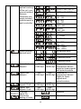
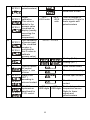
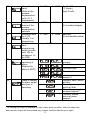
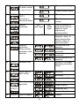
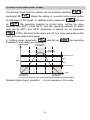
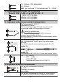
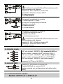
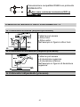
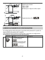
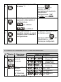
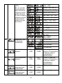
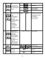
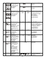
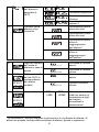
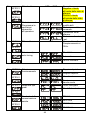
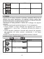
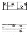
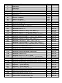
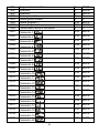
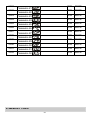
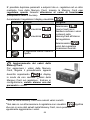
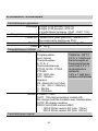
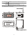
REGOLATORE
CONTROLLER
ATR121
ATR141
Manuale
User Manual
Contents
1 SECTION FOR USERS.................................................................................................... 4
2 DISPLAYS AND KEYS ..................................................................................................... 4
3 CHANGE OF SETPOINT VALUE..................................................................................... 5
4 LIST OF ERROR MESSAGES ......................................................................................... 5
5 SECTION FOR INSTALLERS .......................................................................................... 6
6 INTRODUCTION .............................................................................................................. 6
7 ORDERING CODES......................................................................................................... 6
8 TECHNICAL DATA........................................................................................................... 7
8.1 Sizes and installation ............................................................................................... 8
9 ELECTRICAL WIRINGS................................................................................................... 9
10 WIRING DIAGRAM ATR121 / ATR141 ........................................................................ 9
10.1 Low tension power supply 12/24 Vac-Vdc Models: ATR121-AD , ATR141-AD .... 9
10.2 Power supply 24/115/230 Vac Models: ATR121-A-B-C , ATR141-A-B-C............. 9
10.3 Analog input for temperature sensors.................................................................. 10
10.4 Analog input V / mA ............................................................................................. 10
10.5 Relay outputs ....................................................................................................... 11
10.6 SSR output........................................................................................................... 11
10.7 Serial communication Models ATR121-xT , ATR141-xT...................................... 11
11 OPERATING MODE OF ALARM OUTPUT OUT2 ....................................................... 12
11.1 Band alarm (setpoint-process)............................................................................. 12
11.2 Deviation alarm (setpoint-process) ...................................................................... 12
11.3 Absolute alarm (process)..................................................................................... 12
12 MODIFY CONFIGURATION PARAMETERS ............................................................... 13
13 CONFIGURATION PARAMETERS.............................................................................. 14
14 TUNING........................................................................................................................ 19
15 MANUAL START OF TUNING ..................................................................................... 19
16 AUTOTUNING.............................................................................................................. 20
17 FUNCTION LATCH ON................................................................................................ 21
18 FUNCTION NEUTRAL ZONE ...................................................................................... 23
19 SERIAL COMMUNICATION......................................................................................... 24
20 MEMORY CARD .......................................................................................................... 28
21 SUPERVISORY SYSTEM WITH CONTROLLERS ATR121 / 141............................... 29
22 CONFIGURATION MEMORANDUM............................................................................ 31
23 NOTES / UPDATE........................................................................................................ 32
24 SEZIONE UTENTE ..................................................................................................... 33
25 VISUALIZZATORI E TASTI.......................................................................................... 33
2
26 CAMBIO DEL SETPOINT ............................................................................................ 34
27 SEGNALAZIONE ANOMALIE ...................................................................................... 34
28 SEZIONE INSTALLATORE......................................................................................... 35
29 INTRODUZIONE .......................................................................................................... 35
30 COMPOSIZIONE DELLA SIGLA.................................................................................. 35
31 CARATTERISTICHE .................................................................................................... 36
31.1 Dimensioni e installazione ................................................................................... 37
32 COLLEGAMENTI ELETTRICI ...................................................................................... 38
33 SCHEMA DI COLLEGAMENTO ATR121 / ATR141................................................... 38
33.1 Alimentazione in bassa tensione 12/24 Vac-dc Modelli: ATR121-AD e ATR141-AD
.................................................................................................................................. 38
33.2 Alimentazione da rete a 24/115/230 Vac Modelli: ATR121-AB o C e ATR141-AB o
C ............................................................................................................................... 39
33.3 Ingresso analogico per sonde in temperatura ..................................................... 39
33.4 Ingresso analogico normalizzato ......................................................................... 39
33.5 Uscite a relè......................................................................................................... 40
33.6 Uscita SSR........................................................................................................... 40
33.7 Comunicazione seriale Modelli: ATR121-xT e ATR141-xT.................................. 40
34 MODI DI INTERVENTO USCITA ALLARME OUT 2 .................................................... 41
34.1 Intervento di banda (setpoint-processo) .............................................................. 41
34.2 Intervento di deviazione (setpoint-processo) ....................................................... 41
34.3 Intervento indipendente (processo) ..................................................................... 41
35 MODIFICA PARAMETRI DI CONFIGURAZIONE ........................................................ 42
36 TABELLA PARAMETRI DI CONFIGURAZIONE .......................................................... 43
37 TUNING........................................................................................................................ 49
38 LANCIO DEL TUNING MANUALE ............................................................................... 49
39 TECNICA DI TUNING AUTOMATICO.......................................................................... 50
40 FUNZIONE LATCH ON ................................................................................................ 51
41 FUNZIONE BANDA MORTA ........................................................................................ 52
42 COMUNICAZIONE SERIALE....................................................................................... 53
43 MEMORY CARD .......................................................................................................... 57
44 SUPERVISIONE CON ATR121 / 141 .......................................................................... 59
45 PROMEMORIA CONFIGURAZIONE ........................................................................... 60
46 NOTE / AGGIORNAMENTI .......................................................................................... 61
47 IDENTIFICATION DU MODELE................................................................................... 62
48 DONNEES TECHNIQUES ........................................................................................... 63
48.1 Dimensions et installation .................................................................................... 64
49 RACCORDS ÉLECTRIQUES....................................................................................... 65
3
1 SECTION
FOR USERS
2 DISPLAYS
AND KEYS
Display normally shows
process value (ex. measured temperature),
but can also visualize setpoints or value of
entering data
ATR121
Visualize set, increase set
or scroll parameters
(whith fast advancement)
OUT 1
OUT 2
L1
FNC
SET
Visualize set, decrease set,
scroll parameters.
(whith fast advancement)
PIXSYS
Visualize setpoints (ex. programmed temperature):
press once for SET1 (Led Out1 flashes),
press twice for SET2 (Led Out2 flashes).
In configuration mode press with arrow
keys to modify value of visualized parameter.
Fleshing when setpoint is visualized
on display and can be modified.
ON when output is active.
ATR141
OUT 1
OUT 2
L1
FNC
ON when controller responds
to a Master request over
serial line RS485
SET
PIXSYS
Enter configuration of parameters (by password).
Activate special functions.
4
3 CHANGE
OF SETPOINT VALUE
To modify the setpoint value, press SET key or one of the arrow-keys: led
OUT1 flashes and it is now possible to enter/modify setpoint value by
pressing the arrow-keys.
Press
1
Display
or
or
SET
Do
Display shows main
setpoint; Led
Press
or
OUT1 flashes.
To modify setpoint (fast
advancement available).
Approx. 4 seconds after last
modify, display shows again
process value (value read by
sensor input).
2
4 LIST
SET
Display shows
alarm setpoint and
Press
or
to
led OUT2 flashes.
increase or decrease setpoint
value.
When the keys are released,
the new value is automatically
stored and in a few seconds
display shows again process
value.
OF ERROR MESSAGES
If the plant does not work properly, the controller stops the running cycle
and shows the anomaly.
For example the controller will notice the failure of a thermocouple
displaying
(flashing).
For further error signs check the list below.
Error
Cause
Programming error EPROM.
Cold junction failure or room
temperature out of range
Wrong
configuration
data.
Possible lost of calibration values
5
Do
Check configuration
parameters
Open thermocouple or
temperature out of range
5 SECTION
room Check sensors connection
and their integrity
FOR INSTALLERS
6 INTRODUCTION
Thanks for choosing a Pixsys Controllers.
Various models with 3-4 digits display make the controller suitable for a
wide range of applications with temperature, humidity, pressure sensors
and linear potentiometers. Output options include both relays and SSR,
but the unit is configurable also as visualizer/indicator for applications not
requiring control or alarm outputs. PID control with Autotuning function
enables to adapt control algorithm to the plant. For applications with linear
potentiometers the function LATCH ON allows a quick calibration.
Memory-card is available to copy configuration parameters and to keep
record of them.
The tables below allow to select easily the required model.
7 ORDERING
CODES
Ordering codes model ATR121
ATR121xx
x
12…24Vac ± 10% 50/60Hz
Power supply AD
A
B
C
Serial A
communication AD
12…35Vdc
24 Vac ± 10% 50/60 Hz
230 Vac ± 10% 50/60 Hz
115 Vac ± 10% 50/60 Hz
T RS485 - protocoll Modbus RTU slave.
T Relay Q2 +alarm function not available in this
model
Only Code AT: 24Vac +/- 10% 50/60 Hz
Only Code ADT: 12…35Vdc
Ordering codes Model ATR141
ATR141xx
x
12…24Vac ± 10% 50/60Hz
Power supply AD
A
B
C
12…35Vdc
24 Vac ± 10% 50/60 Hz
230 Vac ± 10% 50/60 Hz
115 Vac ± 10% 50/60 Hz
6
Serial A
communication AD
8 TECHNICAL
T RS485 -protocol Modbus RTU slave.
T Relay Q2 +alarm function not available in this
model
Only Code AT: 24Vac +/- 10% 50/60 Hz
Only Code ADT: 12…35Vdc
DATA
Main features
Displays 3 digits (0,56 inches) on ATR121
4 digits (0,40 inches) on ATR141
+ 3 Leds (Out1 , Out2 , Fnc)
Operating temperature 0-40°C - humidity 35..95uR%
Sealing Front panel IP65 (with gasket) /
Box IP30 / Terminal blocks IP20
Material ABS UL94V2 self- exstinguish
Weight Approx. 100 gr.
Hardware data
Analog input AN1
Software configurable
Tolerance 25°C
Thermocouples K, J, S, R 0.5 % ± 1 digit for
PT100, NI100, PT500,
thermocouples and
PT1000, PTC 1000 ohm , RTD
NTC 10Kohm
Cold junction
0/4..20mA (Ri<=4,7ohm) 0.2°c/°c of ambient
0...10V(Ri>=110Kohm)
temperature
0…6Kohm
0.2% ± 1 digit for V,
0…150Kohm
mA
Outputs 2 Relays + SSR:
OUT1 :10A resistive on AD codes,
8A resistive with internal transformer
OUT2 : 5A resistive
SSR : 8 Volt 20mA for version A/B/C
15 Volt 30mA for version AD (alim. 12Vac)
30 Volt 30mA for version AD (alim. 24Vac)
Software data
Control algorithm On/OFF with hysteresis or P.I.D. with Autotuning
Data protection
Configuration password, quick programming by
Memory card
7
8.1 Sizes
and installation
ATR121
OUT 1
OUT 2
L1
FNC
SET
PIXSYS
8
9 ELECTRICAL
WIRINGS
Although this controller has been designed to resist the noises in
an industrial environment, please notice the following safety
guidelines:
• Separate control lines from the power wires.
• Avoid the proximity of remote control switches, electromagnetic
meters, powerful engines.
• Avoid the proximity of power groups, especially those with
phase control
10 WIRING
DIAGRAM ATR121 / ATR141
PIXSYS
M065486-0604
ATR121-AD
2 wire
PIXSYS
M065486-0604
ATR141-B
4/20mA
2 wire
Power
1
1
2
10A 230V
Cosf 1
5A 230V
Cosf 1
3A 230V
Cosf 0.8
1A 230V
Cosf 0.8
Q1
Q2
3
4
5
6
8A 230V
Cosf 1
5A 230V
Cosf 1
3A 230V
Cosf 0.8
1A 230V
Cosf 0.8
Q1
Q2
PT/NI100/1K
PTC/NTC
7
8
9
10
11
12
1
Memory
1
PIXSYS
M065486-0604
2
3
4
5
6
PT/NI100/1K
PTC/NTC
7
8
9
10
Memory
ATR121-AT
2 wire
4/20mA
Power
8A 230V
Cosf 1
PT/NI100/1K
3A 230V
Cosf 0.8
Q1
1
1
2
3
4/20mA
Power
4
PTC/NTC
RS485
5
6
7
8
9
10
11
12
Memory
10.1 Low
tension power supply 12/24 Vac-Vdc
Models: ATR121-AD , ATR141-AD
12…24Vac ± 10% 50/60Hz
12…35Vdc
**Code “T” with serial communication ONLY
12…35Vdc
10.2 Power
supply 24/115/230 Vac
Models: ATR121-A-B-C , ATR141-A-B-C
9
11
12
24Vac ± 10% 50/60Hz
230Vac ± 10% 50/60Hz
115Vac ± 10% 50/60Hz
10.3 Analog
input for temperature sensors
Thermocouples K, S, R;J;
Respect polarities
When extending thermocouples be sure to use the
correct extension/compensating cable
Pt 100 3 Wires
Only model AD
To assure optimal operation of the device, use
ground-isolated sensors.
Otherwise use single isolated transformers for
each controller
For a three-wires PT100 use cables with the same
diameter;
For a two-wires Pt100 shortcircuit pins 10 and 12.
3
2
1
For
10.4 Analog
PTC 1000 ohm
NTC 10 K
PT500, PT1000
Linear potentiometers 6K or 150K
input V / mA
Signals
0…10V
Respect polarities
Ri>=110KΩ
Signals
0 ÷ 20mA or 4 ÷ 20mA
with three-wires sensors
Respect polarities
A= sensor supply
Check power supply requirements on technical
data sheet of sensor!
Capacity 12…24V / 30mA for models AD
10
Capacity 8V / 20mA for models A-B-C
B= sensor ground
C= sensor output
Signals
0 ÷ 20mA or 4 ÷ 20mA
with sensors requiring external power supply
Respect polarities
B= sensor ground
C= sensor output
Signals
4 ÷ 20mA with two-wires sensors
Respect polarities
A= sensor supply
Check power supply requirements on technical
data sheet of sensor!
Capacity 12…24V / 30mA for models AD
Capacity 8V / 20mA for models A-B-C
C= sensor output
10.5 Relay
outputs
• Q1 capacity 8A/250V~ (Models A-B-C) resistive
(manoeuvre 2x10⁵min - 8A/250V~)
• Q1 capacity 10A/250V~ (Model AD) resistive
(manoeuvre 2x10⁵min -10A /250V~)
• Q2 capacity 5A/250V~ resistive (manoeuvre
2x10⁵min a 3A /250V~)
10.6 SSR
output
Capacity 12…24V/30mA on model AD
Capacity 8V/20mA on models A-B-C
Command output if configured as SSR
10.7 Serial
communication
Models ATR121-xT , ATR141-xT
RS485, protocol MODBUS-RTU
11
Do not use LT (line termination) resistors
11 OPERATING
11.1 Band
MODE OF ALARM OUTPUT OUT2
alarm (setpoint-process)
Comparison value
Hysteresis
Operating mode:
• active outside band
• active inside band
Example : outside
Hysteresis
Time
11.2 Deviation
alarm (setpoint-process)
Comparison value
Operating mode:
• deviation high
• deviation low
Example: deviation high.
Hysteresis
Time
11.3 Absolute
alarm (process)
12
Comparison value
Hysteresis
Operating mode:
•
active over
•
active below
Example: active below
Time
Comparison value
Hysteresis
Programming Par.
Delay
Positive
Delay
Negative
12 MODIFY
CONFIGURATION PARAMETERS
The configuration menu of the unit is password protected to prevent
unauthorised access to the instrument set up.
Press
1
FNC
Display
After 5 seconds display
Do
shows
, first digit on
the left is flashing.
on ATR141
Increase first digit to “1”.
2
SET
Press
to reach
following digit and enter
configuration password
“123” for ATR121
or “1234” for ATR141
13
3
SET
Display shows first
configuration parameter
for ATR121
for ATR141
The arrow-keys allow the
movement through the
configuration table in both
forward and backward
directions.
4
13
P
Display
Description
ATR121
Select type of
control output
ATR141
2
SET
to
modify, press
visualize it and use arrow
keys to modify value.
CONFIGURATION PARAMETERS
ATR121
1
Select parameter to
Select type of
connected
sensor
Range
ATR141
Description
Control Q1
Alarm Q2
Control Q1
Alarm SSR
Control SSR
Alarm Q1
TC type K
-260…1360
TC type S
-40…1760
TC type R
-40…1760
only for
AD models :
TC type J
-200…1200
14
To assure
optimal working
of the unit, use
ground-isolated
sensors.
Otherwise use
single isolated
transformers for
each controller.
Pt100 (-100..600°C)
Pt100 (-100..140°C)
Ni100 (-60..180°C)
Ntc 10KΩ
-40…125
Ptc 1KΩ
-50…150
Pt500
-100…600
Pt1000
-100…600
0…10V
0…20mA
4…20mA
Pot. 6KΩ
Max 6KΩ
Pot. 150KΩ
Max 150KΩ
3
Select position
decimal point
no decimal point
1 decimal point
2 decimal points
-----------
4
Lower limit
setpoint
-199..
+999 digit
5
Upper limit
setpoint
-199…
+999 digit
6
Lower limit
signals V/mA
Upper limit
signals V/mA
Function
Latch On
(Automatic
setting of limits
-199…
+999 digit
-199…
+999 digit
7
8
ATR121
3 decimal points
-999..
Degrees for
+9999 digit temperature sensor
digits for linear signals
and potentiometers
-999…
Degrees for
+9999 digit temperature sensor.
Digits for linear
signals and
potentiometers
-999…
+9999 digit
-999…
+9999 digit
disabled
Standard
15
ATR141
for linear
potentiometers)
virtual zero stored
virtual zero at start
9
ATR121
ATR141
10
ATR121
ATR141
11
Offset
calibration.
This value is
added to the
process value
visualized on
display (usually
correcting the
ambient
temperature)
Gain calibration
of sensor input
(The visualized
number is
multiplied for
this % value to
calibrate
process value)
Type of control
-19.9…
+99.9 units
-99.9…
+99.9
units
Tenth of degree for
temperature. Digits for
linear signals and
potentiometers
-10.0%…+10.0%
Heating (N.O.)
Cooling (N.C.)
12
13
ATR121
ATR141
14
ATR121
ATR141
Type of contact
for control
output in case
of error
State of led
OUT1
according to
relevant contact
ON/OFF
hysteresis or
dead band for
P.I.D. control
Open contact safety
Closed contact safety
On with open contact
On with closed
contact
-199…
-999…
Tenth of degree for
+999 digits +999 digits temperature sensor.
Digits for linear
signals and
potentiometers
16
15
16
17
18
19
Proportional
band
Width of the
process
expressed as
units (°C if
temperature)
Integral time.
Inertia of the
process
expressed as
seconds
Derivative time
for P.I.D.
Usually ¼ of
integral time
Cycle time for
timeproportioning
output (usually
over 10s for
contactors, 1s
for SSR)
Select
operating of
alarm.
Setpoint for
alarm is SET2.
0…999
0…9999
0-999
0-9999
0…999
0…9999
1-300
0 = On/Off
°C (temp.)
digit (V/mA)
seconds
(0 excludes Integral)
seconds
(0 excludesDerivative)
seconds
absolute related to
process
band alarm
Deviation high
Deviation low
20
absolute related to
setpoint 1
Normally open, active
at Start
Normally closed,
active at Start
Normally open, active
1
at alarm setpoint .
Normally closed,
active at alarm
1
setpoint
State of contact
for alarm output
and type of
operating
1
At starting the output is desabled in case of any alarm condition. After the alarm has
been solved, output will be activated only if alarm condition should occur again.
17
21
22
ATR121
ATR141
23
ATR121
State of contact
for alarm output
in case of error
Open contact safety
State of led
OUT2
according to
relevant contact
ON with open contact
Alarms
hysteresis
Closed contact safety
ON with closed
contact
-199…
+999 digits
ATR141
24
ATR121
Alarm delay
-180…+180
ATR141
25
26
Setpoint
protection.
Select options
available to the
operator
ATR121
Software filter
1-15
ATR141
27
ATR121
Select type of
auto-tuning
ATR121
Tenth of degree for
temperature sensor.
Digits for linear
signals and
potentiometers
seconds
Negative: delay at
alarm deactivation
Positive: delay at
alarm activation
Access free to all
setpoints
Control setpoint
protected
Alarm setpoint
protected
Access denied to all
setpoints
Number of averages
(Sampling frequency
15Hz)
desabled
automatic
ATR141
28
-999…
+9999
digits
manual start of Tuning
Select type of
operating
Double setpoint
Single setpoint
Visualizer only
ATR141
function Neutral zone
29
ATR121
Type of degree
Celsius
18
Fahrenheit
ATR141
30
ATR121
Baud rate of
serial
communication
300 bit/s
9600 bit/s
19200 bit/s
ATR141
38400 bit/s
31
ATR121
Slave address
1-254
Delay serial
communication
0-100
ATR141
32
ATR121
Milliseconds
ATR141
14 TUNING
Tuning operation allows the setting of optimal PID parameters in order to
assure good control action:
-Stable, “straight-line” control of temperature around setpoint, without
fluctuations;
-quick response to deviations from setpoint caused by external noises
Tuning involves calculating and setting of the following parameters:
• Proportional band (inertia of plant; expressed as °C for temperature)
• Integral time (determines the time taken by the controller to remove
steady-state error signals, Inertia of plant expresses as time value);
• Derivative time (reaction of controller to change of measured value,
usually ¼ of integral time)
Setpoint value cannot be modified during Autotuning.
15 MANUAL
START OF TUNING
Select parameter
Press
as
(manual start)
Display
Do
19
1
FNC
Display shows
Display shows
2
Display will show process
3
FNC
or
wait for 4
seconds.
To interrupt the function
value and
FNC
alternately until the function press
and press
is completed (it may take a
few minutes).
to select
.
16 AUTOTUNING
Parameter
must be selected as
. Autotuning starts
automatically when the controller is switched-on or when setpoint value
20
has been modified. Display alternates between process value and the
writing
minutes).
until the function has been completed (it may take a few
To interrupt the function, press
17 FUNCTION
FNC
and press
.
LATCH ON
For application with linear potentiometers
6K) and
to select
(potentiometer up to
(potentiometer up to 150K) or 0…10Volt , 0/4…20mA
) can be set to
inputs, the lower limit of scale (see parameter
minimum position of sensor; it is also possible to set the upper limit of
scale (parameter
be done directly on site.
) to the max. position of sensor and this can
The option “virtual zero” (selecting
or
) allows also to fix
the point where the controller will read zero (but still keeping the range of
and
scale between
Selecting
.
virtual zero must be reprogrammed at each starting of
the controller; selecting
virtual zero will be stored after first
calibration.
To enable function LATCH ON, select chosen configuration for parameter
2
. For calibration function follow the table below.
Press
Display
Do
2
Calibration function leaves configuration mode after that the relevant
parameter has been modified.
21
1
FNC
2
Leave configuration mode.
Set the sensor on minimum
Display shows cycling process operating value
value and writing
Store minimum value.
.
Display shows
FNC
Display shows
press
.
To enter “virtual zero” set the
sensor to zero point.
To interrupt the function
Store virtual zero.
4
SET
)
(corresponding to
)
To quit standard proceeding
Store max. value
3
(corresponding to
Set the sensor on max.
operating value
Display shows
is selected, at
** If
starting repeat calibration on
point 4.
press
FNC
.
MAX
MIN
22
ZERO
18 FUNCTION
NEUTRAL ZONE
The Neutral Zone function (which can be enabled selecting
parameter 28
on
) allows the setting of a neutral zone control action
as described in the graph. In Heating mode (parameter
selected
), the operating treshold for control relay will be the value
as
resulting from SET1 minus SET2, and the operating treshold for alarm
relay will be SET1 plus SET2 (hysteresis is always set via parameter
). Within this band both relays are off; one relay works above this
band and one relay works below.
In Cooling mode (parameter
selected as
tresholds of both relays are reversed.
TEMPERATURE
) the operating
Operating Zone
alarm Relay
PROCESS
Hysteresis (HY.C)
SET 2
SET 1
SET 2
Hysteresis (HY.C)
TIME
Operating Zone
comand Relay
Operating Zone
Comand Relay
Ex. Function neutral zone for heating modality (HEA/HEAT on parameter REG)
Standard alarm (band, deviation …) is not available in this mode.
23
19 SERIAL
COMMUNICATION
Serial communication RS485 and protocol MODBUS – RTU enable the
controller ATR121/141 to receive and exchange data, allowing the
connection of more units to a centralized supervisory system. The device
can be configured only as Slave unit.
LT (line termination) resistors on RS485 line must be removed to avoid
anomalies.
Each controller will respond to a request only if it contains the same
. The range of admitted
address which is written on parameter
addresses is 1 – 254. Address 255 is used to communicate with all the
connected units (Broadcast modality). Single units ATR121/141 on the
same line cannot have the same address. Selecting 0 all connected units
receive request but no answer is required. ATR121/141 may delay the
answer to request. This delay (expressed as milliseconds) must be
entered on parameter
After each parameters change, the controller stores the new values on
EEPROM memory ( 100000 writing). Modified sepoint values are stored
on EEPROM memory with 10 seconds delay.
** Any operation on words which are not listed in the table below may
cause anomalies or malfunction.
Baud-rate
Selectable by parameter
MD.1 = 300bit/s
MD.2 = 9600bit/s
MD.3 = 19200bit/s
MD.4 = 38400bit/s
Format 8, N, 1 (8bit, no parity, 1 stop)
Supported functions WORD READING (max 20 word)
SINGLE WORD WRITING
MULTIPLE WORDS WRITING
24
(0x03, 0x04)
(0x06)
(0x10)
MODBUS
ADDRESS
0
1
2
3
4
5
6
60
61
62
63
64
65
300
301
302
303
304
305
306
307
308
309
310
311
312
313
314
315
316
317
318
DESCRIPTION
Type of device
Software version
Reserved
Reserved
Reserved
Slave Address
Reserved
Type of calibration
Calibration action
Calibration value
Calibration Password
Calibration completed
State of relays during calibration
Calibration 0mV TC
Calibration 40mV TC
Calibration 100Ω PT100 (-100..600°C)
Calibration 300Ω PT100 (-100..600°C)
Calibration 100Ω comp. PT100 (-100..600°C)
Calibration 300Ω comp. PT100 (-100..600°C)
Calibration 100Ω PT100 (-100..140°C)
Calibration 138.5Ω PT100 (-100..140°C)
Calibration 100Ω comp. PT100 (-100..140°C)
Calibration 138.5Ω comp. PT100(100..140°C)
Calibration 0V sensor 0-10V
Calibration 10V sensor 0-10V
Calibration 0mA sensor 0/4-20mA
Calibration 20mA sensor 0/4-20mA
Calibration 10KΩ NTC
Calibration 1KΩ PTC or PT1000
Calibration ambient temperature (OFFSET)
Calibration ambient temperature (mV diode L)
Calibration ambient temperature (mV diode H)
25
READ/
WRITE
RESET
VALUE
R
R
R
R
R
R
R
R/W
R/W
R/W
R/W
R
R/W
R
R
R
R
R
R
R
R
R
R
101/102
?
?
?
0
EEPR
?
0
0
0
0
EEPR
0
EEPR
EEPR
EEPR
EEPR
EEPR
EEPR
EEPR
EEPR
EEPR
EEPR
R
R
R
R
R
R
R
R
R
EEPR
EEPR
EEPR
EEPR
EEPR
EEPR
EEPR
EEPR
EEPR
319
400
401
402
403
404
405
406
407
408
409
1000
1001
1002
1003
1004
2001
2002
2003
2004
2005
2006
2007
2008
2009
2010
2011
2012
2013
2014
2015
Calibrations Flags completed
Setpoint 1
Setpoint 2
Lower value Latch-on H
Lower value Latch-on L
Upper value Latch-on H
Upper value Latch-on L
Value Virtual zero Latch-on
Control Flags Latch-on
Reserved
Reserved
Process value
Cold junction value
Value Setpoint 1
Value Setpoint 2
Percentage control output
Parameter 1
Parameter 2
Parameter 3
Parameter 4
Parameter 5
Parameter 6
Parameter 7
Parameter 8
Parameter 9
Parameter 10
Parameter 11
Parameter 12
Parameter 13
Parameter 14
Parameter 15
26
R
R
R
R
R
R
R
R
R
R
R
R
R
R/W
R/W
R
R/W
EEPR
EEPR
EEPR
EEPR
EEPR
EEPR
EEPR
EEPR
EEPR
EEPR
EEPR
0
0
EEPR
EEPR
0
EEPR
R/W
EEPR
R/W
EEPR
R/W
EEPR
R/W
EEPR
R/W
EEPR
R/W
EEPR
R/W
EEPR
R/W
EEPR
R/W
EEPR
R/W
EEPR
R/W
EEPR
R/W
EEPR
R/W
EEPR
R/W
EEPR
2016
2017
2018
2019
2020
2021
2022
2023
2024
2025
2026
2027
2028
2029
2030
2031
2032
Parameter 16
Parameter 17
Parameter 18
Parameter 19
Parameter 20
Parameter 21
Parameter 22
Parameter 23
Parameter 24
Parameter 25
Parameter 26
Parameter 27
Parameter 28
Parameter 29
Parameter 30
Parameter 31
Parameter 32
27
R/W
EEPR
R/W
EEPR
R/W
EEPR
R/W
EEPR
R/W
EEPR
R/W
EEPR
R/W
EEPR
R/W
EEPR
R/W
EEPR
R/W
EEPR
R/W
EEPR
R/W
EEPR
R/W
EEPR
R/W
EEPR
R/W
EEPR
R/W
EEPR
R/W
EEPR
20 MEMORY
CARD
Parameters and setpoint values can be easily copied from one controller
to others using the MEMORY CARD. The controller must be switchedoff before entering the Card. Check also entry direction (components
must be turned towards front panel).
3
.
Switching-on the controller, display will show
Press
Display
Do
1
2
FNC
shows
,
shows
.
Select
(Memo
load) to store values of
Memory on the controller.
Select
to keep
values of the controller
unchanged.
The controller stores value
and restarts.
Updating values of memory card
To update values of Memory card follow
the above proceedings, selecting
on display, so values of memory will not
4
be stored on the controller . Enter
configuration mode, modify at least one
parameter and exit.
3
Only if values stored on Memory Card are correct.
4
If the controller does not visualize
at starting, this means that no
values are stored on Memory Card, but they may be copied and updated.
28
21 SUPERVISORY
SYSTEM WITH CONTROLLERS ATR121 / 141
Below main elements of the system. Consider the converter
RS232/RS485 with automatic direction and the suggested serial
communication cables.
29
12
11
10
RS485
Controller SLAVE
Mod. : ATR121-AT
1
Controller SLAVE
Mod. : ATR121-AT
6
7
8
9
PTC/NTC
PT/NI100/1K
12
11
10
RS485
6
7
8
9
PTC/NTC
PT/NI100/1K
12
11
10
RS485
6
7
8
9
PTC/NTC
PT/NI100/1K
Sensor : PT100
2
Controller SLAVE
Mod. : ATR121-AT
254
PERSONAL COMPUTER
Serial line
RS 485
Serial line
RS 232
Converter Rs232 / Rs485
Automatic direction
Mod. : PIX-RECORDER
Use shielded cable
1 twisted pair.
According to EIA RS-485.
Suggested cable: Belden 9841.
AN-0020-3704
30
22 CONFIGURATION
MEMORANDUM
Date:
Installer:
Notes:
Par.
Model ATR121/141:
Plant:
Description
Select type of command output
Sensor Type
Default
Visualization of decimal point
Lower limit of setpoint
Upper limit of setpoint
ATR121
ATR141
Lower limit only for V/I V/mA
Upper limit only for V/I V/mA
Latch On Function
Offset calibration
Gain calibration
Type of action
Type of contact for control output in
case of anomaly
Select state of OUT1
Hysteresis dead/band
Proportional band
Integral time
Derivative time
Proportional cycle time
Type of alarm
Contact alarm OUT
State of contact for alarm output in case
of anomaly
State of the LED
Alarms hysteresis
31
0
999
1750
0
999
0.0
0
0
0
0
0
10
0
Prom.
delay alarm
Set protection.
0
Software filter
Type of autotuning
10
Type of operating
Degrees selection
Baud rate
address slave
Serial delay
23 NOTES
254
20
/ UPDATE
32
24 SEZIONE
UTENTE
25 VISUALIZZATORI
E TASTI
Visualizza normalmente
il processo (es.: Temperatura sonda),
ma può visualizzare anche il valore
dei setpoint (punti d’intervento)
oppure i dati in inserimento.
ATR121
Visualizza il set, incrementa
il set o scorre i parametri
(con avanzamento veloce).
OUT 1
OUT 2
L1
FNC
SET
Visualizza il set, decrementa
il set o scorre i parametri.
(Con avanzamento veloce)
PIXSYS
Visualizza i setpoint (ex.:temperatura impostata):
una pressione Set1(Led Out1 lampeggia) ,
seconda pressione Set2 (Led Out2 Lampeggia).
In Configurazione se premuto contemporaneamente
ad uno dei tasti freccia permette di
modificare il valore del parametro visualizzato.
Quando lampeggiano stanno ad indicare il setpoint visualizzato
sul display e quindi la possibilità di variarlo con i tasti freccia.
Quando accesi fissi indicano l’uscita attiva.
ATR141
OUT 1
OUT 2
L1
FNC
Si accende quando il regolatore
risponde ad un’interrogazione da
Seriale (versione con RS485).
SET
PIXSYS
Accesso alla programmazione dei parametri(sotto password).
Attiva le funzioni speciali
33
26 CAMBIO
DEL SETPOINT
SET
Per modificare il valore impostato premere il tasto
una volta, o
premere uno dei tasti freccia; il led OUT1 lampeggia, è quindi possibile
impostare un nuovo valore con le frecce.
Premere Effetto
Eseguire
1
oppure
Il display
visualizza il
setpoint di
comando e il Led
OUT1 lampeggia.
oppure
Premere uno dei tasti
,
per modificare il valore di setpoint (con
avanzamento veloce). Dopo circa 4
secondi dall’ultima modifica il display torna
a visualizzare il processo (ingresso sonda).
SET
2
SET
Il display
visualizza il
setpoint di
allarme e il Led
OUT2 lampeggia.
27 SEGNALAZIONE
Premere
o
per aumentare o
diminuire il valore di setpoint desiderato.
Al rilascio dei tasti dopo circa 4 secondi il
nuovo valore viene registrato
automaticamente, il display torna a
visualizzare il processo
ANOMALIE
In caso di mal funzionamento dell’impianto, il regolatore attiva i relè, come
da parametri 12 e 21 e segnala il tipo di anomalia riscontrata. Per
esempio il regolatore segnalerà la rottura di una eventuale termocoppia
collegata visualizzando
(lampeggiante) sul display.
Per le segnalazioni vedere la tabella:
Errore Causa
Cosa Fare
Errore in programmazione cella EPROM.
Guasto sensore temperatura giunto
freddo o temperatura ambiente al di
fuori dei limiti ammessi.
Dati di configurazione errati. Possibile
perdita della tarature dello strumento.
34
-
Verificare che i parametri di
configurazione siano corretti.
Termocoppia aperta o temperatura
fuori limite.
28 SEZIONE
Controllare il collegamento
con le sonde e la loro
integrità.
INSTALLATORE
29 INTRODUZIONE
Grazie per aver scelto un regolatore Pixsys.
Le versioni con display a tre e quattro digits permettono di impiegare lo strumento
in una vasta gamma di applicazioni, ad esempio con sensori di temperatura,
umidità, pressione, livello o potenziometri lineari. Le soluzioni di uscita prevedono
sia il relè che la logica per SSR, è comunque configurabile il solo funzionamento
come visualizzatore per gli impianti che non necessitano di uscite comando o di
allarme. Con il PID e l’Autotune è semplice adattare all’impianto l’algoritmo di
regolazione migliore, mentre nel caso di funzionamento con potenziometri lineari
la funzione LATCH ON velocizza la taratura della macchina.
Come sulla più recente strumentazione Pixsys sono disponibili Memory-card per
la configurazione in serie e per lo storico degli impianti.
Seguendo le tabelle sottostante si può facilmente identificare il modello
desiderato.
30 COMPOSIZIONE
DELLA SIGLA
Composizione della sigla Modello ATR121
ATR121xx x
12…24Vac ±10% 50/60Hz
Alimentazione AD
A
B
C
Seriale A
AD
T
T
12…35Vdc
24 Vac ±10% 50/60 Hz
230 Vac ±10% 50/60 Hz
115 Vac ±10% 50/60 Hz
Rs485 con protocollo Modbus RTU slave.
In questa versione non è disponibile il Relè Q2 e la
funzione allarme è inibita.
Solo versione AT: 24Vac ±10% 50/60 Hz
Solo versione ADT: 12…35Vdc
Composizione della sigla Modello ATR141
ATR141xx x
12…24Vac ±10% 50/60Hz
Alimentazione AD
A
B
C
12…35Vdc
24 Vac ±10% 50/60 Hz
230 Vac ±10% 50/60 Hz
115 Vac ±10% 50/60 Hz
35
Seriale A
AD
T
T
Rs485 con protocollo Modbus RTU slave.
In questa versione non è disponibile il Relè Q2 e la
funzione allarme è inibita.
Solo versione AT: 24Vac ±10% 50/60 Hz
Solo versione ADT: 12…35Vdc
31 CARATTERISTICHE
Caratteristiche generali
Display 3 display (0,56 pollici) su ATR121
4 display (0,40 pollici) su ATR141
+ 3 led (Out1 , Out2 , Fnc)
Temperatura di esercizio 0-40°C - umidità 35..95uR%
Protezione Pannello frontale IP65 (con guarnizione) /
Contenitore IP30 / Morsettiere IP20
Materiale Policarbonato UL94V0 autoestinguente
Peso ca. 100 g.
Caratteristiche hardware
Ingressi analogici AN1
configurabile via software Tolleranze a 25°C
Termocoppie : K, S, R, J 0.5 % ± 1 digit x
Termoresistenze: PT100, termocoppie e
termoresistenze
NI100, PT500, PT1000,
Giunto freddo
PTC 1000 ohm ,
0.2°c/°c di
NTC 10Kohm
temperatura
Segnali:
0/4..20mA (Ri<=4,7ohm) ambiente
0...10V (Ri>=110Kohm) 0.2% ± 1 digit per
V/I
0…6Kohm
0…150Kohm
Uscite 2 Rele’ + SSR:
OUT1: 10A carico resistivo su versione AD , 8A
carico resistivo su versioni con trasformatore.
OUT2: 5A carico resistivo.
SSR:8 Volt 20mA per versioni A/B/C.
15Volt 30mA per versioni AD(alim. 12Vac)
30Volt 30mA per versioni AD(alim. 24Vac)
Caratteristiche software
Algoritmo di On/OFF con isteresi o P.I.D. con Autotune
regolazione
36
Protezione dati Parametri sotto password programmazione veloce da
memory-card
31.1 Dimensioni
e installazione
ATR121
OUT 1
OUT 2
L1
FNC
SET
PIXSYS
37
32 COLLEGAMENTI
ELETTRICI
Benché questo regolatore sia stato progettato per resistere ai più
gravosi disturbi presenti in ambienti industriali, è buona norma
seguire le seguenti precauzioni:
Distinguere la linea d’alimentazione da quelle di potenza.
Evitare la vicinanza di gruppi di teleruttori, contattori
elettromagnetici, motori di grossa potenza.
Evitare la vicinanza di gruppi di potenza, in particolare se a
controllo di fase.
33 SCHEMA
DI COLLEGAMENTO ATR121 / ATR141
PIXSYS
M065486-0604
ATR121-AD
2 wire
PIXSYS
M065486-0604
ATR141-B
4/20mA
2 wire
Power
1
1
2
10A 230V
Cosf 1
5A 230V
Cosf 1
3A 230V
Cosf 0.8
1A 230V
Cosf 0.8
Q1
Q2
3
4
5
6
8A 230V
Cosf 1
5A 230V
Cosf 1
3A 230V
Cosf 0.8
1A 230V
Cosf 0.8
Q1
Q2
PT/NI100/1K
PTC/NTC
7
8
9
10
11
1
12
Memory
1
PIXSYS
M065486-0604
2
3
4
5
6
7
ATR121-AT
4/20mA
Power
8A 230V
Cosf 1
PT/NI100/1K
3A 230V
Cosf 0.8
Q1
1
2
3
4
PTC/NTC
RS485
5
6
7
8
9
10
11
12
Memory
33.1 Alimentazione
in bassa tensione 12/24 Vac-dc
Modelli: ATR121-AD e ATR141-AD
38
PT/NI100/1K
PTC/NTC
Memory
2 wire
1
4/20mA
Power
8
9
10
11
12
12…24Vac ±10% 50Hz/60Hz
12…35Vdc
N.B.: per versione “T” con seriale solo 12…35Vdc
33.2 Alimentazione
da rete a 24/115/230 Vac
Modelli: ATR121-AB o C e ATR141-AB o C
24Vac ±10% 50/60Hz
230Vac ±10% 50/60Hz
115Vac ±10% 50/60Hz
33.3 Ingresso
analogico per sonde in temperatura
Per termocoppia K, S, R, J;
Rispettare le polarità
Per eventuali prolunghe utilizzare cavo e morsetti
compensati adatti alla termocoppia utilizzata.
Pt 100 3 Fili
(solo per modelli AD)
Per un corretto funzionamento dello strumento,
utilizzare sonde isolate da terra.
In caso contrario, utilizzare singolo trasformatore isolato
per ogni strumento.
Per termoresistenza Pt100 a tre fili,
Per il collegamento a tre fili usare cavi della stessa
sezione.
Per Pt100 a due fili cortocircuitare morsetti 10 e 12.
12
11
10
Normalmente, su Pt100, A e C sono dello stesso colore.
Per : PTC 1000 Ω
NTC 10 KΩ
PT500, PT1000
Potenziometri Lineari 6K o 150K F.S.
33.4 Ingresso
analogico normalizzato
Per segnali normalizzati in tensione
0…10V
Rispettare le polarità
Ri>=110KΩ
Per segnali normalizzati in corrente 0 ÷ 20mA oppure
4 ÷ 20mA con sensori a tre fili. Rispettare le polarità
39
A= alimentazione sensore
Se ria l No. OL 00 47 88
Mod el No. EL10 1A
Verificare la compatibilità dell’alimentazione sulla
documentazione del sensore.
Portata 12…24V / 30mA su versioni AD
Portata 8V / 20mA su versioni A-B-C
B= massa sensore
C= uscita sensore
Per segnali normalizzati in corrente
0 ÷ 20mA oppure 4 ÷ 20mA
con sensori ad alimentazione esterna
Rispettare le polarità
B= massa sensore
C= uscita sensore
Per segnali normalizzati in corrente
4 ÷ 20mA con sensori a due fili.
Rispettare le polarità
A= alimentazione sensore
Se ria l No . OL 00 47 88
Mo de l No. EL1 01 A
Se ria l No. OL 00 47 88
Mo del No. EL10 1A
Verificare la compatibilità dell’alimentazione sulla
documentazione del sensore.
Portata 12…24V / 30mA su versioni AD
Portata 8V / 20mA su versioni A-B-C
.C= uscita sensore
33.5 Uscite
a relè
• Q1 con contatti : 8A/250V~ (Su versioni A-B-C)per
carichi resistivi (manovre 2x10⁵min a 8A /250V~)
• Q1 con contatti : 10A/250V~ (Su versioni AD)per
carichi resistivi (manovre 2x10⁵min a 10A /250V~)
• Q2 con contatti : 5A/250V~ per carichi resistivi
(manovre 2x10⁵min a 3A /250V~)
33.6 Uscita
SSR
Portata 12…30V/30mA su versioni AD
Portata 8V/20mA su versioni A-B-C
Uscita comando con configurazione relè stato solido
(SSR)
33.7 Comunicazione
seriale
Modelli: ATR121-xT e ATR141-xT
40
Comunicazione compatibile RS485 con protocollo
MODBUS-RTU
Non usare resistenza terminazione BUS su
entrambi i capi.
34 MODI
DI INTERVENTO USCITA ALLARME OUT 2
34.1 Intervento
di banda (setpoint-processo)
L'allarme può essere :
• Attivo fuori
• Attivo entro
Nell'esempio in figura è attivo fuori.
34.2 Intervento
di deviazione (setpoint-processo)
L'allarme può essere :
• di deviazione superiore
• di deviazione inferiore
Nell'esempio in figura è di deviazione
superiore.
34.3 Intervento
indipendente (processo)
41
L'allarme può essere :
• Attivo sopra
• Attivo sotto
Nell'esempio in figura è attivo sopra.
Programmazione Par.
Ritardo
Positivo
Ritardo
Negativo
35 MODIFICA
PARAMETRI DI CONFIGURAZIONE
La configurazione dello strumento è prevista sotto password in quanto di
responsabilità del gestore dell’ impianto.
Tale password ha la funzione di preservare i parametri di configurazioni
da operazioni indesiderate da parte dell’operatore.
Premere
Effetto
Eseguire
Il display dopo circa 5
1
secondi visualizza
FNC
con la prima cifra
da sinistra lampeggiante.
Nel caso del ATR141
42
Incrementare la prima cifra
al valore “1”.
2
3
SET
SET
Premere
per
passare alla cifra
successiva ed inserire la
password di
configurazione “123”
o “1234” per ATR141
Il display visualizza il primo
parametro della tabella di
configurazione.
per ATR121
per ATR141
Con i tasti freccia è
possibile scorrere in avanti
e indietro tutta la tabella di
configurazione.
4
36 TABELLA
N
1
Display
ATR121
SET
premere il tasto
per
visualizzarlo, e i tasti
freccia per configurarlo.
PARAMETRI DI CONFIGURAZIONE
Descrizione
Parametri
ATR121
Selezione tipo
uscita di
comando
ATR141
2
Scegliere il parametro che
si desidera variare,
Definisce il tipo di
sensore
collegato.
Range di inserimento
ATR141
Descrizione
§ Comando Q1
§ Allarme Q2
§ Comando Q1
§ Allarme SSR
§ Comando SSR
§ Allarme Q1
Termocoppia K
-260…1360
Termocoppia S
-40…1760
Termocoppia R
ATTENZIONE
(solo per modelli
-40…1760
43
(solo per modelli
–AD)
Per un corretto
funzionamento
dello strumento,
utilizzare sonde
isolate da terra.
In caso contrario,
utilizzare singolo
trasformatore
isolato per ogni
strumento.
Termocoppia J
-200…1760
Pt100 (-100..600°C)
Pt100 (-100..140°C)
Ni100 (-60..180°C)
Ntc 10KΩ -40…125
Ptc 1KΩ
-50…150
Pt500 –100…600
Pt1000 –100…600
0…10V
0…20mA
4…20mA
Pot. 6KΩ
Max 6KΩ
Pot. 150KΩ
Max 150KΩ
3
Seleziona il tipo
di decimale
visualizzato
No decimale
Un decimale
Due decimali
-----------
Tre decimali
4
Limite inferiore
setpoint
-199…
+999
-999…
+9999
5
Limite superiore
setpoint
-199…
+999
-999…
+9999
6
Limite inferiore
range solo per
normalizzati
Limite superiore
range solo per
normalizzati
-199…
+999
-999…
+9999
-199…
+999
-999…
+9999
7
44
Valore in gradi per
sensori di temperatura
e digit per sensori
normalizzati e
potenziometri.
Valore in gradi per
sensori di temperatura
e digit per sensori
normalizzati e
potenziometri.
Valore in digit
Valore in digit
8
ATR121
ATR141
9
ATR121
ATR141
10
ATR121
ATR141
11
Funzione Latch
On
(Impostazione
automatica limiti
per potenziometri
lineari)
Disabilitata
-19.9…
-99.9…
Definisce la
+99.9
correzione offset +99.9
sulla
visualizzazione
dell’ingresso
sensore.
(Numero che si
somma/sottrae al
valore di
processo
visualizzato;
normalmente
usato per
corregge il valore
di
temp.ambiente)
Definisce la
-10.0%…+10.0%
calibrazione del
guadagno
sull’ingresso
sensore (valore
che moltiplica il
numero
visualizzato per
eseguire
calibrazioni sul
punto di lavoro
del processo)
Tipo regolazione
Valore in decimi di
grado per sensori di
temperatura e digit
per sensori
normalizzati e
potenziometri.
Standard
Zero virtuale
memorizzato
Zero virtuale start
Percentuale
Caldo (N.A.)
Freddo (N.C.)
12
Stato del contatto
di uscita
comando in caso
di guasto
Sicurezza a contatto
aperto.
Sicurezza a contatto
chiuso.
45
13
ATR121
ATR141
14
ATR121
ATR141
15
16
17
18
19
Acceso a contatto
aperto.
Definisce lo stato
del led OUT1 in
corrispondenza
del relativo
contatto
Acceso a contatto
chiuso.
Isteresi in
ON/OFF o banda
morta in P.I.D.
dell’uscita di
comando
-199…
+999
-999…
+999
Banda
proporzionale
Inerzia del
processo in unità
(Esempio: se
temperatura in
°C)
Tempo integrale.
Inerzia del
processo in
secondi
Definisce il
tempo derivativo
dell’azione P.I.D.
Normalmente ¼
del tempo
integrale
Definisce la
durata del ciclo
per l’uscita a
tempo
proporzionale:
per contattori
normalmente
superiore a 10,
per SSR
normalmente a 1
Selezione
allarme.
0…999
0…9999
0-999
0-9999
Secondi.
(0 integrale
disabilitato).
0…999
0…9999
Secondi.
(0 derivativo
disabilitato).
1-300
Valore in decimi di
gradi per sensori di
temperatura e digit
per sensori
normalizzati e
potenziometri.
0 = On/Off
Valore in gradi per
sensori di temperatura
e digit per sensori
normalizzati e
potenziometri.
Secondi.
Assoluto riferito al
processo
46
L’intervento
dell’allarme è
associato al
SET2.
20
Banda
Deviazione superiore
Deviazione
inferiore
Assoluto riferito al
setpoint 1
Normalmente aperto
attivo allo start.
Contatto uscita
allarme e tipo
intervento
Normalmente chiuso
attivo allo start.
Normalmente aperto
attivo al
raggiungimento
5
dell’allarme .
Normalmente chiuso
attivo al
raggiungimento
1
dell’allarme .
21
22
Stato del contatto
dell’uscita di
allarme in caso di
guasto
ATR121
ATR141
23
ATR121
Sicurezza a contatto
aperto.
Sicurezza a contatto
chiuso.
Acceso a contatto
aperto.
Definisce lo stato
del led OUT2 in
corrispondenza
del relativo
contatto
Isteresi allarmi
Acceso a contatto
chiuso.
-199…
+999
ATR141
5
-999…
+9999
Valore in decimi di
gradi per sensori di
temperatura e digit
per sensori
normalizzati e
potenziometri.
All’accensione, l’uscita è inibita se lo strumento è in condizione di allarme. Si
attiva solo quando rientrato dalla condizione d’allarme, questa si ripresenta.
47
Ritardo allarme
24
-180…+180
ATR121
ATR141
25
26
Protezione set.
Programma le
operazioni
consentite
all’operatore
ATR121
Filtro software.
1-15
ATR141
27
ATR121
Selezione tipo
auto-tuning
Disabilitato.
Automatico.
ATR141
28
29
ATR121
Secondi.
Negativo: ritardo
all’uscita dallo stato di
allarme.
Positivo: ritardo
all’entrata dello stato
di allarme.
Entrambi i set
modificabili.
Protezione set di
comando.
Protezione set di
allarme.
Protezione di entrambi
i set.
Numero di medie.
Campionamento a
15Hz.
Lancio manuale.
Selezione
funzionamento
Doppio setpoint.
Singolo setpoint.
ATR141
Visualizzatore
ATR121
Funzione
banda morta
Gradi centigradi
Selezione tipo
gradi
Gradi Fahrenheit
ATR141
30
ATR121
Baud rate della
comunicazione
seriale
300 bit/s
9600 bit/s
19200 bit/s
ATR141
38400 bit/s
48
31
ATR121
Indirizzi slave
1-254
Ritardo seriale
0-100
ATR141
32
ATR121
Millisecondi
ATR141
37 TUNING
L’operazione di tuning consente di calcolare i parametri PID al fine di
ottenere una buona regolazione. Ciò significa controllo stabile della
temperatura/processo sul setpoint senza fluttuazioni e risposta veloce alle
deviazioni dal setpoint causate da disturbi esterni.
L’operazione di tuning prevede il calcolo ed il settaggio dei seguenti
parametri:
• Banda proporzionale (inerzia del sistema in °C con temperature).
• Tempo integrale (il tempo impiegato dal regolatore per rimuovere
segnalazioni di errore fisse , corrisponde all’inerzia del sistema in
tempo).
• Tempo derivativo (determina l’intensità della reazione del regolatore
alla variazione del valore misurato, normalmente ¼ del tempo
integrale).
Durante il calcolo dell’autotune non è possibile cambiare il setpoint.
38 LANCIO
DEL TUNING MANUALE
Il parametro
Premere
1
2
FNC
impostato su
Effetto
.
Eseguire
Il display visualizza
Il display visualizza
49
3
FNC
Il display visualizza
Per terminare
alternativamente il processo anticipatamente la
o
attendere
4 secondi.
fino al
e la scritta
completamento della
procedura (può durare
qualche minuto).
e il tasto
per
selezionare
39 TECNICA
FNC
procedura, premere
.
DI TUNING AUTOMATICO
Il tuning automatico (parametro
impostato su
) si attiva
all’accensione dello strumento o quando viene modificato sensibilmente il
setpoint.
Il display visualizza alternativamente il processo e la scritta
completamento della procedura (può durare qualche minuto).
Per terminare anticipatamente la procedura, premere
50
FNC
fino al
e il tasto
per selezionare
40 FUNZIONE
.
LATCH ON
Per l’impiego con ingresso
(pot. 6K) e
(pot.150K ) e con
ingressi normalizzati (0…10Volt , 0/4…20mA), è possibile associare il
valore di inizio scala (parametro
) alla posizione di minimo del
) alla posizione di
sensore e quello di fine scala (parametro
massimo del sensore, direttamente sull’impianto.
E’ inoltre possibile fissare il punto in cui lo strumento visualizzerà 0
(mantenendo comunque il campo scala compreso tra
) tramite l’opzione di “zero virtuale” impostando
e
oppure
.
Se si imposta
lo zero virtuale andrà riprogrammato dopo ogni
accensione dello strumento; se si imposta
lo zero virtuale resterà
fisso una volta tarato.
Per utilizzare la funzione LATCH ON configurare come desiderato il
parametro
.6
Per la procedura di taratura fare riferimento alla seguente tabella:
Premere
1
FNC
Effetto
Esce dalla configurazione
parametri.
Lo strumento visualizza
alternativamente il processo
e la scritta
Eseguire
Posizionare il sensore sul
valore minimo di
funzionamento (associato
a
)
.
6
La procedura di taratura parte uscendo dalla configurazione dopo aver
variato il parametro.
51
Fissa il valore sul minimo.
2
Il display visualizza
Posizionare il sensore sul
valore massimo di
funzionamento (associato
)
a
Fissa il valore sul massimo. Per uscire dalla procedura
3
4
FNC
Il display visualizza
SET
Fissa il valore di zero
virtuale.
Il display visualizza
N.B.: nel caso di selezione
standard premere
.
Nel caso di impostazione
con “zero virtuale”
posizionare il sensore nel
punto di zero.
Per uscire dalla procedura
premere
FNC
.
all’accensione va
rieseguita la procedura al
punto 4.
MAX
MIN
41 FUNZIONE
ZERO
BANDA MORTA
La funzione Banda Morta (abilitata impostando
nel parametro 28
) permette di eseguire una regolazione detta appunto di “banda
52
morta” (vedi figura).In funzionamento caldo (parametro
su
impostato
), la soglia di intervento del relè di comando sarà data da
), mentre la
SET1-SET2 (con isteresi impostata sul parametro
soglia di intervento del relè di allarme sarà SET1+SET2 (l’isteresi è
). In sostanza si viene a creare una banda all’interno della
sempre
quale i relè sono entrambi aperti; i relè, invece, intervengono uno sopra e
l’altro sotto la banda. In funzionamento freddo (parametro
impostato su
) si invertono le soglie di intervento dei due relè.
TEMP.
Zona intervento
relè allarme
PROCESSO
ISTERESI (HY.C)
SET 2
SET 1
SET 2
ISTERESI (HY.C)
TEMPO
Zona intervento
relè comando
Zona intervento
relè comando
Es. Funzione Banda morta in modalità caldo (HEA/HEAT su Parametro REG)
In questa modalità l’uso dell’allarme nel modo tradizionale (banda,
deviazione, ecc..) viene inibito.
42 COMUNICAZIONE
SERIALE
L’ATR121/141 con RS485 è in grado di ricevere e trasmettere dati via
seriale tramite protocollo MODBUS RTU. Il dispositivo può essere
53
configurato solo come Slave. Questa funzione permette il controllo di più
unità ATR121/141 collegandole ad un sistema di supervisione. La linea
RS485 deve essere priva delle resistenze di terminazione LT per evitare
mal funzionamenti.
Ogni strumento risponderà ad un’interrogazione del Master solo se questa
. Gli
contiene l’indirizzo uguale a quello contenuto nel parametro
indirizzi permessi vanno da 1 a 254, non devono esserci più ATR121/141
con lo stesso indirizzo sulla stessa linea.
L’indirizzo 255 viene usato per comunicare con tutte le apparecchiature
collegate (modalità broadcast); selezionando 0 tutti i dispositivi ricevono il
comando ma non è prevista la risposta.
L’ATR121/141 può introdurre un ritardo (in millisecondi) della risposta alla
richiesta del Master; tale ritardo deve essere impostato sul parametro
Ad ogni variazione dei parametri lo strumento salva il valore in memoria
EEPROM ( 100000 cicli di scrittura). Il salvataggio in memoria EEPROM
del setpoint avviene con un ritardo di 10 secondi dalla modifica.
NB: Modifiche apportate a Word diverse da quelle riportate nella tabella
seguente possono causare mal funzionamenti dello strumento.
Baud-rate
Selezionabile da parametro
MD.1 = 300bit/s
MD.2 = 9600bit/s
MD.3 = 19200bit/s
MD.4 = 38400bit/s
Formato 8, N, 1 (8bit, no parità, 1 stop)
Funzioni supportate WORD READING (max 20 word)
SINGLE WORD WRITING
MULTIPLE WORDS WRITING
(max 20 word)
MODBUS
ADDRESS
0
DESCRIZIONE
Tipo dispositivo
(0x03, 0x04)
(0x06)
(0x10)
READ/
WRITE
R
54
RESET
VALUE
101/102
1
2
3
4
5
6
60
61
62
63
64
65
300
301
302
303
304
305
306
307
308
309
310
311
312
313
314
315
316
317
318
319
400
401
402
403
404
405
406
Versione software
Riservato
Riservato
Riservato
Address Slave
Riservato
Tipo taratura
Azione Taratura
Valore Taratura
Password Taratura
Taratura eseguita
Stato relè in fase di taratura
Taratura 0mV TC
Taratura 40mV TC
Taratura 100Ω PT100 (-100..600°C)
Taratura 300Ω PT100 (-100..600°C)
Taratura 100Ω comp. PT100 (-100..600°C)
Taratura 300Ω comp. PT100 (-100..600°C)
Taratura 100Ω PT100 (-100..140°C)
Taratura 138.5Ω PT100 (-100..140°C)
Taratura 100Ω comp. PT100 (-100..140°C)
Taratura 138.5Ω comp. PT100(-100..140°C)
Taratura 0V sensore 0-10V
Taratura 10V sensore 0-10V
Taratura 0mA sensore 0/4-20mA
Taratura 20mA sensore 0/4-20mA
Taratura 10KΩ NTC
Taratura 1KΩ PTC o PT1000
Taratura temperatura ambiente (OFFSET)
Taratura temperatura ambiente(mV diodo L)
Taratura temperatura ambiente(mV diodo H)
Flags tarature eseguite
Setpoint 1 (solo lettura)
Setpoint 2 (solo lettura)
Valore inferiore Latch-on H
Valore inferiore Latch-on L
Valore superiore Latch-on H
Valore superiore Latch-on L
Valore zero virtuale Latch-on
55
R
R
R
R
R
R
R/W
R/W
R/W
R/W
R
R/W
R
R
R
R
R
R
R
R
R
R
R
R
R
R
R
R
R
R
R
R
R
R
R
R
R
R
R
?
?
?
0
EEPR
?
0
0
0
0
EEPR
0
EEPR
EEPR
EEPR
EEPR
EEPR
EEPR
EEPR
EEPR
EEPR
EEPR
EEPR
EEPR
EEPR
EEPR
EEPR
EEPR
EEPR
EEPR
EEPR
EEPR
EEPR
EEPR
EEPR
EEPR
EEPR
EEPR
EEPR
407
408
409
1000
1001
1002
1003
1004
2001
2002
2003
2004
2005
2006
2007
2008
2009
2010
2011
2012
2013
2014
2015
2016
2017
2018
2019
2020
Flags controllo Latch-on
Riservato
Riservato
Valore processo
Valore giunto freddo
Valore Setpoint 1
Valore Setpoint 2
Percentuale uscita di comando
Parametro 1
Parametro 2
Parametro 3
Parametro 4
Parametro 5
Parametro 6
Parametro 7
Parametro 8
Parametro 9
Parametro 10
Parametro 11
Parametro 12
Parametro 13
Parametro 14
Parametro 15
Parametro 16
Parametro 17
Parametro 18
Parametro 19
Parametro 20
56
R
R
R
R
R
R/W
R/W
R
R/W
EEPR
EEPR
EEPR
0
0
EEPR
EEPR
0
EEPR
R/W
EEPR
R/W
EEPR
R/W
EEPR
R/W
EEPR
R/W
EEPR
R/W
EEPR
R/W
EEPR
R/W
EEPR
R/W
EEPR
R/W
EEPR
R/W
EEPR
R/W
EEPR
R/W
EEPR
R/W
EEPR
R/W
EEPR
R/W
EEPR
R/W
EEPR
R/W
EEPR
R/W
EEPR
2021
2022
2023
2024
2025
2026
2027
2028
2029
2030
2031
2032
Parametro 21
Parametro 22
Parametro 23
Parametro 24
Parametro 25
Parametro 26
Parametro 27
Parametro 28
Parametro 29
Parametro 30
Parametro 31
Parametro 32
43 MEMORY
CARD
57
R/W
EEPR
R/W
EEPR
R/W
EEPR
R/W
EEPR
R/W
EEPR
R/W
EEPR
R/W
EEPR
R/W
EEPR
R/W
EEPR
R/W
EEPR
R/W
EEPR
R/W
EEPR
E’ possibile duplicare parametri e setpoint da un regolatore ad un altro
mediante l’uso della Memory Card. Inserire la Memory Card con
regolatore spento facendo attenzione al verso di inserimento
(componenti verso il frontale).
7
.
Accendendo il regolatore il display visualizza
Premere Effetto
Eseguire
1
Selezionare
(memo load) se si
visualizza
,
desidera caricare i valori
contenuti nella
visualizza
.
MemoryCard all’interno
del regolatore.
Selezionando
valori del regolatore
rimarranno invariati.
2
FNC
i
Il regolatore carica i valori e
riparte.
Aggiornamento dei valori della
Memory Card.
Per aggiornare i valori della Memory
Card, seguire il procedimento appena
descritto impostando
sul display
in modo da non caricare i valori della
Memory Card sul regolatore8. Entrare in
configurazione, variare almeno uno dei
parametri e uscire.
7
Solo se nella Memory Card sono salvati valori corretti.
8
Nel caso in cui all’accensione il regolatore non visualizzi
che non ci sono dati salvati nella Memory Card, ma è possibile
ugualmente aggiornarne i valori.
58
significa
44 SUPERVISIONE
CON ATR121 / 141
Esempio di sistema di controllo con supervisione e regolatori ATR121-AT.
Sono evidenziati gli elementi del sistema, far attenzione in particolare al
convertitore Rs232 / Rs485 con Dir. Automatico, e alla tipologia di cavo
per rete dati.
12
11
10
RS485
Regolatore SLAVE
Mod. : ATR121-AT
1
Regolatore SLAVE
Mod. : ATR121-AT
6
7
8
9
PTC/NTC
PT/NI100/1K
12
11
10
RS485
6
7
8
9
PTC/NTC
PT/NI100/1K
12
11
10
RS485
6
7
8
9
PTC/NTC
PT/NI100/1K
Sonda : PT100
2
Regolatore SLAVE
Mod. : ATR121-AT
254
PERSONAL COMPUTER
Linea di
comunicazione
seriale RS 485
Linea di
comunicazione
seriale RS 232
Interfaccia Rs232 / Rs485
DIR automatico
Mod. : PIX-RECORDER
Utilizzare cavo schermato
a 1 coppia di conduttori twistati
conforme alle norme EIA RS-485.
Cavo raccomandato: Belden 9841.
AN-0020-3704
59
45 PROMEMORIA
CONFIGURAZIONE
Data:
Installatore:
Note:
Par.
Modello ATR121/141:
Impianto:
Descrizione
Tipo uscita comando
Tipo di sensore
Default
Tipo di decimale
Limite inferiore setpoint
Limite superiore setpoint
ATR121
ATR141
Limite inferiore range per V/I V/mA
Limite superiore range per V/I V/mA
Funzione Latch On
Calibrazione offset
Calibrazione guadagno
Tipo regolazione
Stato comando in caso di guasto
Stato led OUT1
Isteresi/banda morta
Banda proporzionale
Tempo integrale.
Tempo derivativo
Tempo ciclo proporzionale
Selezione allarme.
Contatto uscita allarme
Stato allarme in caso di guasto
Stato del led
Isteresi allarmi
Ritardo allarme
60
0
999
1750
0
999
0.0
0
0
0
0
0
10
0
0
Prom.
Protezione set.
Filtro software.
Selezione auto-tuning
10
Selezione funzionamento
Selezione gradi
Baud rate
Indirizzi slave
Ritardo seriale
46 NOTE
254
20
/ AGGIORNAMENTI
61
47 IDENTIFICATION
Modèle ATR121
ATR121xx
Alimentation AD
A
B
C
Seriale A
AD
Modèle ATR141
ATR141xx
Alimentation AD
A
B
C
Seriale A
AD
DU MODELE
x
T
T
12…24Vac ±10% 50/60Hz
12…35Vdc
24 Vac ±10% 50/60 Hz
230 Vac ±10% 50/60 Hz
115 Vac ±10% 50/60 Hz
RS485 avec protocole Modbus RTU Slave.
Relais Q2 n’est pas disponible dans cette version et
la fonction alarme est interdite.
Seulement version AT: 24Vac ±10% 50/60 Hz
Seulement version ADT: 12…35Vdc
x
T
T
12…24Vac ±10% 50/60Hz
12…35Vdc
24 Vac ±10% 50/60 Hz
230 Vac ±10% 50/60 Hz
115 Vac ±10% 50/60 Hz
RS485 avec protocole Modbus RTU slave.
Relais Q2 n’est pas disponible dans cette version et
la fonction alarme est interdite.
Seulement version AT: 24Vac ±10% 50/60 Hz
Seulement version ADT: 12…35Vdc
62
48 DONNEES
TECHNIQUES
Caractéristiques générales
Affichage 3 digits (0,56 pouces) ATR121
4 digits (0,40 pouces) ATR141
+ 3 indicateurs lumineux (Out1 , Out2 , Fnc)
Température ambiante 0-40°C - humidité 35..95uR%
Protection Façade IP65 (avec garniture) / Boîte IP30 /
Raccordements électriques IP20
Matière Polycarbonate UL94V2 auto-extinguible
Poids ca. 100 g.
Caractéristiques matériel
Entrées analogiques AN1
Programmable
Tolérance (25°C)
avec logiciel
0.5 % ± 1 digit pour
Thermocouples :
thermocouples et
thermoresistances
K, S, R, J
Joint froid 0.2°c/°c
Thermorésistances:
de température
PT100, NI100, PT500,
ambiante
PT1000,
0.2% ± 1 digit pour
PTC 1000 ohm ,
entrées normalisées
NTC 10Kohm
Signaux:
0/4..20mA (Ri<=4,7ohm)
0...10V (Ri>=110Kohm)
0…6Kohm
0…150Kohm
Sorties 2 Relais + SSR:
OUT1: 10A charge résistive modèle AD ,
8A charge résistive modèles avec trasformateur
OUT2: 5A charge résistive.
SSR:8 Volt 20mA version A/B/C.
15Volt 30mA version AD (alim. 12Vac)
30Volt 30mA version AD (alim. 24Vac)
Caractéristiques logiciel
63
Algorithmes ON/OFF avec hystérésis ou P.I.D. autoréglant
réglage
Protection des Paramètres sous le mot de passe
données
Carte de mémoire pour une configuration rapide
48.1 Dimensions
et installation
ATR121
OUT 1
OUT 2
L1
FNC
SET
PIXSYS
64
49 RACCORDS
ÉLECTRIQUES
Bien que ce régulateur ait été conçu pour résister aux interférences
des environnements industriels, il est prudent de suivre les
précautions suivantes:
Distinguer la ligne d’alimentation et la ligne de puissance
Eviter la proximité avec des groupes de télérupteurs, contacteurs
électromagnétiques et moteurs à grande puissance.
Eviter la proximité avec des groupes éelectrogènes de puissance,
surtout s’il s’agit de groupes à réglage de phase.
65
66
67
PIXSYS
Via Tagliamento, 18
30030 Mellaredo di Pianiga (VE)
www.pixsys.net
e-mail: [email protected] - [email protected]
2300.10.056-RevB
220305
*2300.10.056-B*
68