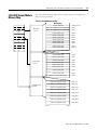
1
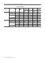
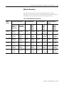
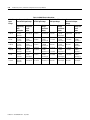
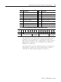
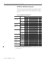
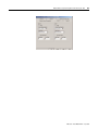
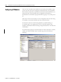
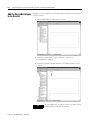
4-26
Module Data, Status, and Channel Configuration for the Output Modules
For example, an application may set the high clamp on a 1769-OF8C module
for 15 mA and the low clamp for 5 mA. If a controller sends a value
corresponding to 16 mA to the module, the module will only apply 15 mA to
its screw terminals.
Clamping is disabled on a per channel basis by entering a 0 value for both the
high and low clamps in the Configuration Data file. Interrupts are generated
on a high- or low-alarm by setting (1) the SIO bit (for high-clamp or
over-range alarm) or setting (1) the SIU bit (for low-clamp or under-range
alarm). Alarms caused by exceeding over-/under-range or clamp limits can be
latched by setting (1) a channel’s LA bit on a per channel basis.
Clamp/Limit Alarms
This function works directly with clamping. When a module receives a data
value from the controller that exceeds clamping limits, it applies signal values
at the clamping limit but also sends a status bit to the controller notifying it
that the value sent exceeds the clamping limits.
With reference to the example in the Clamping/Limiting section, if a
1769-OF8C module has clamping limits of 15 mA and 5 mA but then receives
data to apply 16 mA, only 15 mA is applied to the screw terminals. The
module sends a status bit back to the controller informing it that the 16 mA
value exceeds the module’s clamping limits.
Ramping
Ramping limits the speed at which an analog output signal can change. This
prevents fast transitions in the output from damaging the devices that an
output module controls.
Table 4.14 Ramping Types
Ramping Type
Description
Ramp to Fault Mode
This type of ramping occurs when the
present output value changes to the Fault
Value after a communications fault occurs.
This is the only type of ramping for the
1769-OF8C and -OF8V modules.
The ramp rate is defined in terms of the selected range/format in units per
second. For example, in the 0 to 20 mA range and percent of full scale format,
a ramp rate of 1000 is 10%/second (since 1000 is 10% of the total number of
counts in the full scale of the 0 to 20 mA range) or a maximum of 2 mA per
second. Table 4.15 and Table 4.16 describes how ramp rate is defined for all
output range/types and output data formats.
Publication 1769-UM002B-EN-P - July 2005