1
USER'S MANUAL
Fuji Electric FA Components & Systems Co., Ltd.
Mitsui Sumitomo Bank Ningyo-cho Bldg.,
5-7, Nihonbashi Odemma-cho, Chuo-ku, Tokyo 103-0011, Japan
Phone: +81-3-5847-8011 Fax: +81-3-5847-8172
Information in this manual is subject to change without notice.
Printed in Japan 2008-3 (F08a/F07) CM 10 FIS
MEH278a
背厚18.5mm
FRENIC Multi ユーザーズマニュアル_EC■M■Y■K■
High Performance, Multifunction Inverter
User's Manual
Copyright © 2007-2008 Fuji Electric FA Components & Systems Co., Ltd.
All rights reserved.
No part of this publication may be reproduced or copied without prior written permission from Fuji Electric
FA Components & Systems Co., Ltd.
All products and company names mentioned in this manual are trademarks or registered trademarks of their
respective holders.
The information contained herein is subject to change without prior notice for improvement.
Preface
This manual provides all the information on the FRENIC-MEGA series of inverters including its operating
procedure, operation modes, and selection of peripheral equipment. Carefully read this manual for proper use.
Incorrect handling of the inverter may prevent the inverter and/or related equipment from operating correctly,
shorten their lives, or cause problems.
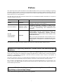
The table below lists the other materials related to the use of the FRENIC-MEGA. Read them in conjunction
with this manual as necessary.
Name
Material No.
Description
Catalog
MEH642
Product scope, features, specifications,
drawings, and options of the product
Instruction Manual
INR-SI47-1183-E
INR-SI47-1223-E
Acceptance inspection, mounting & wiring of the
inverter, operation using the keypad, running the motor
for a test, troubleshooting, and maintenance and
inspection
RS-485
Communication
User's Manual
MEH448
external
Overview of functions implemented by using
FRENIC-MEGA RS-485 communications facility, its
communications specifications, Modbus RTU/Fuji
general-purpose inverter protocol and functions, and
related data formats
Note: The RS-485 Communication User's Manual is as of
September 2005. Although it does not specifically refer to the
FRENIC-MEGA, all descriptions are intended for all types of
inverters.
The materials are subject to change without notice. Be sure to obtain the latest editions for use.
Guideline for Suppressing Harmonics in Home Electric and General-purpose
Appliances
Our three-phase, 200 V class series inverters of 3.7 kW or less (FRENIC-MEGA series) were the products of
which were restricted by the "Guideline for Suppressing Harmonics in Home Electric and General-purpose
Appliances" (established in September 1994 and revised in October 1999) issued by the Ministry of
Economy, Trade and Industry.
The above restriction, however, was lifted when the Guideline was revised in January 2004. Since then, the
inverter makers have individually imposed voluntary restrictions on the harmonics of their products.
We, as before, recommend that you connect a reactor (for suppressing harmonics) to your inverter. As a
reactor, select a "DC REACTOR" introduced in this manual. For use of the other reactor, please inquire of us
about detailed specifications.
Japanese Guideline for Suppressing Harmonics by Customers Receiving
High Voltage or Special High Voltage
Refer to this manual, Appendix B for details on this guideline.
i
Safety precautions
Read this manual and the FRENIC-MEGA Instruction Manual (INR-SI47-1183-E, INR-SI47-1223-E)
thoroughly before proceeding with installation, connections (wiring), operation, or maintenance and
inspection. Ensure you have sound knowledge of the product and familiarize yourself with all safety
information and precautions before proceeding to operate the inverter.
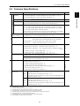
Safety precautions are classified into the following two categories in this manual.
Failure to heed the information indicated by this symbol may lead to
dangerous conditions, possibly resulting in death or serious bodily injuries.
Failure to heed the information indicated by this symbol may lead to
dangerous conditions, possibly resulting in minor or light bodily injuries
and/or substantial property damage.
Failure to heed the information contained under the CAUTION title can also result in serious consequences.
These safety precautions are of utmost importance and must be observed at all times.
This product is not designed for use in appliances and machinery on which lives depend. Consult your Fuji
Electric representative before considering the FRENIC-MEGA series of inverters for equipment and
machinery related to nuclear power control, aerospace uses, medical uses or transportation. When the
product is to be used with any machinery or equipment on which lives depend or with machinery or
equipment which could cause serious loss or damage should this product malfunction or fail, ensure that
appropriate safety devices and/or equipment are installed.
ii
How this manual is organized
This manual contains Chapters 1 through 9, Appendices, Glossary and Index.
Chapter 1 INTRODUCTION TO FRENIC-MEGA
This chapter describes the features and control system of the FRENIC-MEGA series and the recommended
configuration for the inverter and peripheral equipment.
Chapter 2 SPECIFICATIONS
This chapter describes specifications of the output ratings, control system, and terminal functions for the
FRENIC-MEGA series of inverters. It also provides descriptions of the operating and storage environment,
product warranty, precautions for use, external dimensions, examples of basic connection diagrams, and
details of the protective functions.
Chapter 3 SELECTING OPTIMAL MOTOR AND INVERTER CAPACITIES
This chapter provides you with information about the inverter output torque characteristics, selection
procedure, and equations for calculating capacities to help you select optimal motor and inverter models. It
also helps you select braking resistors, HD/LD drive mode, and motor drive control.
Chapter 4 SELECTING PERIPHERAL EQUIPMENT
This chapter describes how to use a range of peripheral equipment and options, FRENIC-MEGA's
configuration with them, and requirements and precautions for selecting wires and crimp terminals.
Chapter 5 FUNCTION CODES
This chapter contains overview tables of 12 groups of function codes available for the FRENIC-MEGA series
of inverters, function code index by purpose, and details of function codes.
Chapter 6 BLOCK DIAGRAMS FOR CONTROL LOGIC
This chapter provides the main block diagrams for the control logic of the FRENIC-MEGA series of
inverters.
Chapter 7 KEYPAD FUNCTIONS (OPERATING WITH THE KEYPAD)
This chapter describes the names and functions of the keypad and inverter operation using the keypad. The
inverter features three operation modes (Running, Programming and Alarm modes) which enable you to run
and stop the motor, monitor running status, set function code data, display running information required for
maintenance, and display alarm data.
Chapter 8 RUNNING THROUGH RS-485 COMMUNICATION
This chapter describes an overview of inverter operation through the RS-485 communications facility. Refer
to the RS-485 Communication User's Manual (MEH448) for details.
Chapter 9 TROUBLESHOOTING
This chapter describes troubleshooting procedures to be followed when the inverter malfunctions or detects
an alarm or a light alarm condition. In this chapter, first check whether any alarm code or the "light alarm"
indication (l-al) is displayed or not, and then proceed to the troubleshooting items.
Appendices
Glossary
Index
iii
Icons
The following icons are used throughout this manual.
This icon indicates information which, if not heeded, can result in the inverter not operating to
full efficiency, as well as information concerning incorrect operations and settings which can
result in accidents.
This icon indicates information that can prove handy when performing certain settings or
operations.
This icon indicates a reference to more detailed information.
iv
CONTENTS
Chapter 1 INTRODUCTION TO FRENIC-MEGA
1.1
Features..................................................................................................................................................... 1-1
1.2
Control System ....................................................................................................................................... 1-12
1.2.1 Theory of inverter ............................................................................................................................. 1-12
1.2.2 Motor drive controls.......................................................................................................................... 1-13
1.3
External View and Terminal Blocks ....................................................................................................... 1-14
1.4
Recommended Configuration ................................................................................................................. 1-16
Chapter 2 SPECIFICATIONS
2.1
Standard Models ....................................................................................................................................... 2-1
2.1.1 Three-phase 200 V class series (HD- and LD-mode inverters)........................................................... 2-1
2.1.2 Three-phase 400 V class series (HD- and LD-mode inverters)........................................................... 2-2
2.2
Common Specifications............................................................................................................................ 2-3
2.3
Terminal Specifications .......................................................................................................................... 2-10
2.3.1 Terminal functions ............................................................................................................................ 2-10
2.3.2 Terminal arrangement diagram and screw specifications.................................................................. 2-22
2.3.2.1 Main circuit terminals ............................................................................................................... 2-22
2.3.2.2 Control circuit terminals............................................................................................................ 2-24
2.4
Operating Environment and Storage Environment ................................................................................. 2-25
2.4.1 Operating environment...................................................................................................................... 2-25
2.4.2 Storage environment ......................................................................................................................... 2-26
2.4.2.1 Temporary storage..................................................................................................................... 2-26
2.4.2.2 Long-term storage ..................................................................................................................... 2-26
2.5
Precautions for Using Inverters .............................................................................................................. 2-27
2.5.1 Precautions in introducing inverters.................................................................................................. 2-27
2.5.2 Precautions in running inverters........................................................................................................ 2-32
2.5.3 Precautions in using special motors .................................................................................................. 2-32
2.6
External Dimensions............................................................................................................................... 2-34
2.6.1 Standard models ................................................................................................................................ 2-34
2.6.2 Keypad .............................................................................................................................................. 2-38
2.7
Connection Diagrams ............................................................................................................................. 2-39
2.7.1 Running a standard motor ................................................................................................................. 2-39
2.7.2 Running a Fuji motor exclusively designed for vector control ......................................................... 2-41
2.8
Protective Functions ............................................................................................................................... 2-43
Chapter 3 SELECTING OPTIMAL MOTOR AND INVERTER CAPACITIES
3.1
Selecting Motors and Inverters ................................................................................................................. 3-1
3.1.1 Motor output torque characteristics..................................................................................................... 3-1
3.1.2 Selection procedure............................................................................................................................. 3-4
3.1.3 Equations for selections ...................................................................................................................... 3-7
3.1.3.1 Load torque during constant speed running ................................................................................ 3-7
3.1.3.2 Acceleration and deceleration time calculation........................................................................... 3-9
3.1.3.3 Heat energy calculation of braking resistor............................................................................... 3-14
3.1.3.4 Calculating the RMS rating of the motor .................................................................................. 3-15
3.2
Selecting a Braking Resistor................................................................................................................... 3-16
3.2.1 Selection procedure........................................................................................................................... 3-16
3.2.2 Notes on selection ............................................................................................................................. 3-16
3.3
Selecting an Inverter Drive Mode........................................................................................................... 3-17
3.3.1 Precaution to inverter drive mode selection between HD and LD modes......................................... 3-17
3.3.2 Guideline for selecting inverter drive mode and capacity................................................................. 3-17
3.4
Selecting a Motor Drive Control............................................................................................................. 3-18
3.4.1 Features of motor drive control......................................................................................................... 3-18
v
Chapter 4 SELECTING PERIPHERAL EQUIPMENT
4.1
Configuring the FRENIC-MEGA............................................................................................................. 4-1
4.2
Selecting Wires and Crimp Terminals....................................................................................................... 4-2
4.2.1 Recommended wires ........................................................................................................................... 4-5
4.3
Peripheral Equipment ............................................................................................................................... 4-9
4.3.1 Molded case circuit breaker (MCCB), residual-current-operated protective device (RCD)/
earth leakage circuit breaker (ELCB) and magnetic contactor (MC).................................................. 4-9
4.3.2 Surge killers for L-load ..................................................................................................................... 4-13
4.3.3 Arresters ............................................................................................................................................ 4-14
4.3.4 Surge absorbers ................................................................................................................................. 4-15
4.3.5 Filtering capacitors suppressing AM radio band noises .................................................................... 4-16
4.4
Selecting Options.................................................................................................................................... 4-17
4.4.1 Peripheral equipment options............................................................................................................ 4-17
4.4.1.1 Braking resistor (DBR) and braking unit .................................................................................. 4-17
4.4.1.2 Power regenerative PWM converter, RHC series ..................................................................... 4-24
4.4.1.3 DC reactors (DCRs) .................................................................................................................. 4-25
4.4.1.4 AC reactors (ACRs) .................................................................................................................. 4-28
4.4.1.5 Surge suppression unit (SSU).................................................................................................... 4-31
4.4.1.6 Output circuit filters (OFLs)...................................................................................................... 4-32
4.4.1.7 Zero-phase reactor for reducing radio noise (ACL) .................................................................. 4-35
4.4.2 Options for operation and communications ...................................................................................... 4-36
4.4.2.1 External frequency command potentiometer............................................................................. 4-36
4.4.2.2 Extension cable for remote operation........................................................................................ 4-37
4.4.2.3 Inverter support loader software................................................................................................ 4-38
4.4.2.4 PG interface card (option) ......................................................................................................... 4-39
4.4.2.5 Relay output card (option)......................................................................................................... 4-42
4.4.3 Meter options .................................................................................................................................... 4-44
4.4.3.1 Frequency meters ...................................................................................................................... 4-44
Chapter 5 FUNCTION CODES
5.1
Overview of Function Codes .................................................................................................................... 5-1
5.2
Function Code Tables ............................................................................................................................... 5-2
5.3
Function Code Index by Purpose............................................................................................................ 5-23
5.3.1 Configuring the minimal requirements for the inverter to just run the motor ................................... 5-23
5.3.2 Setting up the frequency.................................................................................................................... 5-23
5.3.2.1 Frequency setting from the keypad ........................................................................................... 5-23
5.3.2.2 Frequency setting by analog input............................................................................................. 5-24
5.3.2.3 Other frequency settings............................................................................................................ 5-24
5.3.3 Entering a run command ................................................................................................................... 5-25
5.3.4 Starting/stopping the motor............................................................................................................... 5-26
5.3.5 Specifying the acceleration/deceleration (time, mode, and pattern).................................................. 5-26
5.3.6 Adjusting the running performance................................................................................................... 5-27
5.3.7 Controlling the motor........................................................................................................................ 5-28
5.3.7.1 Motor drive control to be selected............................................................................................. 5-28
5.3.7.2 Motor constants to be set........................................................................................................... 5-29
5.3.8 Setting up I/O terminals .................................................................................................................... 5-29
5.3.9 Outputting monitored data ................................................................................................................ 5-30
5.3.10 Keeping on running the motor .......................................................................................................... 5-30
5.3.11 Outputting status signals ................................................................................................................... 5-31
5.3.12 Running in various operation modes................................................................................................. 5-32
5.3.13 Setting up controls suited for individual applications ....................................................................... 5-33
5.3.13.1 Droop control ............................................................................................................................ 5-33
5.3.13.2 PID process control ................................................................................................................... 5-33
5.3.13.3 PID dancer control .................................................................................................................... 5-35
5.3.14 Customizing the keypad.................................................................................................................... 5-37
5.3.15 Controlling the inverter via communications line ............................................................................. 5-38
5.3.16 Activating the protective functions ................................................................................................... 5-39
vi
5.3.16.1 Protection of machinery with limiters ....................................................................................... 5-39
5.3.16.2 Protection of motors .................................................................................................................. 5-39
5.3.16.3 Using other protective and safety functions .............................................................................. 5-40
5.3.17 Maintenance ...................................................................................................................................... 5-42
5.3.17.1 Maintenance of inverters ........................................................................................................... 5-42
5.3.17.2 Maintenance of machinery ........................................................................................................ 5-42
5.4
Details of Function Codes....................................................................................................................... 5-43
5.4.1 F codes (Fundamental functions) ...................................................................................................... 5-43
5.4.2 E codes (Extension terminal functions)............................................................................................. 5-91
5.4.3 C codes (Control functions) ............................................................................................................ 5-128
5.4.4 P codes (Motor parameters) ............................................................................................................ 5-133
5.4.5 H codes (High performance functions) ........................................................................................... 5-138
5.4.6 A codes (Motor 2 parameter) b codes (Motor 3 parameter) r codes (Motor 4 parameter) .............. 5-174
5.4.7 J codes (Application functions 1).................................................................................................... 5-177
5.4.8 d codes (Application functions 2) ................................................................................................... 5-194
5.4.9 y codes (Link functions).................................................................................................................. 5-199
Chapter 6 BLOCK DIAGRAMS FOR CONTROL LOGIC
6.1
Symbols Used in Block Diagrams and their Meanings ............................................................................ 6-1
6.2
Drive Frequency Command Block ........................................................................................................... 6-2
6.3
Drive Command Block ............................................................................................................................. 6-4
6.4
Control Block............................................................................................................................................ 6-6
6.4.1 V/f control ........................................................................................................................................... 6-6
6.4.2 Vector control with speed sensor......................................................................................................... 6-8
6.5
PID Process Control Block ..................................................................................................................... 6-10
6.6
PID Dancer Control Block...................................................................................................................... 6-12
6.7
FMA/FMP Output Selector..................................................................................................................... 6-14
Chapter 7 KEYPAD FUNCTIONS (OPERATING WITH THE KEYPAD)
7.1
LED Monitor, Keys and LED Indicators on the Keypad .......................................................................... 7-1
7.2
Overview of Operation Modes ................................................................................................................. 7-4
7.3
Running Mode .......................................................................................................................................... 7-6
7.3.1 Monitoring the running status ............................................................................................................. 7-6
7.3.2 Monitoring light alarms....................................................................................................................... 7-8
7.3.3 Setting up frequency and PID commands ........................................................................................... 7-9
7.3.4 Running/stopping the motor.............................................................................................................. 7-14
7.3.5 Jogging Operation ............................................................................................................................. 7-14
7.3.6 Remote and local modes ................................................................................................................... 7-15
7.3.7 External run/frequency command ..................................................................................................... 7-16
7.4
Programming Mode ................................................................................................................................ 7-17
7.4.1 Setting up basic function codes quickly -- Menu #0 "Quick Setup" --.............................................. 7-19
7.4.2 Setting up function codes -- Menu #1 "Data Setting" --................................................................... 7-22
7.4.3 Checking changed function codes -- Menu #2 "Data Checking" -- .................................................. 7-25
7.4.4 Monitoring the running status -- Menu #3 "Drive Monitoring" -- ................................................... 7-26
7.4.5 Checking I/O signal status -- Menu #4 "I/O Checking" -- ............................................................... 7-30
7.4.6 Reading maintenance information -- Menu #5 "Maintenance Information" -- ................................ 7-35
7.4.7 Reading alarm information -- Menu #6 "Alarm Information" --...................................................... 7-40
7.4.8 Copying data -- Menu #7 "Data Copying" -- ................................................................................... 7-43
7.5
Alarm Mode............................................................................................................................................ 7-46
7.5.1 Releasing the alarm and switching to Running mode ....................................................................... 7-46
7.5.2 Displaying the alarm history ............................................................................................................. 7-46
7.5.3 Displaying the status of inverter at the time of alarm ....................................................................... 7-46
7.5.4 Switching to Programming mode...................................................................................................... 7-46
7.6
USB Connectivity................................................................................................................................... 7-48
vii
Chapter 8 RUNNING THROUGH RS-485 COMMUNICATION
8.1
Overview on RS-485 Communication...................................................................................................... 8-1
8.1.1 RS-485 common specifications........................................................................................................... 8-2
8.1.2 Terminal specifications for RS-485 communications ......................................................................... 8-3
8.1.3 Connection method ............................................................................................................................. 8-4
8.1.4 Communications support devices........................................................................................................ 8-6
8.1.5 Noise suppression................................................................................................................................ 8-7
8.2
Overview of FRENIC Loader................................................................................................................... 8-8
8.2.1 Specifications ...................................................................................................................................... 8-8
8.2.2 Connection .......................................................................................................................................... 8-9
8.2.3 Function overview............................................................................................................................... 8-9
8.2.3.1 Setting of function code .............................................................................................................. 8-9
8.2.3.2 Multi-monitor............................................................................................................................ 8-10
8.2.3.3 Running status monitor ............................................................................................................. 8-11
8.2.3.4 Test-running .............................................................................................................................. 8-12
8.2.3.5 Real-time trace—Displaying running status of an inverter in waveforms ................................ 8-13
8.2.3.6 Historical trace (Available soon) ............................................................................................... 8-14
8.2.3.7 USB port on the standard keypad.............................................................................................. 8-15
Chapter 9 TROUBLESHOOTING
9.1
Protective Functions ................................................................................................................................. 9-1
9.2
Before Proceeding with Troubleshooting ................................................................................................. 9-3
9.3
If Neither an Alarm Code Nor "Light Alarm" Indication (l-al) Appears on the LED Monitor............ 9-4
9.3.1 Abnormal motor operation .................................................................................................................. 9-4
9.3.2 Problems with inverter settings ......................................................................................................... 9-10
9.4
If an Alarm Code Appears on the LED Monitor ..................................................................................... 9-11
9.5
If the "Light Alarm" Indication (l-al) Appears on the LED Monitor................................................. 9-25
9.6
If an Abnormal Pattern Appears on the LED Monitor while Neither an Alarm Code nor
"Light Alarm" Indication (l-al) is Displayed ..................................................................................... 9-26
Appendices
App. A Advantageous Use of Inverters (Notes on electrical noise)................................................................... A-1
A.1 Effect of inverters on other devices ....................................................................................................... A-1
A.2 Noise...................................................................................................................................................... A-2
A.3 Noise prevention.................................................................................................................................... A-4
App. B Japanese Guideline for Suppressing Harmonics by Customers Receiving High Voltage or
Special High Voltage ........................................................................................................................... A-12
B.1 Application to general-purpose inverters............................................................................................. A-12
B.2 Compliance to the harmonic suppression for customers receiving high voltage or
special high voltage ............................................................................................................................. A-13
App. C Effect on Insulation of General-purpose Motors Driven with 400 V Class Inverters.......................... A-17
C.1 Generating mechanism of surge voltages ............................................................................................ A-17
C.2 Effect of surge voltages ....................................................................................................................... A-18
C.3 Countermeasures against surge voltages ............................................................................................. A-18
C.4 Regarding existing equipment ............................................................................................................. A-19
App. D Inverter Generating Loss ..................................................................................................................... A-20
App. E Conversion from SI Units.................................................................................................................... A-21
App. F Allowable Current of Insulated Wires ................................................................................................. A-23
App. G Replacement Information .................................................................................................................... A-25
G.1 External dimensions comparison tables............................................................................................... A-25
G.2 Terminal arrangements and symbols ................................................................................................... A-28
G.3 Function codes..................................................................................................................................... A-35
Glossary
Index
viii
Chapter 1
INTRODUCTION TO FRENIC-MEGA
This chapter describes the features and control system of the FRENIC-MEGA series and the recommended
configuration for the inverter and peripheral equipment.
Contents
1.1 Features....................................................................................................................................................... 1-1
1.2 Control System.......................................................................................................................................... 1-12
1.2.1 Theory of inverter ............................................................................................................................. 1-12
1.2.2 Motor drive controls.......................................................................................................................... 1-13
1.3 External View and Terminal Blocks.......................................................................................................... 1-14
1.4 Recommended Configuration ................................................................................................................... 1-16
1.1 Features
Chap. 1
1.1 Features
Ideal for highly accurate control such as positioning
Vector control with speed sensor
Effective for applications requiring highly precise and accurate positioning control such as offset
printing
Speed control range: 1:1500
Speed response: 100 Hz
Speed control accuracy: ±0.01%
Current response: 500 Hz
Torque accuracy: ±10%
* The option card is required.
* The above specifications may vary depending on
the environment or conditions for use.
Maximizing the performance of a general-purpose motor
Vector control without speed sensor (available soon)
Useful for the application that requires a high starting torque, such as the gondola type multi-level car
parking tower
Speed control range: 1:200
Speed response: 20 Hz
Speed control accuracy: ±0.5%
Current response: 500 Hz
Torque accuracy: ±10%
1-1
INTRODUCTION TO FRENIC-MEGA
Best vector control for the general-purpose inverter in the class
Fuji's original dynamic torque vector control has further upgraded.
Besides the dynamic torque vector control, the inverter is equipped with the motor parameter tuning
for compensating even a voltage error of the main circuit devices and the magnetic flux observer of a
new system. This realizes a high starting torque of 200% even at a low-speed rotation of 0.3 Hz.
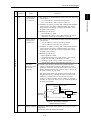
Improved reaction to the fluctuation of impact load
When a remarkable load fluctuation occurs, the inverter provides the torque response in the class-top
level. It controls the flux to minimize the fluctuation in the motor speed while suppressing the
vibration. This function is best suited for equipment that requires stable speed such as a cutting
machine.
Example:
1-2
1.1 Features
Current overload durability: 200% for 3 seconds and 150% for 1 minute.
The standard model is available in the following two drive modes concerning the operation load.
Drive mode
Current overload durability
Major application
HD (High duty) mode
200% for 3 sec, 150% for 1 min
Operation under heavy load
LD (Low duty) mode
120% for 1 min
Operation under light load
Quicker response to the operation commands
The terminal response to the operation commands has had an established reputation. The
FRENIC-MEGA has further shortened this response time, achieving the industry-top response time.
This function is effective in shortening the tact time per cycle and effective for use in the process
including frequent repetitions.
Example:
Output
current
Control terminal signal
(Run command)
Expanded capacity for the brake switching circuit built-in type
A brake switching circuit is built in inverters with a capacity of 22 kW or less as standard. These
inverters are applicable to vertical carrier machines and others that run with a certain regenerative load.
(Inverters with a capacity of 7.5 kW or less also integrate a braking resistor.)
The brake switching circuit built-in type of inverters with a capacity of 30 to 55 kW in 200 V class
series and 30 to 110 kW in 400 V class series is available on request.
1-3
INTRODUCTION TO FRENIC-MEGA
Enhancement for extending the current overload durability time of the FRENIC-MEGA longer than
that of the Fuji conventional inverters allows the FRENIC-MEGA to run the motor with shorter
acceleration/deceleration time. This improves the operation efficiency of machinery such as cutting
machines or carrier machines.
Chap. 1
Improved durability in overload operation
Accommodating various applications
Convenient functions for operations at the specified speed
Pulse train input speed command supported as standard
The FRENIC-MEGA can issue a speed command with the pulse train input (single-phase pulse train
with sign).
(Maximum pulse input: 100 kHz)
Ratio operation
The ratio operation is convenient for synchronous control of two or more carrier machines in a
multiline conveyor system. It is possible to specify the ratio of the main speed to other follower motors
as a frequency command, so the conveying speed of carrier machines that handle variable loads or
loading situations can be synchronously adjusted easily.
Frequency command output = Frequency command input ×
Analog input (Ratio setting)
100%
Optimum function for preventing an object from slipping down
The reliability of the brake signal was increased for uses such as vertical carrier machines.
Conventionally, the current value and the frequency have been monitored when the brake signal is
output. By adding a torque value to these two values, the brake timing can be adjusted more easily.
1-4
1.1 Features
Thorough protection of the braking circuit
The inverter monitors the braking transistor operation status to protect the braking resistor. Upon
detection of a braking transistor abnormality, the inverter outputs an exclusive signal. Provide
such a circuit that shuts the input power off upon receipt of the exclusive signal, outside the inverter
for protecting the braking circuit.
More functions are available to meet various requirements
(1) Analog input: Two terminals for voltage input with polarity and one terminal for current input
(2) Slow flowrate level stop function (Pressurized operation is possible before stop of slow flowrate
operation.)
(3) Non-linear V/f pattern at 3 points
(4) Mock alarm output function
(5) Selection of up to the 4th motor
(6) S-curve accel./decel. range setting
(7) Detection of a PID feedback wire break
1-5
INTRODUCTION TO FRENIC-MEGA
The PID value, calculated by comparing the feedback value with the speed command value, is added
to or subtracted from the reference speed. Since the PID processor gain (in proportional band) can be
set low, the inverter can be applied to automatic control systems requiring quick response such as
speed control.
Chap. 1
Dancer control function optimum for winding control
Wide model variation meeting the customer needs
Wide model variation
1. Basic type
Suitable for the equipment that uses a peripheral device to suppress noise or harmonics.
2. EMC filter built-in type (available soon)
This type has a built-in EMC filter and is compliant with European EMC Directives.
Objective standard: Category C3 (2nd Env) EN61800-3:2004 compliant
* Use of EMC filter will increase the leakage current.
3. Inverter type designed to the guideline specified by the Ministry of Land, Infrastructure and
Transport (available soon)
The inverter employs a DC reactor and complies with "Standard Specifications for Public Building
Construction" supervised by the Ministry of Land, Infrastructure and Transport. This inverter
suppresses harmonics and noise.
* The inverter incorporates the DC reactor, and the zero-phase reactor is supplied together with the
inverter to meet the inverter installation standards stipulated in the Standard Specifications for
Public Building Construction (Electric Equipment) 2004 version published under the supervision by
Government Buildings Department in Minister/Secretariat of Land, Infrastructure and Transport.
1-6
1.1 Features
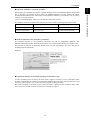
Improved working efficiency in the manufacturing site
- A variety of data about the inverter body can be saved in the keypad memory, allowing you to check
the information in any place.
Example of use in the office
Features
1. The keypad can be directly connected to the computer
through a commercial USB cable (mini B) without using a
converter. The computer can be connected on-line with the
inverter.
2. With the FRENIC loader, the inverter can support the
following functions (1) to (5).
(1) Editing, comparing, and copying the function code data
(2) Operation monitor, real-time trace
(3) Trouble history (indicating the latest four trouble records)
(4) Maintenance information
(5) Historical trace (available soon)
- Data can be directly transferred from the keypad via the USB port to the computer (FRENIC loader)
at the manufacturing site.
- Periodical collection of life information can be carried out efficiently.
- The real-time tracing function permits the operator to check the inverter for abnormality.
Example of use at the manufacturing site
1-7
INTRODUCTION TO FRENIC-MEGA
The built-in USB port allows use of an inverter support loader (FRENIC loader) for easy
information control!
Chap. 1
Supports for simple maintenance
Network connectivity
Connectivity to the various FA networks with the following option cards (available soon)
- SX bus interface card
- T-link interface card
- PROFIBUS-DP interface card
- DeviceNet interface card
- CANopen interface card
- CC-Link interface card
RS-485 communication possible as standard (on the terminal block)
Besides the port (RJ-45 connector) shared with the keypad, an RS-485 terminal is provided as standard.
With the terminal connection, multi-drop connection can be made easily.
1-8
1.1 Features
Designed life 10 years
Consumable part
Designed life
Main circuit capacitor
10 years
Electrolytic capacitor on PCB
10 years
Cooling fan
10 years
The part life conditions that the inverter is used at:
a surrounding temperature of 40ºC and under the load rate of 100% (HD mode) or 80% (LD mode)
* The designed lives are the calculated values and not the guaranteed ones.
Full support of life warnings
The inverter has the following functions for facilitating the maintenance of the machinery.
Item
Purpose
Cumulative run time (Unit: h)
Displays the total run time of the inverter by counting the
ON time of the main power, by hours.
Cumulative motor run time
(Unit: 10 hours)
Displays the total run time of the motor.
Used to judge the service life of machinery (load).
Even when the motor is driven by commercial power, it is
also possible to count the cumulative motor run time using
digital input signals.
Cumulative startup count
Displays the number of motor startups.
This count can be used as a guide for replacement timing of
machinery parts (such as timing belts) that undergo load in
ordinary operation.
Equipment maintenance warning
Cumulative motor run time
(Unit: 10 hours)
Cumulative startup count
Makes it possible manage the total run time of the motor
and the number of startups. Such data is usable for
preparing the maintenance schedule.
Display of inverter lifetime alarm
Displays the following:
- Current capacitance of DC link bus capacitor
- Total run time of the cooling fan (with ON/OFF
compensation)
- Total run time of the electrolytic capacitor on the printed
circuit board
1-9
INTRODUCTION TO FRENIC-MEGA
For the various consumable parts inside the inverter, their designed lives have been extended to 10
years, which also extended the equipment maintenance cycles.
Chap. 1
Prolonged service life and improved life judgment function
Consideration for environment
Enhanced resistance to the environmental impacts
Resistance to the environmental impact has been enhanced compared with the conventional inverter.
(1) Enhanced durability of the cooling fan operated under the environmental impact
(2) Adoption of copper bars plated with nickel or tin
In MEGA, resistance to the environmental impact has been increased compared with the conventional
model (FRENIC5000 G11S/P11S). However, examine the use of the inverter carefully according to
the environment in the following cases:
a. Environment is subject to sulfide gas (at tire manufacturer, paper manufacturer, sewage disposer, or
part of the process in textile industry).
b. Environment is subject to conductive dust or foreign matters (in metalworking, operation using
extruding machine or printing machine, waste disposal).
c. Others: The inverter is used in the environment of which specification exceeds the specified range.
If you are examining use of the inverter under the above conditions, consult us regarding the models
with enhanced durability.
Protection against micro surge (optional)
Surge suppression unit SSU (optional)
If the motor drive cable is long, a very thin surge voltage (micro surge) is generated at the motor
connection ends. This surge voltage causes deterioration of the motor, dielectric breakdown, or
increase in noise. Using the surge suppression unit suppresses this surge voltage.
(1) The surge suppression unit significantly suppresses the surge voltage when simply connected with
the motor.
(2) Since no additional work is required, it can be easily mounted on the existing equipment.
(3) The unit is applicable to the motors regardless of their capacity. (However, consult us for
application to the motor with a capacity of 75 kW or over.)
(4) The unit requires no power source and no maintenance.
(5) Two types are available; One for 50m motor cable and the other for 100m motor cable.
(6) Compliant with environmental standard and safety standard (Compliant with RoHS Directives,
and application to UL standard pending).
Surge suppression unit structure
1-10
1.1 Features
<Six hazardous substances>
Lead, mercury, cadmium, hexavalent chromium, polybrominated biphenyl (PBB), and
polybrominated biphenyl ether (PBDE)
* Except the parts of some inverter models
<About RoHS>
The Directive 2002/96/EC, promulgated by the European Parliament and European Council, limits the
use of specific hazardous substances included in electrical and electronic devices.
Global compliance
Application to global standards pending
1-11
INTRODUCTION TO FRENIC-MEGA
MEGA complies with European regulations that limit the use of specific hazardous substances
(RoHS) as a standard. This inverter is environment-friendly as the use of the following six hazardous
substances is restricted.
Chap. 1
Compliance with RoHS Directives
1.2 Control System
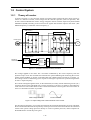
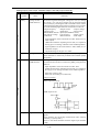
1.2.1
Theory of inverter
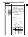
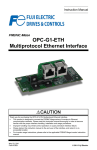
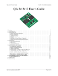
As shown in Figure 1.1, the converter section converts the input commercial power to DC power by
means of a full-wave rectifier, which charges the DC link bus capacitor (reservoir capacitor). The
inverter section modulates the electric energy charged in the DC link bus capacitor by Pulse Width
Modulation (PWM) according to the control circuit signals and feeds the output to the motor. (The
PWMed frequency is called the "Carrier Frequency.")
<Main circuit >
Converter
Inverter
Power supply
Motor
DC link bus
capacitor
+
M
<Control block>
Frequency
command
Accelerator
/decelerator
processor
V/f pattern
generator
V
f
3-phase
voltage
processor
PWM
Figure 1.1 Schematic Overview of Theory of Inverter
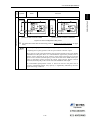
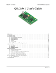
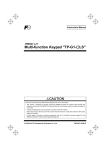
The voltage applied to the motor has a waveform modulated by the carrier frequency from the
dynamic torque vector flux controller that estimates the optimal PWM signal monitoring the inverter
output current feedback, as shown on the left-hand side ("PWM voltage waveform") of Figure 1.2.
The voltage consists of alternating cycles of positive and negative pulse trains synchronizing with the
inverter’s output frequency.
The current running through the motor, on the other hand, has a fairly smooth alternating current (AC)
waveform shown on the right-hand side ("Current waveform") of Figure 1.2, thanks to the inductance
of the motor coil. The control block section controls the PWM so as to bring this current waveform as
close to a sinusoidal waveform as possible.
PWM voltage waveform
Current waveform
Figure 1.2 Output Voltage and Current Waveform of the Inverter
For the reference frequency given in the control block, the accelerator/decelerator processor calculates
the acceleration/deceleration rate required by run/stop control of the motor and transfers the calculated
results to the 3-phase voltage processor directly or via the V/f pattern processor, whose output drives
the PWM block to switch the power gates.
1-12
1.2 Control System
Chap. 1
1.2.2
Motor drive controls
The FRENIC-MEGA supports the following motor drive controls.
Basic control
Speed feedback
V/f control
with slip compensation inactive
Dynamic torque vector control
Speed control
Frequency control
V/f control
Disable
V/f control
with slip compensation active
Vector control with speed sensor* Vector control
Enable
Frequency control
with slip compensation
active
Speed control with
automatic speed regulator
(ASR)
Additionally, the FRENIC-MEGA reserves motor drive controls shown below for future support
options.
- V/f control with speed sensor*
- Dynamic torque vector control with speed sensor*
- Vector control without speed sensor
The controls marked with an asterisk (*) require an optional PG (Pulse Generator) interface card.
For the features of the controls, refer to Chapter 3, Section 3.4.1 "Features of motor drive control."
1-13
INTRODUCTION TO FRENIC-MEGA
Drive control
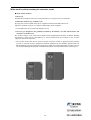
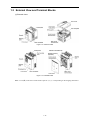
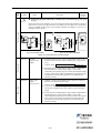
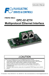
1.3 External View and Terminal Blocks
(1) External views
Figure 1.3 FRN11G1S-2
Figure 1.4 FRN30G1S-4
Note: A box () in the above model names replaces A, E, J, or T depending on the shipping destination.
1-14
1.3 External View and Terminal Blocks
Chap. 1
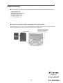
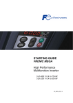
(2) Terminal block location
(b) FRN30G1S-2
Figure 1.5 Terminal Blocks and Keypad Enclosure Location
(a) FRN0.75G1S-2
(b) FRN30G1S-2
Figure 1.6 Enlarged View of the Terminal Blocks
Note: A box () in the above model names replaces A, E, J, or T depending on the shipping destination.
Refer to Chapter 2 "SPECIFICATIONS" for details on terminal functions, arrangement and
connection and to Chapter 4, Section 4.2.1 "Recommended wires" when selecting wires.
1-15
INTRODUCTION TO FRENIC-MEGA
(a) FRN11G1S-2
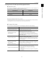
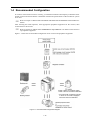
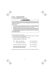
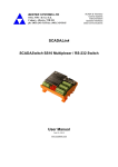
1.4 Recommended Configuration
To control a motor with an inverter correctly, you should consider the rated capacity of both the motor
and the inverter and ensure that the combination matches the specifications of the machine or system
to be used.
Refer to Chapter 3 "SELECTING OPTIMAL MOTOR AND INVERTER CAPACITIES" for
details.
After selecting the rated capacities, select appropriate peripheral equipment for the inverter, then
connect them to the inverter.
Refer to Chapter 4 "SELECTING PERIPHERAL EQUIPMENT" for details on the selection
of peripheral equipment.
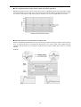
Figure 1.7 shows the recommended configuration for an inverter and peripheral equipment.
55 kW or below: Provided as option
75 kW or above: Provided as standard
* An inverter with a capacity of 55 kW
or above in LD mode is equipped
with a DC reactor as standard.
Figure 1.7 Recommended Configuration Diagram
1-16
Chapter 2
SPECIFICATIONS
This chapter describes specifications of the output ratings, control system, and terminal functions for the
FRENIC-MEGA series of inverters. It also provides descriptions of the operating and storage environment,
product warranty, precautions for using inverters, external dimensions, examples of basic connection
diagrams, and details of the protective functions.
Contents
2.1 Standard Models ......................................................................................................................................... 2-1
2.1.1 Three-phase 200 V class series (HD- and LD-mode inverters)........................................................... 2-1
2.1.2 Three-phase 400 V class series (HD- and LD-mode inverters)........................................................... 2-2
2.2 Common Specifications .............................................................................................................................. 2-3
2.3 Terminal Specifications............................................................................................................................. 2-10
2.3.1 Terminal functions ............................................................................................................................ 2-10
2.3.2 Terminal arrangement diagram and screw specifications.................................................................. 2-22
2.3.2.1 Main circuit terminals ............................................................................................................... 2-22
2.3.2.2 Control circuit terminals............................................................................................................ 2-24
2.4 Operating Environment and Storage Environment ................................................................................... 2-25
2.4.1 Operating environment...................................................................................................................... 2-25
2.4.2 Storage environment ......................................................................................................................... 2-26
2.4.2.1 Temporary storage..................................................................................................................... 2-26
2.4.2.2 Long-term storage ..................................................................................................................... 2-26
2.5 Precautions for Using Inverters................................................................................................................. 2-27
2.5.1 Precautions in introducing inverters.................................................................................................. 2-27
2.5.2 Precautions in running inverters........................................................................................................ 2-32
2.5.3 Precautions in using special motors .................................................................................................. 2-32
2.6 External Dimensions ................................................................................................................................. 2-34
2.6.1 Standard models ................................................................................................................................ 2-34
2.6.2 Keypad .............................................................................................................................................. 2-38
2.7 Connection Diagrams................................................................................................................................ 2-39
2.7.1 Running a standard motor ................................................................................................................. 2-39
2.7.2 Running a Fuji motor exclusively designed for vector control ......................................................... 2-41
2.8 Protective Functions.................................................................................................................................. 2-43
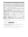
2.1 Standard Models
2.1 Standard Models
Three-phase 200 V class series (HD- and LD-mode inverters)
Chap. 2
2.1.1
SPECIFICATIONS
*1 Fuji 4-pole standard motor
*2 Rated capacity is calculated assuming the rated output voltage as 220 V for 200 V class series and 440 V for 400 V class
series.
*3 Output voltage cannot exceed the power supply voltage.
*4 To use the inverter with the carrier frequency of 3 kHz or more at the surrounding temperature of 40°C or higher, manage
the load so that the current comes to be within the rated ones enclosed in parentheses ( ) in continuous running.
*5 Voltage unbalance (%) = Max voltage (V) - Min voltage (V) × 67 (IEC61800-3)
Three-phase average voltage (V)
If this value is 2 to 3%, use an optional AC reactor (ACR).
*6 Required when a DC reactor (DCR) is used.
*7 Average braking torque for the motor running alone. (It varies with the efficiency of the motor.)
*8 For inverters with a capacity of 55 kW, a DCR is provided as standard or option for LD or HD mode, respectively.
Note: A box () in the above table replaces A, E, J, or T depending on the shipping destination.
2-1
2.1.2
Three-phase 400 V class series (HD- and LD-mode inverters)
*1
Fuji 4-pole standard motor
*2
Rated capacity is calculated assuming the rated output voltage as 220 V for 200 V class series and 440 V for 400 V class
series.
*3
Output voltage cannot exceed the power supply voltage.
*5 Voltage unbalance (%) = Max voltage (V) - Min voltage (V) × 67 (IEC61800-3)
Three-phase average voltage (V)
If this value is 2 to 3%, use an optional AC reactor (ACR).
*6
Required when a DC reactor (DCR) is used. A DCR is provided as standard for LD-mode inverters with a capacity of 55
kW and inverters with a capacity of 75 kW or above.
*7
Average braking torque for the motor running alone. (It varies with the efficiency of the motor.)
*8
*9
380 to 440 V, 50 Hz; 380 to 480 V, 60 Hz
For inverters with a capacity of 55 kW, a DCR is provided as standard or option for LD or HD mode, respectively.
Note: A box () in the above table replaces A, E, J, or T depending on the shipping destination.
2-2
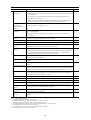
2.2 Common Specifications
2.2 Common Specifications
Setting range
Maximum
frequency
• 25 to 500 Hz (HD mode, V/f control *1, *2, *3)
• 25 to 200 Hz (HD mode, V/f control with PG/vector control with PG *4, *5, *7)
• 25 to 120 Hz (HD mode, vector control without speed sensor *6
LD mode, various controls *1 to *7)
Base frequency
25 to 500 Hz variable (120 Hz in LD mode)
Remarks
SPECIFICATIONS
Output frequency
Explanation
Starting frequency 0.1 to 60.0 Hz variable
(Vector control without speed sensor *6 / Vector control with PG, 0.0 Hz *7)
Carrier frequency
• 0.75 to 16 kHz variable setting (HD mode: 0.4 to 55 kW, LD mode: 5.5 to 18.5 kW)
• 0.75 to 10 kHz variable setting (HD mode: 75 to 400 kW, LD mode: 22 to 55 kW)
• 0.75 to 6 kHz variable setting (HD mode: 500 to 630 kW, LD mode: 75 to 500 kW)
• 0.75 to 4 kHz variable setting (LD mode: 630 kW)
Note: Frequency drops automatically to protect the inverter depending on environmental
temperature and output current. (This auto drop function can be canceled.)
• Analog setting:
±0.2% of maximum frequency (at 25±10°C) *1
Output frequency
accuracy (Stability)
• Keypad setting: ±0.01% of maximum frequency (at -10 to +50°C)
Setting resolution
• Analog setting:
1/3000 of maximum frequency (1/1500 with V2 input)
The resolution can be set in the function code. (0.01 to 500 Hz)
*8
• Keypad setting: 0.01 Hz (99.99 Hz or less), 0.1 Hz (100.0 to 500 Hz)
• Link setting:
Speed control range
1/20000 of maximum frequency or 0.01 Hz (fixed)
• Minimum speed : Base speed
• Minimum speed : Base speed
• Minimum speed : Base speed
1:1500 (4P 1 r/min to 1500 r/min) *7
1:200 (4P 7.5 r/min to 1500 r/min) *6
1:100 1:200 (4P 15 r/min to 1500 r/min, 1024 p/r)
*4,*5
• Constant torque range : Constant output range
1:4 *7
• Constant torque range : Constant output range
1:2 *4, *5, *6
Speed control accuracy • Analog setting: ±0.2% of maximum frequency (at 25 ±10°C) *4, *5, *7
• Digital setting: ±0.01% of maximum frequency (at -10 to +50°C)
*8
*8
*8
*8
• Analog setting: ±0.5% of base speed (at 25 ±10°C) *6
• Digital setting: ±0.5% of base speed (at -10 to +50°C)
Control
Control method
*1
*2
*3
*4
*5
*6
*7
*8
Voltage/frequency
characteristic
•
•
•
•
•
•
•
V/f control *1
Dynamic torque vector control *2
V/f control with slip compensation active *3
V/f control with speed sensor (PG option) *4
Dynamic torque vector control with speed sensor (PG option) *5
Vector control without speed sensor *6
Vector control with speed sensor (PG option) *7
200 V
class
series
• Possible to set output voltage at base frequency and at maximum output
frequency (80 to 240 V).
• The AVR control can be turned ON or OFF. *1, *4
• Non-linear V/f setting (3 points): Free voltage (0 to 240 V) and frequency (0 to
500 Hz) can be set. *1, *4
400 V
class
series
• Possible to set output voltage at base frequency and at maximum output
frequency (160 to 500 V).
• The AVR control can be turned ON or OFF. *1, *4
• Non-linear V/f setting (3 points): Free voltage (0 to 240 V) and frequency (0 to
500 Hz) can be set. *1, *4
Available under V/f control.
Available under dynamic torque vector control.
Available when the slip compensation is made active under V/f control.
Available under V/f control with speed sensor. (PG option required)
Available under dynamic torque vector control with speed sensor. (PG option required)
Available under vector control without speed sensor.
Available under vector control with speed sensor. (PG option required)
Not available in the initial version of inverters.
2-3
Chap. 2
Item
*8
*8
*8
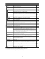
Item
Explanation
Torque boost
• Auto torque boost (For constant torque load) *1 to *4
• Manual torque boost: Torque boost value can be set between 0.0 and 20.0%. *1, *4
• Select application load with the function code. (Variable torque load or constant torque
load) *1, *4
Starting torque
(HD mode)
• 22 kW or below: 200% or higher, 30 kW or above: 180% or higher/reference frequency:
0.3 Hz *6
• 22 kW or below: 200% or higher, 30 kW or above: 180% or higher/reference frequency:
0.3 Hz, Base frequency 50 Hz *2
• Auto torque boost operation *1 to*4
Start/stop operation
Keypad:
Start and stop with
and
Start and stop with
/
Remarks
keys (Standard keypad)
and
keys (Optional multi-function keypad)
External signals (digital inputs): Forward (Reverse) rotation, stop command (capable of
3-wire operation), coast-to-stop command, external alarm, alarm reset, etc.
Link operation: Operation through RS-485 or field bus (option) communications
Switching operation command: Remote/local switching, link switching
Frequency setting
Keypad: Settable with
and
keys
External volume: Can be set with external frequency command potentiometer. (1 to 5 kΩ
1/2 W)
Analog input: 0 to ±10 V DC (±5 V DC)/ 0 to ±100% (terminals [12] and [V2]),
0 to +10 V DC (+5 V DC)/ 0 to +100% (terminals [12] and [V2])
: +4 to +20 mA DC/ 0 to 100% (terminal [C1])
"+1 to +5
VDC" can
be
adjusted
with bias
and
analog
input gain.
UP/DOWN operation:
Frequency can be increased or decreased while the digital input signal is ON.
Multi-frequency: Selectable from 16 different frequencies (step 0 to 15)
Control
Link operation: Frequency can be specified through RS-485. (Standard setting)
Frequency setting: Two types of frequency settings can be switched with an external signal
(digital input). Remote/local switching, link switching
Auxiliary frequency setting: Inputs at terminal [12], [C1] or [V2] can be added to the main
setting as auxiliary frequency settings.
Operation at a specified ratio: The ratio can be set by analog input signal.
Inverse operation : Switchable from "0 to +10 VDC/0 to 100%" to
"+10 to 0 VDC/0 to 100%" by external command.
: Switchable from "4 to +20 mA DC/0 to 100%" to
"+20 to 4 mA DC/0 to 100%" by external command.
Pulse train input (standard):
Pulse input = Terminal [X7], Rotational direction = general terminal
Complementary output: Max. 100 kHz, Open collector output: Max. 30 kHz
Pulse train input (option):
PG interface option CW/CCW pulse, pulse + rotational direction
Complementary output: Max. 100 kHz, Open collector output: Max. 25 kHz
Acceleration/
deceleration time
Setting range: Between 0.00 and 6000 s
Switching: The four types of acceleration/deceleration time can be set or selected
individually (switchable during operation).
Acceleration/deceleration pattern: Linear acceleration/deceleration, S-shape
acceleration/deceleration (weak, free (strong)), curvilinear acceleration/deceleration
(acceleration/deceleration max. capacity of constant output)
Acceleration/deceleration pattern: Linear acceleration/deceleration, S-shape
acceleration/deceleration (weak, free, (strong)), curvilinear acceleration/deceleration
(acceleration/deceleration maximum capacity of constant output)
Deceleration mode (coast-to-stop):
Shutoff of the run command lets the motor coast to a stop.
Forcible stop deceleration time: Deceleration stop by the forcible stop STOP.
Auto-tuning by shortest acceleration/deceleration mode and optimal acceleration/
deceleration mode
*1
*2
*3
*4
*6
*8
Available under V/f control.
Available under dynamic torque vector control.
Available when the slip compensation is made active under V/f control.
Available under V/f control with speed sensor. (PG option required)
Available under vector control without speed sensor.
Not available in the initial version of inverters.
2-4
*8
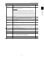
2.2 Common Specifications
Item
Frequency limiter
Explanation
Remarks
• Specifies the high and low limits in Hz.
• Bias of set frequency and PID command can be independently set
(setting range: 0 to ±100%).
Analog input
• Gain
SPECIFICATIONS
Bias frequency
Chap. 2
(Upper limit and lower • It is possible to choose the operation done when the set frequency drops below the
lower limit from between continuous operation at lower limit frequency and operation
limit frequencies)
stop.
: Set in the range from 0 to 200%
• Off-set : Set in the range from -5.0 to +5.0%
• Filter : Set in the range from 0.00s to 5.00 s
Jump frequency
• Three operation points and their common jump width (0 to 30.0 Hz) can be set.
Jogging operation
• Operation with
key (standard keypad),
digital contact input FWD or REV
Auto-restart after
momentary power
failure
• Trip at power failure: The inverter trips immediately after power failure.
or
key (multi-function keypad), or
(Exclusive acceleration/deceleration time setting, exclusive frequency setting)
• Trip at power recovery: Coast-to-stop at power failure and trip at power recovery
• Deceleration stop: Deceleration stop at power failure, and trip after stoppage
• Continue to run: Operation is continued using the load inertia energy.
• Start at the frequency selected before momentary power failure: Coast-to-stop at power
failure and start after power recovery at the frequency selected before momentary stop.
*1 to*3
Control
• Start at starting frequency: Coast-to-stop at power failure and start at the starting
frequency after power recovery. *1 to *3
Hardware current
limiter
Limits the current by hardware to prevent an overcurrent trip from being caused by fast
load variation or momentary power failure, which cannot be covered by the software
current limiter. This limiter can be canceled.
Operation by
commercial power
supply
• With commercial power selection command, the inverter outputs 50/60 Hz (SW50,
SW60). *1 to*3
Slip compensation
Compensates for decrease in speed according to the load. *1 to *3
Droop control
Decreases the speed according to the load torque.
Torque limit
• Switchable between 1st and 2nd torque limit values
• The inverter has the commercial power supply selection sequence.
• Torque limit, torque current limit, and power limit are set for each quadrant. *6, *7
• Analog torque limit input
Software current
limiter
Automatically reduces the frequency so that the output current becomes lower than the
preset operation level. *1 to *5
PID Control
• PID processor for process control/dancer control
• Normal operation/inverse operation
• Low liquid level stop function (pressurized operation possible before low liquid level
stop)
• PID command: Keypad, analog input (from terminals [12], [C1] and [V2]), RS-485
communication
• PID feedback value (from terminals [12], [C1] and [V2])
• Alarm output (absolute value alarm, deviation alarm)
• PID output limiter
• Integration reset/hold
• Anti-reset wind-up function
Auto search for idling
motor speed
The inverter automatically searches for the idling motor speed to be harmonized and starts
to drive it without stopping it.
(Motor electric constant needs tuning: Offline tuning) *1 to * 3 and *6
*1
*2
*3
*4
*5
*6
*7
*8
Available under V/f control.
Available under dynamic torque vector control.
Available when the slip compensation is made active under V/f control.
Available under V/f control with speed sensor. (PG option required)
Available under dynamic torque vector control with speed sensor. (PG option required)
Available under vector control without speed sensor.
Available under vector control with speed sensor. (PG option required)
Not available in the initial version of inverters.
2-5
*8
Item
Automatic
deceleration
Explanation
Remarks
• If the DC link bus voltage or calculated torque exceeds the automatic deceleration level
during deceleration, the inverter automatically prolongs the deceleration time to avoid
overvoltage trip.
(It is possible to select forcible deceleration actuated when the deceleration time
becomes three times longer.)
• If the calculated torque exceeds automatic deceleration level during constant speed
operation, the inverter avoids overvoltage trip by increasing the frequency.
Deceleration
characteristic
(improved braking
capacity)
The motor loss is increased during deceleration to reduce the regenerative energy in the
inverter to avoid overvoltage trip. *1, *4
Auto energy saving
operation
The output voltage is controlled to minimize the total sum of the motor loss and inverter
loss at a constant speed.
Control
(With digital input signal, auto energy saving mode can be turned ON or OFF by an
external device.)
Overload prevention
control
If the surrounding temperature or IGBT joint temperature increases due to overload, the
inverter lowers the output frequency to avoid overload.
Auto-tuning (offline)
Tuning the motor while the motor is stopped or running, for setting up motor parameters.
Auto-tuning (online)
Tuning for compensating the temperature change in motor parameters.
Cooling fan ON/OFF
control
• Detects inverter internal temperature and stops cooling fan when the temperature is low.
2nd to 4th motor
settings
• Switchable among the four motors
*8
*8
• The fan control signal can be output to an external device.
• Code data for four kinds of specific functions can be switched (even during operation).
It is possible to set the base frequency, rated current, torque boost, and electronic
thermal slip compensation as the data for 1st to 4th motors.
Universal DI
The status of external digital signal connected with the universal digital input terminal is
transferred to the host controller.
Universal DO
Digital command signal from the host controller is output to the universal digital output
terminal.
Universal AO
The analog command signal from the host controller is output to the analog output
terminal.
*8
Overload stop function When the torque or the current exceeds the specified level, the inverter decelerates the
motor to a stop or allows the motor to coast to a stop. When the motor is interrupted by a
mechanical stop, the inverter controls the current to secure the holding torque. *1 to *5
Speed control
• Notch filter for vibration control, vibration suppressing observer. *7
*8
• Estimates the GD2 value applied to the motor shaft from the load, and automatically
controls the ASR system constant. *6 and *7
Preliminary excitation
Excitation is carried out to create the motor flux before starting the motor. *6 and*7
Zero speed control
The motor speed is held to zero by forcibly zeroing the speed command. *7
Servo lock
Stops the motor and holds the motor in the stopped position. *7
*8
Torque control *6, *7
• Analog torque command input
*8
• Speed limit function is provided to prevent the motor from becoming out of control.
*1
*2
*3
*4
*5
*6
*7
*8
Rotational direction
control
Select either of reverse or forward rotation prevention.
Dew condensation
prevention
When the motor is stopped, current is automatically supplied to the motor to keep the
motor warm and avoid condensation.
Customized logic
interface
Available in 10 steps with the functions of 2-input, 1-output, logical operation, and timer
function
Available under V/f control.
Available under dynamic torque vector control.
Available when the slip compensation is made active under V/f control.
Available under V/f control with speed sensor. (PG option required)
Available under dynamic torque vector control with speed sensor. (PG option required)
Available under vector control without speed sensor.
Available under vector control with speed sensor (PG option required)
Not available in the initial version of inverters.
2-6
*8
2.2 Common Specifications
Running/Stopping
Speed monitor (reference frequency, output frequency, motor speed, load shaft speed, line
speed, and speed indication with percent), output current [A], output voltage [V],
calculated torque [%], input power [kW], PID command value, PID feedback value, PID
output, load factor [%], motor output [kW], torque current [%] *6 *7, magnetic flux
command [%]*6 *7, analog input and input watt-hour
Life early warning
• The life early warning of the main circuit capacitors, capacitors on the PC boards and
the cooling fan can be displayed.
Remarks
SPECIFICATIONS
Explanation
Chap. 2
Item
Display
• An external output is issued in a transistor output signal.
• Surrounding temperature: 40°C, Load rate: inverter rated current 100% (LD mode:
80%)
Cumulative run time
• Displays the inverter cumulative run time, input watt-hour, cumulative motor run time,
and the number of startups (of each motor).
• Outputs the warning when the maintenance time or the number of start times has
exceeded the preset.
Trip mode
Displays the cause of trip by codes.
Light-alarm
Shows the light-alarm display l-al.
Running or trip mode
• Trip history: Saves and displays the cause of the last four trips (with a code).
• Saves and displays the detailed operation status data of the last four trips.
Overcurrent protection The inverter is stopped for protection against overcurrent.
Short-circuit
protection
The inverter is stopped for protection against overcurrent caused by a short circuit in the
output circuit.
Ground fault
protection
The inverter is stopped for protection against overcurrent caused by a ground fault in the
output circuit. (200 V 22 kW, 400V 22 kW or below)
Detecting zero-phase current of output current, the inverter is stopped for protection
against overcurrent caused by a ground fault in the output circuit. (200 V 30 kW, 400 V
30 kW or above)
ef
Overvoltage
protection
An excessive voltage (200 V class series: 400 VDC, 400 V class series: 800 VDC) in the 0u1
DC link circuit is detected and the inverter is stopped. If an excessive voltage is applied by 0u2
mistake, the protection cannot be guaranteed.
0u3
Undervoltage
protection
The voltage drop (200 V class series: 200 VDC, 400 V class series: 400 VDC) in the DC
link circuit is detected to stop the inverter.
However, the alarm will not be issued when the re-starting after instantaneous stop is
selected.
Protection
0c1
0c2
0c3
Input phase loss
protection
• The input phase loss is detected to shut off the inverter output. This function protects
the inverter.
lu
lin
• When the load is small or a DC reactor is connected, a phase loss may not be detected.
Output phase loss
protection
Overheat protection
Detects breaks in inverter output wining during running, to shut off the inverter output.
Stop the inverter output detecting excess cooling fan temperature in case of a cooling fan
fault or overload
Stop the inverter output detecting a fault of inner agitating fan. (200 V 45 kW, 400 V 75 kW
or above)
Stop the inverter output detecting inner temperature of the inverter unit for a cooling fan
fault or overload.
0pl
0h1
0h3
Protect the braking resistor from over heat by setting the braking resistor electronic thermal
dbh
function.
Overload protection
Stops the inverter output upon detection of the abnormal heat sink temperature and
switching element temperature calculated with the output current.
0lu
External alarm input
With the digital input signal THR opened, the inverter is stopped with an alarm.
0h2
Fuse blown
Stop the inverter output detecting the fuse breaking of the main circuit in the inverter.
(200 V 75 kW, 400 V 90 kW or above)
fus
Charge circuit fault
Stop the inverter output detecting the charge circuit abnormality in the inverter.
(200 V 37 kW, 400 V 75 kW or above)
pbf
*6 Available under vector control without speed sensor.
*7 Available under vector control with speed sensor. (PG option required)
2-7
Item
Explanation
Braking transistor
broken
Stop the inverter detecting the brake transistor abnormality.
(DB transistor built-in type only
Overspeed protection
*4 to *7
Stop the inverter when the detected speed exceeds 120% of maximum output frequency.
PG wire break *4 *5 *7 Stop the inverter detecting the PG braking.
Protection
Motor protection
Electronic thermal The inverter is stopped with an electronic thermal function set to protect the motor.
Protects the general-purpose motor inverter over all frequency range. (The running level
and thermal time constant (0.5 to 75.0 min) can be set.)
PTC thermistor
NTC thermistor
dba
0s
pg
0l1 to
0l4
A PTC thermistor input stops the inverter to protect the motor. Connect a PTC thermistor
between terminals [V2] and [11] and set the switch on control print board and the function
code.
0h4
The NTC thermistor detects a motor temperature. Connect a NTC thermistor between
terminals [V2] and [11] and set the switch on control print board and the function code.
NTC thermistor
breaking
Stop the inverter output detecting the built-in motor NTC breaking.
Overload early
warning
Warning signal is output at the predetermined level before stopping the inverter with
electronic thermal function.
nrb
Memory error
Data is checked upon power-on and data writing to detect any fault in the memory and to
stop the inverter if any.
Keypad
communications error
The keypad is used to detect a communication fault between the keypad and inverter main
er2
body during operation and to stop the inverter.
er1
CPU error
Stop the invert detecting a CPU error or LSI error caused by noise.
er3
Option
communications error
When each option is used, a fault of communication with the inverter main body is
detected to stop the inverter.
er4
Option error
When each option is used, the option detects a fault to stop the inverter.
er5
Operation protection
STOP key priority: Pressing the
key on the keypad or entering the digital input signal
will forcibly decelerate and stop the motor even if the operation command through signal
input or communication is selected. er6 will be displayed after the stop.
Start check: If the running command is being ordered when switching the running
command method from power-on, alarm reset, or the linked operation, the operation starts
suddenly. This function bans running and displays er6.
Tuning error
*4
*5
*6
*7
Remarks
er6
Stop the inverter output when tuning failure, interruption, or any fault as a result of tuning
er7
is detected during tuning for motor constant.
RS-485
communications error
(port 1)
When the connection port of the keypad connected via RS-485 communication port to
detect a communication error, the inverter is stopped and displays an error.
Speed mismatch or
excessive speed
deviation *4 to *7
Stop the inverter output when the speed deviation excesses the specified value (difference
ere
between speed command and feedback).
Data save error upon
undervoltage
When the undervoltage protection function works, an alarm is displayed if the data is not
properly saved.
RS-485
communications error
(port 2)
Stop the inverter output detecting the communication error between the inverter main unit
erp
and a mate when the RS-485 connection port of the touch panel is used to configure the
network.
Hardware error
Stop the inverter output detecting the LSI abnormality of the print board for power supply
erh
which is mainly caused by noise.
er8
erf
err
Mock alarm
Simulated alarm is output by the keypad operation.
PID feedback wire
break
Stop the inverter output detecting a breaking when the input current is allocated to the PID
cof
control feedback. (Select valid/invalid.)
Available under V/f control with speed sensor. (PG option required)
Available under dynamic torque vector control with speed sensor. (PG option required)
Available under vector control without speed sensor.
Available under vector control with speed sensor. (PG option required)
2-8
2.2 Common Specifications
Item
Explanation
• The relay signal is output when the inverter stops upon an alarm.
(for any fault)
•
Light-alarm (warning)
The "light-alarm" display is indicated when alarm or warning matters set as minor troubles
occurred. The operation is continued.
key or digital input signal RST is used to reset the alarm stop state.
Stall prevention
Operates when the inverter output goes beyond the instantaneous overcurrent limiting
level, and avoids tripping, during acceleration and constant speed operation.
Retry function
When the motor is tripped and stopped, this function automatically resets the tripping state
and restarts operation.
Surge protection
The inverter is protected against surge voltage intruding between the main circuit power
line and ground.
Command loss
detection
A loss (breaking, etc.) of the frequency command is detected to output an alarm and the
operation is continued at the preset frequency (set at a ratio to the frequency before
detection).
Momentary power
failure protection
• A protective function (inverter stoppage) is activated upon a momentary power failure
for 15 ms or longer.
Environment
• If restart upon momentary power failure is selected, the inverter restarts upon recovery
of the voltage within the set time.
Installation location
Shall be free from corrosive gases, flammable gases, oil mist, dusts, and direct sunlight.
(Pollution degree 2 (IEC60664-1)). Indoor use only.
Surrounding
temperature
-10 to +50°C (-10 to +40°C when installed side-by-side without clearance (22 kW or
below))
Relative humidity
5 to 95% RH (without condensation)
Altitude
Lower than 1,000 m
Vibration
200 V 55 kW, 400 V 75 kW or below
3 mm: 2 to less than 9 Hz, 9.8m/s2: 9 to less than 20 Hz
2 m/ s2: 20 to less than 55 Hz, 1m/ s2:55 to less than 200 Hz
Storage temperature
-25 to +65°C
Storage humidity
5 to 95% RH (without condensation)
2-9
SPECIFICATIONS
Protection
Light alarm object
Heat sink overheat (0h1 ), External alarm(0h2 ), Inverter internal overheat (0h3 ),
Motor protection (0h4 ), Braking resistor overheat (dbh ), Overload of motor (0l1 to
0l4 ), Keypad communications error (er2), Option communications error (er4 ),
l-al
Option error (er5 ), RS-485 communications error (port 1) (er8 ), Speed mismatch or
excessive speed deviation (ere ), RS-485 communications error (port 2) (erp ), DC fan
locked, Motor overload early warning, Heat sink overheat early warning, Lifetime alarm
(DC link bus capacitor, electrolytic capacitors on printed circuit boards or cooling fans),
PTC thermistor activated (pTc), Inverter life (Cumulative run time), Inverter life (number
of startups)
Chap. 2
Alarm relay output
Remarks
2.3 Terminal Specifications
2.3.1
Terminal functions
Classification
Main circuit and analog input terminals
Symbol
Name
Main circuit
L1/R, L2/S, Main circuit
L3/T
power inputs
Connect the three-phase input power lines.
U, V, W
Inverter outputs Connect a three-phase motor.
R0, T0
Auxiliary power For a backup of the control circuit power supply, connect AC power
input for the
lines same as that of the main power input.
control circuit
P1, P(+)
DC reactor
connection
P(+), DB
Braking resistor Connect the braking resistor (option).
P(+), N(-)
DC link bus
R1, T1
Auxiliary power Normally, no need to use these terminals. Use these terminals for
input for the fans an auxiliary power input of the fans in a power system using a
power regenerative PWM converter (RHC series).
G
[13]
[12]
Analog input
Functions
Connect a DC reactor (DCR) for correcting power factor.
• HD-mode inverters: A DCR is provided as option for 0.4 to 55
kW, and as standard for 75 kW or above.
• LD-mode inverters: A DCR is provided as option for 5.5 to 45
kW, and as standard for 55 kW or above.
Connect a DC link bus of other inverter(s). A high power-factor,
regenerative PWM converter is also connectable to these terminals.
Grounding for
inverter and
motor
Grounding terminals for the inverter’s chassis (or case) and motor.
Earth one of the terminals and connect the grounding terminal of the
motor. Inverters provide a pair of grounding terminals that function
equivalently.
Power supply
for the
potentiometer
Power supply (+10 VDC) for frequency command potentiometer
(Potentiometer: 1 to 5kΩ)
Analog setting
voltage input
(1) The frequency is commanded according to the external analog
voltage input.
• 0 to ±10 VDC/0 to ±100% (Normal operation)
• +10 to 0 VDC/0 to 100% (Inverse operation)
The potentiometer of 1/2 W rating or more should be connected.
(2) In addition to frequency setting, PID command, PID feedback
signal, auxiliary frequency command setting, ratio setting,
torque limiter level setting, or analog input monitor can be
assigned to this terminal.
(3) Hardware specifications
• Input impedance: 22kΩ
• The maximum input is ±15 VDC, however, the voltage
higher than ±10 VDC is handled as ±10 VDC.
• Inputting a bipolar analog voltage (0 to ±10 VDC) to
terminal [12] requires setting function code C35 to "0."
2-10
Symbol
[C1]
Functions
Analog setting
current input
(C1 function)
(1) The frequency is commanded according to the external analog
current input.
• 4 to 20 mA DC/0 to 100% (Normal operation)
• 20 to 4 mA DC/0 to 100 % (Inverse operation)
(2) In addition to frequency setting, PID command, PID feedback
signal, auxiliary frequency command setting, ratio setting,
torque limiter level setting, or analog input monitor can be
assigned to this terminal.
(3) Hardware specifications
• Input impedance: 250Ω
• The maximum input is +30 mA DC, however, the current
larger than +20 mA DC is handled as +20 mA DC.
[V2]
Analog setting
voltage input
(V2 function)
(1) The frequency is commanded according to the external analog
voltage input.
• 0 to ±10 VDC/0 to ±100 % (Normal operation)
• +10 to 0 VDC/0 to 100% (Inverse operation)
(2) In addition to frequency setting, PID command, PID feedback
signal, auxiliary frequency command setting, ratio setting,
torque limiter level setting, or analog input monitor can be
assigned to this terminal.
Analog input
(3) Hardware specifications
• Input impedance: 22kΩ
• The maximum input is ±15 VDC, however, the voltage
higher than ±10 VDC is handled as ±10 VDC.
• Inputting a bipolar analog voltage (0 to ±10 VDC) to
terminal [V2] requires setting function code C45 to "0."
PTC/NTC
thermistor input
(PTC/NTC
function)
(1) Connects PTC (Positive Temperature Coefficient)/NTC
(Negative Temperature Coefficient) thermistor for motor
protection. Ensure that the slide switch SW5 on the control
PCB is turned to the PTC/NTC position (refer to "Setting up
the slide switches" on page 2-20).
The figure shown at the right illustrates the internal circuit
diagram where SW5 (switching the input of terminal [V2]
between V2 and PTC/NTC) is turned to the PTC/NTC
position. For details on SW5, refer to "Setting up the slide
switches" on page 2-20. In this case, you must change data of
the function code H26.
[13]
Resistor
27kΩ
[V2]
PTC/NTC
thermistor
SW5
V2
<Control circuit>
DC +10 V
(Operation level)
H27
Compartor
PTC/NTC
[11]
External
alarm
H26
0V
Figure 2.1 Internal Circuit Diagram
(SW5 Selecting PTC/NTC)
[11]
Analog common Common for analog input/output signals ([13], [12], [C1], [V2]
and [FMA]).
Isolated from terminals [CM]s and [CMY].
2-11
SPECIFICATIONS
Name
Chap. 2
Classification
2.3 Terminal Specifications
Classification
Symbol
Name
-
-
Analog input
-
-
Functions
Related
function
codes
Since low level analog signals are handled, these signals are especially susceptible
to the external noise effects. Route the wiring as short as possible (within 20 m)
and use shielded wires. In principle, ground the shielded sheath of wires; if effects
of external inductive noises are considerable, connection to terminal [11] may be
effective. As shown in Figure 2.2, be sure to ground the single end of the shield to
enhance the shield effect.
Use a twin-contact relay for low level signals if the relay is used in the control
circuit. Do not connect the relay's contact to terminal [11].
When the inverter is connected to an external device outputting the analog signal,
the external device may malfunction due to electric noise generated by the
inverter. If this happens, according to the circumstances, connect a ferrite core (a
toroidal core or equivalent) to the device outputting the analog signal or connect a
capacitor having the good cut-off characteristics for high frequency between
control signal wires as shown in Figure 2.3.
Do not apply a voltage of +7.5 VDC or higher to terminal [C1]. Doing so could
damage the internal control circuit.
Figure 2.2 Connection of Shielded Wire
2-12
Figure 2.3 Example of Electric Noise Reduction
2.3 Terminal Specifications
Symbol
Functions
[X1]
Digital input 1
[X2]
Digital input 2
[X3]
Digital input 3
[X4]
Digital input 4
[X5]
Digital input 5
[X6]
Digital input 6
[X7]
Digital input 7
[X8]
Digital input 8
[X9]
Digital input 9
[FWD]
Run forward
command
[REV]
Run reverse
command
(1) Various signals such as "Coast to a stop," "Enable external
alarm trip," and "Select multi-frequency" can be assigned to
terminals [X1] to [X9], [FWD] and [REV] by setting function
codes E01 to E09, E98, and E99. For details, refer to Chapter
5 "FUNCTION CODES."
(2) Input mode, i.e. SINK/SOURCE, is changeable by using the
slide switch SW1. (Refer to "Setting up the slide switches" on
page 2-20.)
(3) Switches the logic value (1/0) for ON/OFF of the terminals
[X1] to [X9], [FWD], or [REV]. If the logic value for ON of
the terminal [X1] is 1 in the normal logic system, for example,
OFF is 1 in the negative logic system and vice versa.
(4) Digital input terminal [X7] can be defined as a pulse train
input terminal with the function codes.
Maximum wiring length 20 m
Maximum input pulse
30 kHz: When connected to a pulse generator with open
collector transistor output
(Needs a pull-up or pull-down resistor. See notes on
page 2-15.)
100 kHz: When connected to a pulse generator with
complementary transistor output
For the settings of the function codes, refer to Chapter 5
"FUNCTION CODES."
Digital input
(Digital input circuit specifications)
Figure 2.4 Digital Input Circuit
Item
Operating
ON level
voltage
OFF level
(SINK)
Operating
ON level
voltage
OFF level
(SOURCE)
Operating current at
ON
(Input voltage is at 0 V)
(For [X7])
Allowable leakage current
at OFF
2-13
Min.
0V
Max.
2V
22 V
27 V
22 V
27 V
0V
2V
2.5 mA
5 mA
(9.7 mA)
(16 mA)
−
0.5 mA
SPECIFICATIONS
Name
Chap. 2
Classification
Digital Input Terminals
Classification
Symbol
Name
Functions
[PLC]
PLC signal
power
(1) Connects to PLC output signal power supply.
Rated voltage: +24 VDC (Allowable range: +22 to +27
VDC), Maximum 100 mA DC
(2) This terminal also supplies a power to the load connected to
the transistor output terminals [Y1] and [Y2]. Refer to
"Transistor output" described later in this table for more.
[CM]
Digital input
common
Two common terminals for digital input signals
These terminals are electrically isolated from the terminals [11]s
and [CMY].
Using a relay contact to turn [X1] to [X9], [FWD], or [REV] ON or OFF
Figure 2.5 shows two examples of a circuit that uses a relay contact to turn control
signal input [X1] to [X9], [FWD], or [REV] ON or OFF. In circuit (a), the slide
switch SW1 has been turned to SINK, whereas in circuit (b) it has been turned to
SOURCE.
Note: To configure this kind of circuit, use a highly reliable relay.
(Recommended product: Fuji control relay Model HH54PW.)
<Control circuit>
SOURCE
[X1] to [X9],
[FWD], [REV]
Photocoupler
[CM]
SINK
+24 VDC
[PLC]
SINK
[PLC]
+24 VDC
Digital input
<Control circuit>
SOURCE
[X1] to [X9],
[FWD], [REV]
Photocoupler
[CM]
(a) With the switch turned to SINK
(b) With the switch turned to SOURCE
Figure 2.5 Circuit Configuration Using a Relay Contact
Using a programmable logic controller (PLC) to turn [X1] to [X9], [FWD], or
[REV] ON or OFF
Figure 2.6 shows two examples of a circuit that uses a programmable logic controller
(PLC) to turn control signal input [X1] to [X9], [FWD], or [REV] ON or OFF. In
circuit (a), the slide switch SW1 has been turned to SINK, whereas in circuit (b) it has
been turned to SOURCE.
In circuit (a) below, short-circuiting or opening the transistor's open collector circuit
in the PLC using an external power supply turns ON or OFF control signal [X1] to
[X9], [FWD], or [REV]. When using this type of circuit, observe the following:
- Connect the + node of the external power supply (which should be isolated from
the PLC's power) to terminal [PLC] of the inverter.
- Do not connect terminal [CM] of the inverter to the common terminal of the PLC.
2-14
Name
Programmable
logic controller
Functions
Programmable
logic controller
<Control circuit>
SINK
+24 VDC
PLC
SOURCE
[X1] to [X9],
[FWD], [REV]
Photocoupler
CM
SOURCE
[X1] to [X9],
[FWD], [REV]
Photocoupler
CM
(a) With the switch turned to SINK
Digital input
SINK
(b) With the switch turned to SOURCE
Figure 2.6 Circuit Configuration Using a PLC
For details about the slide switch setting, refer to "Setting up the slide switches" on page
2-20.)
For inputting a pulse train through the digital input terminal [X7]
• Inputting from a pulse generator with an open collector transistor output
Stray capacity on the wiring between the pulse generator and the inverter may disable
transmission of the pulse train. As a countermeasure against this problem, insert a
pull-up resistor between the open collector output signal (terminal [X7]) and the
power source terminal (terminal [PLC]) if the switch selects the SINK mode input;
insert a pull-down resistor between the output signal and the digital common
terminal (terminal [CM]) if the switch selects the SOURCE mode input.
A recommended pull-up/down resistor is 1kΩ 2 W. Check if the pulse train is
correctly transmitted because stray capacity is significantly affected by the wire
types and wiring conditions.
2-15
SPECIFICATIONS
PLC
<Control circuit>
+24 VDC
Symbol
Chap. 2
Classification
2.3 Terminal Specifications
Classification
Analog output, pulse output, transistor output, and relay output terminals
Symbol
Analog monitor
(FMA function)
Analog output
[FMA]
Name
Functions
The monitor signal for analog DC voltage (0 to +10 V) or analog
DC current (+4 to +20 mA) is output. You can select the output
form (VO/IO) by switching the slide switch SW4 on the control
PCB and changing data of the function code F29. You can select
one of the following signal functions with function code F31.
• Output frequency
• Output current
• Output voltage
• Output torque
• Load factor
• Input power
• PID feedback amount • Speed (PG feedback value)
• DC link bus voltage • Universal AO
• Motor output
• Calibration
• PID command
• PID output
* Input impedance of the external device: Min. 5kΩ (at 0 to 10
VDC output)
(While the terminal is outputting 0 to 10 VDC, it is capable of
driving up to two analog voltmeters with 10 kΩ impedance.)
* Input impedance of the external device: Max. 500Ω (at 4 to
20 mA DC output)
* Adjustable range of the gain: 0 to 300%
[11]
Analog common
Two common terminals for analog input and output signals.
These terminals are electrically isolated from terminals [CM]s
and [CMY].
[FMP]
Pulse monitor
(FMP function)
Pulse signal is output. You can also select one of the signal
functions listed in the above column for [FMA] using function
code F35.
* Input impedance of the external device: Min. 5kΩ
(While the terminal is outputting 0 to 10 VDC, it is capable of
driving up to two analog voltmeters with 10 kΩ impedance.)
* Pulse duty: Approx. 50%
Pulse rate: 25 to 6000 p/s (at full scale)
Pulse output
Voltage waveform
[CM]
Digital common
•
Pulse output waveform
•
FMP output circuit
Two common terminals for digital input and [FMP] output
signals.
These terminals are electrically isolated from other common
terminals, [11]s and [CMY].
These are the shared terminals with the digital input terminal
[CM]s.
2-16
Symbol
Name
Transistor
output 1
[Y2]
Transistor
output 2
[Y3]
Transistor
output 3
[Y4]
Transistor
output 4
(1) Various signals such as inverter running, speed/freq. arrival
and overload early warning can be assigned to any terminals,
[Y1] to [Y4] by setting function code E20 to E24. Refer to
Chapter 5 "FUNCTION CODES" for details.
(2) Switches the logic value (1/0) for ON/OFF of the terminals
between [Y1] to [Y4], and [CMY]. If the logic value for ON
between [Y1] to [Y4] and [CMY] is 1 in the normal logic
system, for example, OFF is 1 in the negative logic system
and vice versa.
(Transistor output circuit specifications)
<Control circuit>
Photocoupler
[Y1]
to
[Y4]
31 to 35 V
[CMY]
Voltage
Current
Transistor output
Figure 2.7 Transistor Output Circuit
Item
Operation
voltage
Max.
ON level
2V
OFF level
27 V
Maximum motor
current at ON
50 mA
Leakage current
at OFF
0.1 mA
Figure 2.8 shows examples of connection between the control
circuit and a PLC.
• When a transistor output drives a control relay,
connect a surge-absorbing diode across relay’s coil
terminals.
• When any equipment or device connected to the
transistor output needs to be supplied with DC power,
feed the power (+24 VDC: allowable range: +22 to
+27 VDC, 100 mA max.) through the [PLC] terminal.
Short-circuit between the terminals [CMY] and [CM]
in this case.
[CMY]
Transistor
output common
Common terminal for transistor output signals
This terminal is electrically isolated from terminals [CM]s and
[11]s.
2-17
SPECIFICATIONS
[Y1]
Functions
Chap. 2
Classification
2.3 Terminal Specifications
Classification
Symbol
Name
Related
function
codes
Functions
<Control circuit>
C0
Current
Photocoupler
[Y1]
to
[Y4]
31 to
35 V
Programmable
logic controller
[CMY]
Current
SINK input
[Y1]
to
[Y4]
31 to
35 V
+24 VDC
Photocoupler
<Control circuit>
Programmable
logic controller
+24 VDC
Transistor output
Connecting programmable logic controller (PLC) to terminal [Y1], [Y2], [Y3]
or [Y4]
Figure 2.8 shows two examples of circuit connection between the transistor output of
the inverter’s control circuit and a PLC. In example (a), the input circuit of the PLC
serves as a SINK for the control circuit output, whereas in example (b), it serves as a
SOURCE for the output.
[CMY]
SOURCE input
C0
(a) PLC serving as SINK
(b) PLC serving as SOURCE
Figure 2.8 Connecting PLC to Control Circuit
General
purpose relay
output
Relay output
[Y5A/C]
Contact rating: 250 VAC 0.3 A, cos φ = 0.3, 48 VDC, 0.5 A
(2) Switching of the normal/negative logic output is applicable to
the following two contact output modes: "Active ON"
(Terminals [Y5A] and [Y5C] are closed (excited) if the signal
is active.) and "Active OFF" (Terminals [Y5A] and [Y5C] are
opened (non-excited) if the signal is active while they are
normally closed.).
[30A/B/C]
Relay output
(1) A general-purpose relay contact output usable as well as the
function of the transistor output terminal [Y1], [Y2], [Y3] or
[Y4].
Alarm relay
output
(for any error)
(1) Outputs a contact signal (SPDT) when a protective function
has been activated to stop the motor.
Contact rating: 250 VAC, 0.3A, cos φ = 0.3, 48 VDC, 0.5A
(2) Any one of output signals assigned to terminals [Y1] to [Y4]
can also be assigned to this relay contact to use it for signal
output.
(3) Switching of the normal/negative logic output is applicable to
the following two contact output modes: "Active ON"
(Terminals[30A] and [30C] are closed (excited) if the signal is
active.) and "Active OFF" (Terminals [30A] and [30C] are
opened (non-excited) if the signal is active while they are
normally closed.).
2-18
2.3 Terminal Specifications
Name
Functions
DX+/DX/SD
RS-485
communications
port 2
(Terminals
on control PCB)
A communications port transmits data through the RS-485
multipoint protocol between the inverter and a personal computer
or other equipment such as a PLC.
(For setting of the terminating resistor, refer to "Setting up the
slide switches" on page 2-20)
RJ-45
connector
for the
keypad
RS-485
(1) Used to connect the inverter with the keypad. The inverter
communications
supplies the power to the keypad through the pins specified
port 1
below. The extension cable for remote operation also uses
(Standard RJ-45
wires connected to these pins for supplying the keypad
connector)
power.
Communication
(2) Remove the keypad from the standard RJ-45 connector and
connect the RS-485 communications cable to control the
inverter through the PC or PLC (Programmable Logic
Controller). For setting of the terminating resistor, refer to
"Setting up the slide switches" on page 2-20.
Figure 2.9 RJ-45 Connector and its Pin Assignment*
* Pins 1, 2, 7, and 8 are exclusively assigned to power lines
for the standard keypad and multi-function keypad, so do
not use those pins for any other equipment.
USB
connector
USB port
(On the keypad)
A USB port connector (Mini-B) that connects an inverter to a
personal computer. FRENIC Loader (software*) running on the
computer supports editing the function codes, transferring them to
the inverter, verifying them, test-running an inverter and
monitoring the inverter running status.
* FRENIC Loader is available as a free download from our
website at:
http://web1.fujielectric.co.jp/Kiki-Info-EN/User/guestlogin.asp
(Fuji Electric FA Components & Systems Co., Ltd. Technical
Information site)
On the Fuji website shown above, select "Technical
Information" | "Drive Control Equipment" | "Inverters" |
"Software libraries." Then download the "FRENIC-MEGA
Loader (setup version)," "Message Manager for
FRENIC-MEGA PC Loader," and "Loader Software for
FRENIC-MEGA Instruction Manual."
Before downloading, you are requested to register as a member
(free of charge).
•
Route the wiring of the control circuit terminals as far from the wiring of the main circuit
as possible. Otherwise electric noise may cause malfunctions.
•
Fix the control circuit wires with a cable tie inside the inverter to keep them away from the
live parts of the main circuit (such as the terminal block of the main circuit).
2-19
SPECIFICATIONS
Connector
Chap. 2
Classification
RS-485 communications port