1
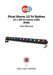
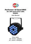
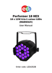
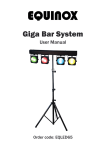
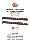
Heavy Duty DMX
Mirror Ball Rotator
with Safety Eye
User Manual
Order code: MIRR13
Safety advice
WARNING
FOR YOUR OWN SAFETY, PLEASE READ THIS USER MANUAL
CAREFULLY BEFORE YOUR INITIAL START-UP!
• Before your initial start-up, please make sure that there is no damage caused during transportation.
• Should there be any damage, consult your dealer and do not use the equipment.
• To maintain the equipment in good working condition and to ensure safe operation, it is necessary for the user to follow the safety instructions and warning notes written in this manual.
• Please note that damages caused by user modifications to this equipment are not subject to warranty.
CAUTION!
CAUTION!
TAKE CARE USING
THIS EQUIPMENT!
HIGH VOLTAGE-RISK
OF ELECTRIC SHOCK!!
KEEP THIS EQUIPMENT
AWAY FROM RAIN,
MOISTURE AND LIQUIDS
IMPORTANT:
The manufacturer will not accept liability for any resulting damages caused by the non-observance
of this manual or any unauthorised modification to the equipment.
• Never let the power cable come into contact with other cables.
Handle the power cable and all mains voltage connections with particular caution!
• Never remove warning or informative labels from the unit.
• Do not open the equipment and do not modify the unit.
• Do not connect this equipment to a dimmer pack.
• Do not switch the equipment on and off in short intervals, as this
will reduce the system’s life.
• Only use the equipment indoors.
• Do not expose to flammable sources, liquids or gases.
• Always disconnect the power from the mains when equipment is not in use or before cleaning! Only handle the
power-cable by the plug. Never pull out the plug by pulling the
power-cable.
• Make sure that the available voltage is 240V AC~50Hz.
• Make sure that the power cable is never crimped or damaged. Check the equipment and the power cable periodically.
• If the equipment is dropped or damaged, disconnect the mains
power supply immediately and have a qualified engineer inspect
the equipment before operating again.
• If the equipment has been exposed to drastic temperature fluctuation (e.g. after transportation), do not connect power or switch it on immediately. The arising condensation might damage the equipment.
Leave the equipment switched off until it has reached room
temperature.
• If your product fails to function correctly, stop use immediately.
Pack the unit securely (preferably in the original packing material), and return it to your Pro Light dealer
for service.
• Only use fuses of same type and rating.
• Repairs, servicing and power connection must only be carried out by a qualified technician. THIS UNIT CONTAINS NO
USER SERVICEABLE PARTS.
• WARRANTY: One year from date of purchase.
OPERATING DETERMINATIONS
If this equipment is operated in any other way, than those described in this manual, the product may suffer damage and the warranty becomes void. Incorrect operation may lead to danger e.g: short-circuit, burns and electric shocks etc.
Do not endanger your own safety and the safety of others!
Incorrect installation or use can cause serious damage to people and/or property.
This device is a mirror ball motor for turning mirror balls. The maximum load of the installation eyelet must never be exceeded. The safety eyelet must never be used for loads. When choosing the installation-spot, please make sure that the device is not exposed to extreme heat, moisture or dust.
There should not be any cables lying around. You endanger your own and the safety of others! This device must never be operated or stockpiled in surroundings where water, rain, moisture or fog may harm the device.
Moisture or very high humidity can reduce the electrical insulation and lead to mortal electrical shocks.
The ambient temperature must always be between -5°C and +45°C. Keep away from direct insulation (particularly in cars)
and heaters. The relative humidity must not exceed 50 % with an ambient temperature of 45°C. Never use the device during
thunderstorms. Over voltage could destroy the device. Always disconnect the device during thunderstorms. Make sure that the area below the installation place is blocked when rigging, derigging or servicing the fixture.
www.prolight.co.uk
DMX Mirror Ball Rotator User Manual
2
Product overview & technical specifications
Heavy Duty DMX Mirror Ball Rotator
Suitable for driving mirror balls up to a maximum weight of 40kg, this weight corresponds with a diameter of
120cm for our Equinox mirror balls. (The max. load is always the mirror ball weight including the mirror ball chain,
the safety chain and the fixation material.)
This rotator can be operated in stand alone mode, via a DMX interface and is programable via DIP switches, (DMX512 control is possible via most 1 channel DMX controller) and has three functions: Rotation direction, rotation speed and master/slave.
For professional use in pubs, clubs and in a variety of other environments where the EN DIN 15560 norms have to be considered.
•Rugged construction with steel housing for long operation
•Large motor axle for high stability
•Additional attachment eyelet for secondary attachment of the load
•Complies with the safety norm EN 292
Specifications
01
02
07
03
Power supply
240V, 50Hz
Power consumption
16W
Max. load BGV C1 (12:1 safety factor)
40kg
Max. diameter of mirror ball
120cm
Rotation speed
up to 5 RPM
Dimensions
105 x 289 x 240mm
Weight
6.15kg
Order code
MIRR13
04
08
05
06
09
01 - Mirror ball motor
02 - Motor axle
03 - Screw-on chain link
04 - Mirror ball chain
05 - Installation eyelet
www.prolight.co.uk
06 - Mirror ball
07 - Safety eyelet
08 - Safety chain
09 - Safety eyelet
In the box: 1 x rotator &
1 x user manual
DMX Mirror Ball Rotator User Manual
3
Installation
DANGER TO LIFE!
PLEASE CONSIDER THE EN 60598-2-17 AND THE RESPECTIVE NATIONAL
NORMS DURING THE INSTALLATION. THE INSTALLATION MUST ONLY BE
CARRIED OUT BY AN AUTHORISED DEALER!
The motor must only be installed in an absolutely horizontal position at a vibration-free, oscillation-free and fire-resistant
location. By using a water-level, make sure that the motor is installed absolutely horizontally and that the motor axle points
exactly to the bottom.
If the motor and the mirror ball are to be operated above persons, additional risks arise. A hazard analysis based on the location and application must be performed in order to ensure dimensioning and measures for a safe operation. Both the motor and the mirror ball meet the professional association safety regulations regarding safety and operation. The installation of the mirror ball has to be built and constructed in a way that it can hold 10 times the weight for 1 hour without any harming deformation.
The installation must always be secured with a secondary safety attachment. This secondary safety attachment must be constructed in a way that no part of the installation can fall down if the main attachment fails. When rigging, derigging or servicing the fixture staying in the area below the installation place, on bridges, under high working places and other endangered areas is forbidden. The operator has to make sure that safety-relating and machine-technical installations are approved by an expert before taking into operation for the first time and after changes before taking into operation another time.
The operator has to make sure that safety-relating and machine-technical installations are approved by an expert after every four year in the course of an acceptance test. The operator has to make sure that safety-relating and machine-technical installations are approved by a skilled person once a year.
Attachment:
The rotary motor should ideally be installed outside areas where persons may walk by or be seated. IMPORTANT! OVERHEAD RIGGING REQUIRES EXTENSIVE EXPERIENCE, including (but not limited to) calculating working load limits, installation material being used, and periodic safety inspection of all installation material and the mirror ball.
If you lack these qualifications, do not attempt the installation yourself, but instead use a professional structural rigger.
Improper installation can result in bodily injury and/or damage to property.
The motor and the mirror ball have to be installed out of the reach of people. If the motor shall be lowered from the ceiling or high joists, professional trussing systems have to be used. The motor must never be fixed swinging freely in the room. Caution: Mirror balls may cause severe injuries when crashing down! If you have doubts concerning the safety of a possible installation, do NOT install the motor! Before attaching the device, make sure that the installation area can hold a minimum point load of 10 times the device’s load (e.g. maximum load 3kg - point load 30kg). The mirror ball motor must always be installed via all fixation holes. Do only use appropriate screws and make sure that the screws are properly connected with the ground. The durability of the installation depends very much on the material used at the installation area (building material) such as wood, concrete, gas concrete, brick etc. This is why the fixing material must be chosen to suit the wall material.
Always ask a specialist for the correct plug/screw combination indicating the maximum load and the building material.
www.prolight.co.uk
DMX Mirror Ball Rotator User Manual
4
Installation & maintenance
The installation material must never include abrading material
eg steel cables in order to avoid material wearing.
The length of the chain must never exceed 100cm. Install the mirror ball chain with the screw-on chain link at the installation eyelet of the mirror ball and tighten the fixation screw. Insert the fourth chain link of the mirror ball chain with the mirror ball in the screw-on chain link and tighten the fixation screw. For overhead use, always install a safety chain on the mirror ball that can hold at least 12 times the weight of the installation. The safety chain must be slightly longer than the mirror ball chain so that the safety chain will always be tension-free. Pull the safety chain through the safety eyelet of the mirror ball and in the safety eyelet of the motor. The maximum drop distance must never exceed 20cm. A safety chain which already held the strain of a crash or which is defective must not be used again. There must never hang a mirror ball or other load at the safety eyelet. Loads must only be hanged at the quick link of the installation eyelet at the motor axle. If a mirror ball hangs for any reason at the safety eyelet, the motor must be taken out of operation immediately and the mirror ball must be uninstalled. The whole installation has to be checked for defects by an expert. Make sure that the rotation of the mirror ball is never slowed down or stopped by decoration material etc. Make sure that no side forces can impact on the installation. Make sure that the mirror ball cannot be moved by air streams. The mirror ball and the motor must be installed and operated absolutely swivel free. Please check in regular intervals, if the installation material (e. g. key ring, shackles or screw-on chain links) or chain links have been deformed. Uninstall the mirror ball immediately in such a case.
Cleaning & maintenance:
The operator has to make sure that safety-relating and machine-technical installations are inspected by an expert after every four years in the course of an acceptance test. The operator has to make sure that safety-relating and machine-technical installations are inspected by a skilled person once a year.
The following points have to be considered during the inspection: 1 - All screws used for installing the devices or parts of the device have to be tightly connected and must not be corroded. 2 - There must not be any deformations on housings, fixations and installation spots (ceiling, suspension, trussing). 3 - Mechanically moved parts like axles, eyes and others must not show any traces of wearing (e.g. material abrading or damages) and must not rotate with unbalances. 4 - The electric power supply cables must not show any damages, material fatigue (e.g. porous cables) or sediments. Further instructions depending on the installation spot and usage have to be adhered by a skilled installer and any safety
problems have to be removed.
DANGER TO LIFE!
DISCONNECT FROM MAINS BEFORE STARTING MAINTENANCE OPERATION.
We recommend a frequent cleaning of the device. Please use a soft lint-free and moistened cloth. Never use alcohol or
solvents! There are no serviceable parts inside the device. Maintenance and service operations are only to be carried out by
authorized dealers. If the fuse interrupts, please reset the breaker. Should you need any spare parts, please use genuine parts. If the power supply cable of this device will be damaged, it has
to be replaced by authorized dealers only in order to avoid hazards. If defective, please dispose of the unusable device in
accordance with the current legal regulations. Should you have further questions, please contact your dealer.
www.prolight.co.uk
DMX Mirror Ball Rotator User Manual
5
Operating instructions
Master/slave operation:
The master/slave operation enables that several devices can be synchronized and controlled by one master device. On the rear panel of the device you can find an XLR jack and an XLR plug, which can be used for connecting several devices. Choose the device which is to control the effects. This device then works as master device and controls all other slave devices, which are to be connected to the master device via a DMX-cable. Connect the OUT jack with the IN plug of the next device. Please see further instructions under Operation on page 6.
Connection with mains:
Connect the device to the mains with the power plug. The occupation of the connection cables is as follows:
Cable
Pin
International
Brown
Live
L
Blue
Neutral N
Yellow/Green Earth
Attention! The earth has to be connected! If the device will be directly connected with the local power supply network, a disconnection switch with a minimum opening of 3mm at every pole has to be included in the permanent electrical installation. The device must only be connected with an electric installation carried out in
compliance with the IEC standards. The electric installation must be equipped with a Residual Current Device (RCD) with a maximum fault current of 30mA.
Operation:
The device has two operating modes. It can be operated via DIP Switches or it can be run in DMX-controlled mode.
Operation via dip switches:
Manual Mode: Rotation Direction and Speed
In order to select Manual Mode, set DIP- switch 10 to OFF. Rotation speed can be selected via DIP-switch 1: 0.5 RPM = ON; 1 RPM = OFF. Rotation direction can be selected via DIP-switch 2: clockwise = OFF; counterclockwise = ON. DIP-switches 3 to 9 have no function. Master/slave:
In order to select the Master unit, set DIP-switch 10 to ON. Set DIP-switch 10 to OFF on the Slave devices.
DMX controlled operation:
You can control the devices individually via your DMX-controller. Every DMX-channel has a different occupation with different
features. For DMX-controlled operation set DIP Switch 10 to ON. Use DIP Switches 1 to 9 to set the desired DMX addresses. Addressing:
Each DMX rotator occupies 1 channel. To ensure that the control signals are properly directed to each device, the device
requires addressing. This is to be adjusted for every single device by changing the DIP-switches as set out in the table below. The starting address is defined as the first channel from which the device will respond to the controller. Please make sure that you do not have any overlapping channels in order to control each device correctly and independently
from any other fixture on the DMX data link. If two, three or more devices are addressed similarly, they will work similarly. www.prolight.co.uk
DMX Mirror Ball Rotator User Manual
6
Maintenance & DMX setup
Occupation of the DIP-switches:
Setting the DMX
starting address
DIP Switch
number
1
2
3
4
5
6
7
8
9
Device number
and channels
Starting
address
1
2
4
8
16
32
64
128
256
Device 1 - Channel 1
Device 2 - Channel 2
Device 3 - Channel 3
Device 4 - Channel 4
Device 5 - Channel 5
ON
OFF
ON
OFF
ON
OFF
ON
OFF
ON
OFF
DMX protocol:
Channel
Rotation direction and speed
Value
Function
000-000 No rotation
1
001-127 Decreasing clockwise rotation
128
No rotation
129-255 Increasing counter-clockwise rotation
Setting the DMX address:
The DMX mode enables the use of a universal DMX controller. Each fixture requires a “start address” from 1- 512. A fixture requiring one or more channels for control begins to read the data on the channel indicated by the start address.
For example, a fixture that occupies or uses 7 channels of DMX and was addressed to start on DMX channel 100, would read
data from channels: 100,101,102,103,104,105 and 106. Choose a start address so that the channels used do not overlap.
E.g. the next unit in the chain starts at 107.
DMX 512:
DMX (Digital Multiplex) is a universal protocol used as a form of communication between intelligent fixtures and controllers.
A DMX controller sends DMX data instructions form the controller to the fixture. DMX data is sent as serial data that travels
from fixture to fixture via the DATA “IN” and DATA “OUT” XLR terminals located on all DMX fixtures (most controllers only have a data “out” terminal).
DMX linking:
DMX is a language allowing all makes and models of different manufactures to be linked together and operate from a single
controller, as long as all fixtures and the controller are DMX compliant. To ensure proper DMX data transmission, when using
several DMX fixtures try to use the shortest cable path possible. The order in which fixtures are connected in a DMX line does
not influence the DMX addressing. For example; a fixture assigned to a DMX address of 1 may be placed anywhere in a DMX
line, at the beginning, at the end, or anywhere in the middle. When a fixture is assigned a DMX address of 1, the DMX controller knows to send DATA assigned to address 1 to that unit, no matter where it is located in the DMX chain.
DATA cable (DMX cable) requirements (for DMX operation):
This fixture can be controlled via DMX-512 protocol. The DMX address is set on the back of the unit. Your unit and your DMX controller require a standard 3-pin XLR connector for data input/output, see image.
Also remember that DMX cable must
be daisy chained and cannot be split.
www.prolight.co.uk
Further DMX cables can be
purchased from all good sound
and lighting suppliers or Prolight
Concepts dealers. Please quote:
CABL10 – 2m
CABL11 – 5m
CABL12 – 10m
DMX Mirror Ball Rotator User Manual
7
DMX setup & WEEE notice
Notice:
Be sure to follow the diagrams below when making your own cables. Do not connect the cables shield conductor to the ground lug or allow the shield conductor to come in contact with the XLRs outer casing. Grounding the shield could cause a short circuit and erratic behaviour.
Special note:
Line termination:
When longer runs of cable are used, you may need to use a terminator on the last unit to avoid erratic behaviour.
Using a cable terminator will decrease the possibilities
of erratic behaviour.
(3-pin - Order code: CABL9O, 5-pin - Order code: CABL89)
5-pin XLR DMX connectors:
Some manufactures use 5-pin XLR connectors for data transmission in place of 3-pin. 5-pin XLR fixtures may be implemented in a 3-pin XLR DMX line. When inserting standard 5-pin XLR connectors in to a 3-pin line a cable adaptor must be used. The diagram below details the correct cable conversion.
Termination reduces signal transmission
problems and interference. it is always
advisable to connect a DMX terminal,
(resistance 120 Ohm 1/4 W) between pin 2
(DMX-) and pin 3 (DMX+) of the last fixture.
5-pin XLR (socket)
Pin 1: GND (screen)
Pin 2: Signal (-)
Pin 3: Signal (+)
Pin 4: N/C
Pin 5: N/C
3-pin XLR (socket)
Pin 1: GND (screen)
Pin 2: Signal (-)
Pin 3: Signal (+)
3-pin XLR (socket)
Pin 1: GND (screen)
Pin 2: Signal (-)
Pin 3: Signal (+)
5-pin XLR (socket)
Pin 1: GND (screen)
Pin 2: Signal (-)
Pin 3: Signal (+)
Pin 4: N/C
Pin 5: N/C
Correct Disposal of this Product
(Waste Electrical & Electronic Equipment)
(Applicable in the European Union and other European countries
with separate collection systems)
This marking shown on the product or its literature, indicates that it should not be disposed of with other household
wastes at the end of its working life. To prevent possible harm to the environment or human health from uncontrolled
waste disposal, please separate this from other types of wastes and recycle it responsibly to promote the sustainable
reuse of material resources.
Household users should contact either the retailer where they purchased this product, or their local government office, for details of where and how they can take this item for environmentally safe recycling.
Business users should contact their supplier and check the terms and conditions of the purchase contract. This product should not be mixed with other commercial wastes for disposal.
www.prolight.co.uk
DMX Mirror Ball Rotator User Manual
8