1
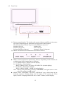
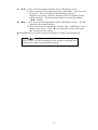
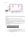
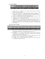
Table of Contents
1.
Safety Guidelines: ------------------------------------------------------------------------------------- 1
2.
Before Use:-------------------------------------------------------------------------------------------- 2
2.1
Open the Package
2.2
Installation
3.
Safety -------------------------------------------------------------------------------------------------- 3
4.
Product Features -------------------------------------------------------------------------------------- 9
5.
Standard Components-------------------------------------------------------------------------------- 10
6.
Names and Functions of Parts: --------------------------------------------------------------------- 11
7.
8.
9.
6.1
Side View
6.2
Front View
6.3
Rear View
6.4
Remote Controller
Connection to External Equipment----------------------------------------------------------------- 20
7.1
PC Module
7.2
PC Module + Video Module
7.3
PC Module + Enhanced PC Module
7.4
Connection to External Laud Speakers
Basic Operation--------------------------------------------------------------------------------------- 24
8.1
Power ON/OFF
8.2
Selection of Input Mode
8.3
OSD Option Adjustment
8.4
Sound Adjustment
8.5
Zooming of the Screen
8.6
Other Functions
8.7
OSD Functions
Optional Accessories--------------------------------------------------------------------------------- 33
10. Specifications ----------------------------------------------------------------------------------------- 34
11. Factory Settings--------------------------------------------------------------------------------------- 34
12. Cleaning and Simple Troubleshooting------------------------------------------------------------- 36
i
1.
Safety Guidelines:
Caution: Use a power cable is properly grounded. Always use the AC cords listed below for
each area:
USA …………………… UL
Canada………………….. CSA
Germany…………………VDE
Britain……………………BASEC/BS
Japan…………………….Electric Appliance Control Act
FCC Information
This equipment has been tested and found to comply with the limits for a Class B digital
device, pursuant to part 15 of the FCC Rules. These limits are designed to provide reasonable
protection against harmful interference in a residential installation. This equipment generates,
uses, and can radiate radio frequency energy, and if not installed and used in accordance with
the instructions, may cause harmful interference to radio communications. However, there is no
guarantee that interference will not occur in a particular installation. If this equipment does
cause unacceptable interference to radio or television reception, which can be determined by
turning the equipment off and on, the user is encouraged to try to correct the interference by
one or more of the following measures:
-
Reorient or relocate the receiving antenna.
-
Increase the separation between the equipment and receiver.
-
Connect the equipment into an outlet on a circuit different from that to which
the receiver is connected.
-
Consult the dealer or an experienced radio/TV technician for help
FCC Warning
To assure continued FCC compliance, the user must use the provided grounded
power supply cord and the provided shielded video interface cables to connect to
this equipment. Also, any unauthorized changes or modifications to this equipment
would void the user’s authority to operate this device.
1
2.
Before Use:
The product is a 46” WVGA (wide-screen with VGA resolution) Plasma Display with the
features of super thinness, high quality, flat display and non-radiation. It has passed the
Class-B EMC test and the UL and CSA safety certifications, and is an ideal product for
individual users and commercial exhibitioners.
The product is a precise electronic product. Users shall read the following instructions
carefully to bring the performance of the product into full play:
2.1
Open the Package:
The product is packaged in a carton together containing a host and other standard
accessories. The optional accessories are packed separately in another carton.
The weight of the host is about 37 kg. Since the size of the host is big, it is
recommend moving it by two persons.
The protective glass and the glass substrate are installed on the front of the product.
Since both glasses are broken and scraped easily, move then gently. Don’t put the
glasses with their faces downward without protecting them with pads.
When opening the carton, check whether the product is in good condition and all the
parts and components are packed without shortage.
Whenever possible, use the handles on the back of the Display for transport.
2.2
Installation:
Read the User Manual carefully before conducting the installation.
The power of the product is about 340~350W, somewhat higher than ordinary TV
sets. Use the jack exclusively designed for the product. When an extended line is
required, consult with your service agent to select an extended line with higher power
to avoid any risk.
The product shall be installed on a flat ground to avoid declining. The distance
between the back of the product and the wall shall be maintained for proper
ventilation.
Don’t install the product in kitchen, bathroom and other places with higher smoke,
humidity or dust to so as not to shorten the service life of the electronic components.
Please ensure the product be installed horizontally, any 90° clockwise or
counterclockwise installation may induce poor ventilation and components damage
should be avoided.
To protect the screen and elongate the usage life, do not hold on a static picture for a
long time.
In order to get the best warranty, the product must be installed by specific technician
from distributor or authorized agent.
2
3.
Safety:
Safety of operators is taken into consideration at the phrase of design and manufacturing, but
inappropriate operation may cause electric shock or fire. To prevent the product from being
damaged, the following rules shall be observed for the installation, use and maintenance of the
product. Read the following safety instructions before starting the operation.
The User Manual uses the following symbols to ensure a safe operation and prevent any
damage to operators or properties:
WARNING--- Ignorance or inappropriate use may cause damage
or vital errors to operators.
ATTENTION--- Ignorance or inappropriate use may cause injury
or material damage.
Examples:
Prohibition
Warning (Attention) symbol (indicating “Electric Shock”).
WARNING
Don’t install the product on an unstable ground:
Don’t install the product on an swinging or declining ground;
Otherwise it may drop and cause damage.
Only the marked power source can be used for the product:
The power source other than the marked one may cause fire or
electric shock.
3
Keep the product away from moisture:
* Don’t install the product close to water.
* When the product is used close to windows or
outdoors, keep it away from water.
* When water penetrates into the product, stop the
operation; unplug the connector and contact with your
dealer. Continuous use in this case may cause fire or
electric shock.
WARNING
Don’t put water containers or small metal
objects on the top of the product:
* Don’t put any water-injected cups, small potted plants,
cosmetics, medicine liquid, small containers, or metal
objects on the top of the product. The spoiled water
may cause short circuit, fire or electric shock when it
penetrates into the housing of the product.
Don’t damage the power cable:
Don’t damage or change the power cable. Heavy
objects, heat or tensile force may damage the power cable
and cause fire or electric shock.
Don’t change or open the back cover:
Changing the product may cause fire or electric shock.
Don’t remove the back cover of the product to avoid
possible electric shock.
Contact the manufacturer when inspection or adjustment is required.
Don’t use the product when any abnormality occurs:
Continuous use of the product in the case of smoking or
odor spreading may cause fire or electric shock. Unplug
the connector and contact the manufacturer immediately.
Don’t try to repair the product by yourself to avoid any
risk.
4
WARNING
Don’t drop or damage the housing:
In the case the product is dropped and the housing is
damaged, the internal components may function
abnormally. Unplug the connector immediately and
contact the manufacturer for repair. Continuous use of
the product may cause fire or electric shock.
WARNING
Don’t touch the power jack during lightening:
Don’t touch the power jack during lightening to avoid
electric shock.
ATTENTION
Don’t install the product close to smoke or moisture:
Fire or electric shock may be caused when the product is
installed close to smoke or moisture.
Don’t installed the product in a place with
heavy dust or high humidity:
Fire or electric shock may be caused when the product is
installed in a place with heavy dust or high humidity.
Instructions about moving the product:
Make sure that the power connector and other plugs are
all unplugged before moving the product. The product
shall be moved by at least two persons.
5
The power cable shall be kept away from heat
sources:
The heat produced by any heat source may fuse the
covering of the power cable.
Hold the power connector when remove the
power cable:
Pulling the power cable may damage the wires inside the
cable and cause fire or electric shock.
Unplug the connector
Don’t touch the connector with wet hands:
Electric shock may be caused in this case.
ATTENTION
Insert
batteries
instructions:
in
accordance
with
Insert the batteries with correct polarities (positive + and
negative -). Incorrect polarities may case breakage and
leakage of the batteries, hurt operators and contaminate
the remote controller.
Don’t charge the batteries
attached with the product to avoid any risk.
Don’t put any object on the vents:
Blocking the vents may raise the internal temperature and
make the housing hot or cause fire.
Touching the hot housing may hurt operators. Don’t
install the product in a place with narrow space or bad
ventilation. Don’t cover the vents with towels, blankets
or dusters.
When the product is unused for a long time:
Unplug the power connector and other plugs when the
product will not be used for a long time.
Unplug the connector
6
3.1 Read all safety instructions and the User Manual before using the product.
3.2 The safety instructions and User Manual shall be maintained in good condition for future
use.
3.3 Special attention shall be paid to the warnings on the User Manual.
3.4 The User Manual shall be observed when using the product.
3.5 Unplug the power connector before cleaning the product. A wet cloth is sufficient for
the cleaning of the product and don’t use liquid or spraying cleaner for cleaning purpose.
3.6 Use the accessories recommended by the manufacturer to avoid any risk.
3.7 Keep the product away from any water source. When moving the product from lower
temperature to high temperature environments, drops of water may condense on the
housing. Don’t turn on the Display immediately so as not to cause fire, electric shock or
other risks.
3.8 Don’t install the product on unstable wagons, racks or tables to avoid falling, hurt or
material damage. The installation of the product shall be conducted in accordance with
the instructions of the manufacturer and by using the support recommended by the
manufacturer.
3.9 When installing the product on a wagon, emergency stop or forceful push of the wagon is
prohibited. It is also not allowed to drive the wagon through an uneven ground to avoid
falling, hurt or material damage.
3.10 The openings on the back of the product provide a ventilation function and can ensure the
reliability of the operation from being affected by overheats. The vents shall not be
blocked or closed, especially when the product is installed on your bed, sofa, blanket or
other similar surfaces. Expect for a good ventilation condition is available, don’t
installed the product in an embedded rack or bookcase. The installation shall be
conducted in accordance with the instructions of the manufacturer.
To ensure good ventilation, a distance of more than 10cm shall be maintained
between the Display and any other furniture.
3.11 Energize the product with the voltage specified on the power supply label. Contact your
dealer or local power station when you don’t know the voltage of your power source.
3.12 The three-wire power connector attached to the product shall only plug into the jack with
a grounding terminal. When you encounter any difficult in the plugging of the power
connector, contact electricity technicians for assistance and don’t damage the ground
terminal of the power connector.
3.13 The power cable shall be fixed along with its patch. Don’t lead the power cable through
the passageway or have it pressed by other objects. Special attention shall be paid to the
wiring at the door and of the power connector and other plugs and jacks.
3.14 when it lightens or the product will not be used for a long time, remove the power cable
and all other cables from the jacks to avoid any damage caused by the lightning or the
surge of the power source.
3.15 Don’t overload the power jack. Using extended lines or the jacks of other appliances
may cause fire of electric shock.
3.16 Don’t put any object from the vents; otherwise, high voltage may be induced and causes
short circuit, fire or electric shock. Water sprayed to the product is prohibited.
3.17 Opening or removing the back cover may expose you in high voltage or other risks.
When repair is required, contact qualified service staffs and don’t repair the Display by
yourself.
3.18 Unplug the power connector and contact with qualified service staffs when the following
incidents occur:
The power supply or connector fails.
Liquid sprays or any object drops into the Display.
7
The Display exposes in the rain.
When the Display cannot operate in normal condition, adjust it in accordance with
the User Manual. It may take more time to remove the damage caused by
inappropriate adjustment.
The Display drops or damages under any circumstances.
The performance of the Display changes substantially.
3.19 When it is required to replace parts, make sure that the service staffs use the parts
specified by the manufacturer or with the features same as the replaced parts. Unqualified
substitutes may cause fire, electric shock or other risks.
3.20 When the repair is completed, the service staffs shall conduct a safety inspection to
ensure normal operation of the product.
3.21 A distance of at least 1 meter shall be maintained between the product and any heat
source, such as radiator, heater, electrical oven, amplifier and other heat producing
devices.
3.22 Turn off the power of the product to avoid electric shock before connecting it to other
devices, such as VCR or PC.
3.23 Only use the special cable approved by manufacturer to avoid any electric shock.
3.24 The rated voltage is AC 100V~120V/220V~240V.The power source used shall have such
voltage. It is recommended to use the power cable specified by you dealer for the sake
of safety and EMC.
3.25 The power cable must be replaced when using different voltage from that specified in the
User Manual. For more information, contact your dealer.
3.26 Operating environment:
Temperature 32oF~104oF (0oC ~ 40oC)
Humidity 20% to 85% non-condensing
Atmospheric pressure 800 to 1100hPa
8
4.
Product Features:
The machine uses a Plasma Display Panel with a thickness of 9.8cm. It provides quality image
displays and is an ideal choice for multimedia applications.
4.1 Available for multiple input signals:
The standard PC module provides RGB (D-SUB15 PIN) and digital DVI input
connectors, and a RS-232 communication connector (D-SUB 9 PIN MALE).
The Video module provides composite video(RCA),S-video (DIN 4P) and
component video (RCA) input connectors, and a composite video (BNC) output
connector. It supports the quality images input of DVD and HDTV
(480P/720P/1080i), as well as the images of TV systems such as NTSC, PAL and
SECAM. The Video module also provides two sets of stereo input connectors
(RCA).
The enhanced PC module provides two sets of RGB input connectors (one set each
for D-SUB15 PIN and RGBHV 5 line BNC) and one set of RGB output connectors
(D-SUB15 PIN). A set of PC sound input connectors is also provided.
The machine supports PC image quality up to XGA (1024X768) with a vertical
frequency of 85Hz.
4.2 Power Management Function: The machine provides an automatic power saving
function.
4.3 Fan-free Design: The power of the machine is effectively lowered and does not require a
fan for ventilation, eliminating any bothersome noise that may be generated by fans.
4.4 Others:
PIP Function: The user may watch video while working with his or her PC.
The machine has a set of built-in 2.0W loudspeakers, and can connect to external
10W+10W loudspeakers.
The Machine provides high, medium and low color temperature options. The user
may customize their favorite color temperature.
The user may work with the video module or enhanced PC module to expand the
applications of the machine to meet any special demands.
9
5.
Standard Accessories:
User Manual x 1
Power Cord x 1
Note: Depending on the shipping areas, the
actual attached to the product might
be different.
S- Video cable x 1
D-sub 15 PIN Cable x 1
AV- Cable x 1
Component- Cable x 1
Battery UM-4 x 2
Remote controller x 1
10
6.
Names and Functions of Parts:
6.1 Side View:
Power switch
Power cable
Power jack
Power jack on the wall
Plug the power cable attached to the product into the power jack on the right side of
the product. Plug the other end of the power cable into the power jack on the wall.
Press the power switch (0: Off, 1: On). The power indicator in the front of the
Display lights red, indicating that the display is in a standby state.
11
6.2
Front View:
(1) Remote control window: The window with a power indicator and IR receiving sensor
are used for indicating power status and receiving remote control signals.
The indicator shows whether the power of the Display is turned on.
Indicator ON (red)
Standby state.
Indicator ON (green)
Power ON state.
Indicator flashing (red/green)
alternately: Power Saving state
(2) Button: The functions of the buttons are described as follows:
INPUT:Select appropriate signal source directly. (Depending on the module, the
available signal source options may be different)
A. PC Module: RGB 1→RGB 2 (circular display).
B. PC Module + Video Module:
RGB 1→RGB 2→AV1→S-Video→Y Cb/Pb Cr/Pr (circular display).
C. PC Module + Enhanced PC Module:
RGB 1→RGB 2→RGB 3→RGB 4 (circular display).
Note: When pressing this button to display “OSD Menu”, the signal sources can be
selected by using the ▲/▼ buttons.
MENU: Enter “OSD Menu” and select “OSD Menu” page, which shows in the
following sequence: Display→Image (for PC input) or AV system (for Video
input)→Audio→Language and Screen Saver→Misc.→Status (circular display).
12
▲/▼: A. They are used as up/down buttons in the “OSD Menu” screen.
B. They are used for quick adjustment when “OSD Menu” is not shown on
the screen. The screen shows in the following sequence:
Brightness→Contrast→Volume→Height→Bass→Left/Right Volume
(circular display). The adjustment is made in conjunction with the
“.◄/►.” buttons.
◄/►: A. They are used as left/right buttons in the “OSD Menu” screen. The “►”
button has the function of Enter.
B. They are used for the adjustment of volume with “OSD Menu” is not
shown on the screen. Press “◄” can reduce the volume, while press
“►” can increase the volume..
STANDBY/ON: It is used to activate the Display or bring it into standby state.
WOW
Is the trademark of SRS Labs, Inc.
The license to use WOW technology for the product is acquired from
SRS Labs, Inc. when compiling this document.
13
6.3
Rear View:
(1) Speaker Connection Terminals: Each one set of speaker connection terminals on the
left and right sides is used to connect to the speaker with more than 10W(L/R) and
8~15Ω.
(2) Stand.
(3) Four tapped holes for the Stand: Use the standard screws to fix the seat.
(4) Four tapped holes for the wall mount (optional): Use the standard screws to fix the
wall mount.
(5) Transport handles: Use the handles to facilitate the transport. When wall mount is
used, the handles shall be removed before assembling the Display with wall mount.
(6) Four tapped holes for the laud speakers: Use the standard hangers and screws to fix
the optional standard laud speakers.
(7) Signal input terminals: They are used to connect to input devices. Depending on
the selected modules, there are three combinations available for selection:
PC Module
A. D-Sub: Connects to the D-SUB 15 PIN analog output connector of the PC
display card. The Display is used as a PC monitor.
B. DVI: Connects to the DVI-I digital output connector of the PC display card.
The display is used as a PC monitor.
C. RS-232C: is a D-SUB 9 PIN male terminal used as a control port for serial
communication.
14
Video Module
A. CVBS Out: is a composite video output terminal (BNC connector)
connecting to other displays.
B. Audio 2: Is an audio input terminal connecting to the audio output terminal
of the video output device. CVBS In and S-Video share this terminal.
C. CVBS In: is a composite video input terminal (RCA connector) connecting
to the video output terminal of the video output devices.
D. S-Video: is a Y/C S-Video input terminal (DIN 4 PIN) connecting to the
S-output terminal of the video output device.
E. Y/CbPb/CrPr: is a component video input terminal (RCA connector)
connecting to the component output terminal of the video output device.
F. Audio 1: is an audio input terminal connecting to the audio output terminal
of the video output device. The component video and PC input signals share
this terminal.
Enhanced PC Module
A. D-Sub Out: is a D-SUB 15 PIN analog video output connector connecting to
other displays and used as a second output device. (Refer to 7.3.)
B. R/G/B/Hs/Vs: is a five-wire analog input connector (BNC connector)
connecting to the horizontally and vertically synchronous red/green/blue
output terminals of the PC display card.
C. D-Sub In: Connects to the D-SUB 15 PIN analog output connector of the
PC display card. The Display is used as a PC monitor.
D. PC Audio: Connects to the audio output connector of the PC sound card.
The Display can output PC sound.
15
6.4
Remote controller:
1
3
4
2
5
6
7
8
9
11
10
12
15
13
14
6.4.1 Functions of keys:
1. Power: Press this key in the standby state to turn on the Display. Press this
key when turning on the Display to return to the standby state.
2. Video: Press this key to switch the video signal sources. The signal sources
switch in the following sequence: AV1, S-Video, Y Cb/Pb Cr/Pr.
3.
(AUTO): A. The Display adjusts the phase, vertical/horizontal position
and color temperature automatically when pressing this key
in PC mode.
B. The Display chooses appropriate video format automatically
when pressing this key in Video mode.
4. PC: Press this key to switch PC signal sources. The signal sources switch in
the following sequence: RGB 1 (PC Module D-Sub Terminal), RGB 2 (PC
Module DVI Terminal), RGB 3 (Enhanced PC Module D-Sub Terminal),
RGB 4 (Enhanced PC Module RGB BNC Terminal).
16
5. Menu◄/Menu►: Switch OSD pages in the following sequence (circular
display):
Display—Image or AV System— Audio-- Language and Screen Saver--- Misc.--- Status
6.
Input: Press this key to select the signal sources directly. (Depending on the
module, the available signal source options may be different.)
A. PC Module: RGB 1→RGB 2 (circular display).
B. PC Module + Video Module:
RGB 1→RGB 2→AV1→S-Video→Y Cb/Pb Cr/Pr (circular display).
C. PC Module + Enhanced PC Module: RGB 1→RGB 2→RGB 3→RGB 4
(circular display).
Note: When pressing this button to display “OSD Menu”, the signal sources
can be selected by using the ▲/▼ buttons.
7. Wide: Press this key to switch to wide screen. Pressing this key again can
restore the original size of the screen.
8. ▲ ▼: Use these keys to adjust “OSD Menu” up and down.
9. ◄ ►: Use these keys to adjust “OSD Menu” left and right.
10. Exit: Press this key to exit “OSD Menu”.
11. Zoom+/ Zoom-: Use these keys to zooming the screen.
12. Vol+/ Vol-: Use these keys to adjust the volume.
13. PIP: Use this key to adjust the size of the sub-picture in the following
sequence:
Sub-picture open (small)→Screen (middle)→Screen (large)→Sub-picture
closed (circular display).
14. Freeze: Press this key to suspend the current screen. The playback system
keeps playing when the screen is frozen. You may press this key again to
continue playing or resume play automatically after one minute.
15. Mute: Press this key to mute the laud speakers. Press it again to restore the
audio output.
17
6.4.2 Insertion of Batteries:
Press here
1.
2.
3.
As shown in the above figure, press the position pointed out by the arrow and
push the cover out of its location.
Insert two No. 4 batteries in the remote controller as shown in the above
figure.
Re-assemble the cover in a reversed procedure and confirm the fastener of the
cover has fixed in the right position.
6.4.3 Scope of Remote Control:
6M(Front)
18
Make the remote controller point to the remote control window (i.e. the
window showing the power indication) of the Display to receive the signals
transmitted from the remote controller.
No obstacles shall be placed between the remote controller and the remote
control window.
The effective receiving scope of the signals is 6 meters to the front of the
remote control window, each 30° to the left and right sides and each 20° to
the top and bottom of the control window.
6.4.4 Use of Remote Controller:
1. To ensure a normal operation, the remote controller shall not be stricken or
fall on the ground. It shall also be kept dry and away from heat sources.
2. Don’t wipe the remote controller with wet cloth moistened with volatile
solvent, such as benzene or thinner.
3. When the response of the Display becomes abnormal, check whether the
energy of the batteries is too weak.
19
7.
Connection to External Equipment:
7.1
PC Module:
PC module is used as a PC monitor for the PC display card.
D-SUB (15 PIN) connects to analog RGB output interface (Input option RGB 1).
DVI connects to digital RGB output interface (Input option RGB 2).
Note: 1. The DVI connector of the Display is DVI-I, which does not support analog
signal input.
2. The RS-232 connector of the Display provides a transmission interface for
professional technicians to update firmware, without providing additional
communication functions.
20
7.2
PC Module + Video Module:
The functions of D-SUB, DVI and RS-232 terminals are same as the PC module.
The component terminal (Y/PbCb/PrCr) connects to the component output of a
video output device (such as DVD or HDTV TUNER). The sound is input via
Audio 1 (INPUT Option Y Cb/Pb Cr/Pr).
S-Video terminal connects to the Y/C S-Video output of a video output device
(such as S-VHS or DVD). The sound is input via Audio 2 (INPUT Option
S-Video).
CVBS In terminal connects to the CVBS (Video) output of a video output device
(such as VHS, VCD, S-VHS or DVD). The sound is input via Audio 2 (INPUT
Option AV1).
The S-Video and CVBS In of the Display share the Audio 2 input.
The CVBS Out terminal connects to another TV or display and transmits the
signals input via CVBS In to the other display. The Display uses BNC terminal
to ensure the quality of the output signal.
The display to be connected might need an adapter for the transmission.
21
7.3
PC Module + Enhanced PC Module
RGB 4 (BNC)
RGB 3 (D-SUB)
RGB 1 (D-SUB)
RGB 2 (DVI)
The functions of D-SUB, DVI and RS-232 terminals are same as the PC module.
The Display provides 4 sets of RGB inputs (3 analog and 1 digital) and 1 set of
RGB output.
3 sets of analog inputs, including 2 sets of D-SUB terminals (INPUT Option RGB
1 and RGB 3) and 1 set of 5-axial BNC terminals (INPUT Option RGB 4).
PC-Audio can be used in conjunction with any one set of RGB inputs.
D-SUB OUT provides only adapter output for RGB 3 and RGB 4 input signals.
22
7.4
Connection to External Laud Speakers:
PDP Rear View
Speaker (Optional)
Speaker Wire
Speaker Terminal
Speaker Wire
Press the terminal of one speaker down to its end position, extend the wire of the
speaker (remove the insulator at the front side) into the bottom of the terminal,
and restore the terminal to its original position.
Pull the wire gently to make sure that the wire is fastened firmly.
Note 1: The wiring of the left and right speakers is the same.
Note 2: When connecting to external speakers, set the speaker to External mode in the
“Audio” page of the “OSD Menu”. (Refer to 8.7.2.)
Note 3:Please use the special speaker line enclosed this speaker , otherwise we can not
assure you that our product can fit the standard of electro magnetic
interference.
23
8.
Basic Operation:
8.1 Power ON/OFF: The operation is in Standby mode:
Press the “POWER’ key to turn on the Display. The power
indicator changes from red to green.
Press the “POWER” key in the Start state to turn off the Display.
The power indicator changes from green to red.
(Note: The power indication flashes for a few seconds before switching
the color.)
8.2
Selection of Input Mode:
Press the “INPUT” key. The “OSD Menu” of input signal sources
appears. Use the “▲/▼” keys to select the signal source you want
and press “►” to confirm the selection.
Your may also press the “INPUT” key repeatedly to select the signal
source you want. The signal sources are displayed in the following
sequence (depending on the module, the sequence might be
different):
Where:
1. PC Module:
RGB1→RGB2
1. PC Module + Video Module:
RBG1→RGB2→AV1→S-Video→Y Cb/Pb Cr/Pr
2. PC Module + Enhanced PC Module:
RGB1→RGB2→RGB3→RGB4
RGB 1: Analog D-SUB input on PC module.
RGB 2: Digital DVI-D input on PC module.
RGB 3: Analog D-SUB input on enhanced PC module.
RGB 4: 5-axial BNC input on enhanced PC module.
24
8.2.1 Selection of VIDEO Input Mode:
Press the “Video” key repeatedly to select the signal source for
Video module. The signal sources are displayed in the following
sequence:
AV1→S-Video→Y Cb/Pb Cr/Pr
8.2.2 Selection of PC Input Mode:
Press the “PC” key repeatedly to select the signal source for PC and
enhanced PC modules. The signal sources are displayed in the
following sequence:
Where:
1. PC Module:
RGB1→RGB2
2.PC Module + Enhanced PC Module:
RGB1→RGB2→RGB3→RGB4
RGB 1:
RGB 2:
RGB 3:
RGB 4:
Analog D-SUB input on PC module.
Digital DVI-D input on PC module.
Analog D-SUB input on enhanced PC module.
5-axial BNC input on enhanced PC module.
25
8.3
OSD Option Adjustment:
The keys for OSD option adjustment include: “Menu◄”, “Menu►”,
“▲”, “▼”, “◄”, “►” and “Exit”.
Press the “Menu◄”, “Menu►” to open “OSD Menu” or select the
page at the left or right side. The pages are displayed in the
following sequence (circular display):
Display
Image or AV system
Audio
Language and
Screen Saver
Misc
Status
Use the “▲/▼” keys to select OSD pages up and down.
Use the “◄/►” keys to select OSD pages left and right. You can
also use these keys to increase and decrease the value. The right
“►” key has the function of Enter.
Press the “Exit” key to exit the current OSD page.
Note: The OSD Close Time is set from the Misc. page. When no
key is pressed within the set time, the system exits the OSD
Option Page automatically.
8.4
Sound Adjustment:
The keys for audio adjustment include: “Vol +”, “Vol -” and “Mute”.
Press and hold the “Vol +” to increase the volume and press and hold
the “Vol -” to decrease the volume.
The Display is in the mute state when you press the “Mute” key, and
restore to the original state when you press the same key again.
Other audio adjustment (such as treble, bass and balance) must be
executed from “OSD Menu”.
26
8.5
Zooming of the Screen:
The Zooming keys include “Wide”, “Zoom +” and “Zoom –”.
By pressing the “Wide” key, you can zoom in the screen to its
largest size. You can then restore the screen to the original size by
pressing the “Wide” key again.
Note: 1. When PC signals are input, you can switch between the full
screen size and the original signal strength.
2. When video signals are input, you can switch among six
screen sizes, including Full, Fill Aspect Ratio, 4:3 to 16:9,
LB to 16:9, LB Subtitles to 16:9 and Anamorphic.
By pressing and holding the “Zoom +” key, you can zoom in the
screen gradually. By pressing and holding the “Zoom –” key, you
can zoom out the screen gradually to its original size.
Note: 1. You can only zoom out the screen gradually to its original
size by pressing the “Zoom –” key. The screen cannot be
zoomed out to a smaller size with this function.
2. When the image is zoomed in by using the “Zoom +” key,
you can use “▲”, “▼”, “◄” and “►” keys to adjust the
viewing area.
8.6
Other Functions:
When the display cannot be showed after the change of the timing in
PC Input mode, press the
(AUTO) key. The machine will
automatically adjust the phase, horizontal/vertical position and color
temperature to optimize the display.
When the display cannot be showed after the change of the playback
system in Video Input mode, press the AUTO key. The machine will
select the appropriate format for the image system.
Note: For the information about the timing provided by the machine,
refer to Chapter 11.
Press the “Freeze” key to freeze (or suspend) the current screen.
You may press the “Freeze” key again to continue the playing.
Note: You can only freeze the screen by pressing the “Freeze” key. The
playback system keeps playing when the screen is frozen.
You can press the “PIP” key to show the picture-in-picture screen.
The screen will change as follows when you press the “PIP” key
consecutively:
Sub-picture open (small) → Screen (middle) → Screen (large) → Sub-picture closed
Note: The picture-in-picture screen can receive video images while the
PC outputs the display to the Main Screen, so the prerequisites for
the display of the sub-picture include:
1. A video module.
2. The Main Screen must be a PC display.
3. The video image source must be connected appropriately.
The position to display the sub-picture and the video image source
must be set from the OSD menu.
27
8.7
OSD Functions:
8.7.1 General Description of OSD Function Pages:
PC:
Display
Brightness
Contrast
Red
Green
Blue
Reset
Image
H. Position
V. Position
Phase adj.
Sync adj.
Aspect Ratio
DPMS
Audio
Volume
Treble
Bass
Balance
Mute
Speaker
Language and
screen saver
Language
Image Reverse
Image Move
Move Time
WOW
Advanced Mode
Gamma
Color Space
PC User
Misc.
OSD Position
OSD Timeout
OSD Rotation
Color Temp.
Reset to default
PIP Settings
Status
Resolution
V Frequency
H Frequency
PIP Input
PIP System
PIP Setting:
Display
Misc.
Brightness
PIP Size
Contrast
PIP Source
Saturation
PIP Position
Hue
Sharpness
Reset
AV:
Display
AV System
Brightness
Contrast
Saturation
Hue
Sharpness
Aspect Ratio Volume
Video Format Treble
Bass
Balance
Mute
Reset
Audio
Speaker
Language and
screen saver
Language
Image Reverse
Image Move
Move Time
WOW
Misc.
Status
OSD Position Input Source
OSD Timeout System
OSD Rotation
Color Temp.
Reset to
Default
Advanced Mode User Color
Temp.
Gamma
Color Space
User Color Temp:
Display
(1)
Red
Green
(2)
Blue
(3)
(4)
There are each 6 pages for the PC module and Video module, but the
adjustable items might be different.
The PC module provides PIP function and has two additional adjustable
pages for PIP images.
An adjustable User Color Temp page is added for the video module.
A selection page is provided for Advanced Mode of the Language and Screen
Saver page.
Note: The User Color Temp. page of the PC module is adjustable. No other
adjustable pages are added for the PC module.
28
8.7.2 Functions of OSD Pages:
(1) Display Page:
PC
VIDEO
50
50
50
50
50
50
50
50
50
50
The brightness, contrast and reset can be adjusted when inputting PC signals. The
brightness of the red, green and blue can be adjusted when selecting “User Color Temp”
from the Misc. page.
The brightness, contrast, saturation, hue, sharpness and reset can be adjusted when
inputting Video signals.
(2) Image and AV System Page:
PC
VIDEO
50
50
AUTO
16
50
When inputting PC signals, the horizontal position, vertical position, phase and
synchronous signals can be adjusted, and the aspect ratio and DPMS is enabled or disabled.
You can adjust the screen and select the signal format you want when Video signals are
input. When you don’t know which signal format is to be selected, select “Auto
Selection”. The Display will select the signal format for you automatically.
The Display provides six aspect ratio formats. You can select the most suitable format
for the selected signal source. Press the “◄/►” keys on the remote controller or the
Display to select Full, Fill Aspect Ratio, 4:3 to 16:9, LB to 16:9, LB Subtitles to 16:9 and
Anamorphic sequentially.
29
(3) Audio Page:
39
50
50
0
The adjustable items of this page, including volume, treble, bass, balance and mute, are the
same when inputting PC or Video signals. Internal and external speakers can be selected
on this page.
(4) Language and Screen Saver Page:
PC
Options in Advanced Mode
1
VIDEO
Options in Advanced Mode
1
You can select the languages provided by OSD from the “Language” option. The preset
languages of the Display include English, Traditional Chinese, Spanish, and Portuguese.
To protect the screen of the product, set the “Image Reverse”, “Image Move” or “Move
Time” function to protect the screen when a static screen is displayed for a long time.
30
Note: The plasma display is coated with phosphor (same as CRT). When the screen
is displaying statically for a long time, an image sticking may appear and affect
the quality of the image. The screen saver forces to move the image at a given
time to avoid producing image sticking.
(5) Misc. Page:
PC
VIDEO
10
10
The function of this page includes OSD Position (9 positions), OSD Timeout, OSD
Rotation (by 90°), Color Temp, Reset to Default and PIP Setting.
The “PIP Setting” option is enabled when inputting PC signals (the
Video/S-Video/Component terminals must have input signals for this option). Press the
button on the Display or the “►” key on the remote controller to complete the settings as
shown on Fig. 5-1.
Select “User” from “Color Temp” when inputting Video signals, and press the button on
the Display or the “►” key on the remote controller in the “User Color Temp” option to
complete the settings as shown in Fig. 5-2.
Note: To select “User” from “Color Temp”, your must set the brightness of
red/green/blue on the “Display” page.
(5-1) PIP Setting (for PC mode only):
50
50
50
50
50
To access the options of the page, select “PIP Setting” from the “Misc.” page when
inputting PC signals.
The “Display” page is same as the “Display” page in Video mode. The “Image” page is
used to enable and disable PIP, set PIP size, PIP source and PIP position.
31
(5-2) User Color Temp (for AV mode only):
50
50
50
Access to the input screen of the “User Color Temp” option when inputting Video
signals.
(6) Status:
PC
VIDEO
640
480
Video 1
60
31.46
PAL
50Hz / 4.43MHz
Video 1
PAL 50Hz / 4.43MHz
This page displays resolution and vertical/horizontal frequency when inputting PC signals.
When PIP is used, the sub-picture source and systems are also displayed.
The signal source and system is displayed when inputting Video signals.
32
9.
Optional Accessories:
Install the PDP SET to the Stand
Stand
Speaker
Wall Mount
Inclination 0 - 25° adjustable
Ceiling Mount
33
11. Factory Settings:
The manufacturer has setup 17 signal modes as shown in the following table:
Factory Signal Settings (for RGB mode)
Dot Clock
Vertical
Horizontal
Resolution
Frequency
Frequency
Frequency
NO
Horizontal
(MHz)
(Hz)
(KHz)
1
720×400
31.47
70.08
25.17
2
640×400
37.90
85.00
31.50
31.50
60.00
3
640×480
25.18
4
640×480
35.00
67.00
30.24
5
640×480
37.50
75.00
31.50
6
640×480
37.86
72.81
31.50
7
640×480
43.30
85.00
36.00
8
800×600
35.16
56.25
36.00
9
800×600
37.90
60.32
40.00
10
800×600
46.90
75.00
49.50
11
800×600
48.08
72.19
50.00
53.70
85.00
12
800×600
56.25
13
832×624
49.00
74.00
57.27
14
1024×768
48.40
60.00
65.00
15
1024×768
56.50
70.00
75.00
16
1024×768
60.00
75.00
78.75
17
1024×768
68.70
85.00
94.50
Remark
DOS
VESA
DOS
Mac.(SOG)
VESA
VESA
VESA
VESA
VESA
VESA
VESA
VESA
Mac.(H+V)
VESA
VESA
VESA
VESA
* When the signal received by the Display exceeds the allowed range, an warning message
“Out Of Range” appears on the screen.
* You can confirm the input signal format by selecting the “Status” option from “OSD
Menu”.
35
12. Cleaning and Simple Troubleshooting:
12.1 Important:
(1) Make sure that the power cable is removed from the jack before cleaning the
Display.
(2) Don’t use volatile solvent (such as toluene, rosin and alcohol) to clean the Display,
because such chemical material may damage the housing, screen glass and remote
controller, and cause the peeling of the paint.
12.2 Cleaning of Housing and Remote Controller:
(1) Use a soft cotton cloth for cleaning.
(2) When the housing or remote controller is seriously contaminated, use a soft cloth
moistened with diluted neutral cleaner and clean the Display. Wring water out of
the cloth before cleaning to prevent water from penetrating into the housing. Wipe
the Display with a dry cloth after the cleaning.
12.3 Cleaning of Screen:
(1) Use a soft cotton cloth to clean the screen gently.
(2) The screen glass is very fragile; so don’t scrape it with any sharp object. Don’t
press or tap the screen to avoid cracking. When the screen is seriously
contaminated, use a soft cloth moistened with diluted neutral cleaner and clean the
Display. Wring water out of the cloth before cleaning to prevent water from
penetrating into the housing. Wipe the Display with a dry cloth after the cleaning.
12.4 Simple Troubleshooting: Check the Display in accordance with the following instructions
when it fails. Also check the peripherals to find out the cause of the failure. When the
Display doesn’t work after you take the measures below, contact with your dealer for
assistance.
Failure
Measures
Power cannot be turned on.
。 Check that both ends of the power cable are plugged into the
(Power indication does not
jacks appropriately.
light)
”No Input Signal” message
。 Check that the signal line is connected appropriately.
appears.
。 Check that the power of relevant peripherals are turned on.
。 Check that the OSD option selected matches with the input
signal.
The remote controller doesn’t
。 Check that the polarity of the battery is correct.
function normally.
。 Check that the batteries do not exhaust. (Use new batteries.)
。 Check that the remote controller is used within its operating
range.
。 Check that the remote controller is pointed to the Remote
Control window of the Display.
。 Check that there is no obstacle between the remote controller
and the Remote Control window.
* For more information about the remote controller, refer to
Chapter 8.
Flashing spots or stripes appear 。 Check that there is no emitter sources (such as car, train, high
on the screen.
voltage cable and neon lamp) or other possible interference
sources that may affect your hi-fi equipment.
Image color or quality
。 Check that all the video settings are completed appropriately,
deteriorates.
such as brightness, contrast, color and other setting.
* For more information about video settings, refer to “OSD
Functions” of Chapter 8.7.
36
Screen position and size are
incorrect.
Image or color is incorrect.
The external speaker does not
sound.
The power indicator flashes
The input image and signal is
not received appropriately.
“Out of Range” message
appears on the screen.
。 Check that the screen position and size is adjusted
appropriately.
。 Check that the signal line is connected appropriately.
。 When connecting to PC, you can change the resolution of PC
to acquire correct image. The discrepancy of the PC output
signal may affect the display of the image.
。 Check that the line is connected appropriately.
。 Check that the Display is not in “Mute” mode.
。 Check that the audio signal lines of the peripherals are
connected appropriately.
。 Check that the signal line is fixed appropriately.
。 Check that the screen is in a power save state.
。 Input correct signal
* For more information, refer to “Factory Settings” of Chapter
11.
37