1
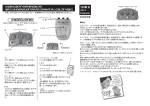
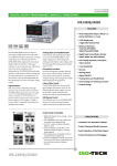
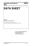
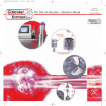
User Manual
SYSTEM 1 000 I 2000 I 4000 I 8 000
2
System 1000 I 2000 I 4000 I 8000 user manual
Manual
SYSTEM 1000 I 2000 I 4000 I 8000
Please read this manual carefully before attempting to install a Smokecloak
system. Please hand the “End-User Guide” to your customer.
3
Conventions
The following symbols are used in this manual to help
you install the Smokecloak system correctly and safely.
Gives useful advice or suggestions to enhance the
performance of the Smokecloak system.
Indicates important information that is critical for the
correct use of your products and must always be read
carefully.
It is essential that only genuine Smokecloak fluid
is used. Damage to the equipment and possible
health hazard is likely if incorrect fluid is used. The
warranty on all of the equipment will also be void.
Under no circumstances should the on board power
supplies of the Smokecloak (terminals 1, 6, 19, and
20) be linked to any other 3rd party equipment e.g.
alarm panels, additional power supplies, etc. as this
could cause unexpected faults within the machines.
MSS Professional A/S
Brunbjergvej 6
8240 Risskov
Denmark
Telefon+45 7217 0011
Fax
+45 8617 0055
MSS Professional Ltd.
Rectory Court, High Street
Kislingbury
Northampton
Northants
NN7 4AG
England
Phone +44 (0)1604 839000
Fax
+44 (0)1604 832666
4
System 1000 I 2000 I 4000 I 8000 user manual
Contents
1.
SMOKECLOAK PARTS................................................4
Machine layout.......................................................4
2.
SPECIFICATIONS.......................................................8
3.
REQUIREMENTS......................................................10
4.
INSTALLATION......................................................... 12
Mains Wiring........................................................ 12
5.
MOUNTING.............................................................. 13
6.
FLUID...................................................................... 21
Bottle positioning................................................. 22
7.
BATTERIES.............................................................. 24
8.
CLOAKSENSOR....................................................... 28
Cloaksensor wiring................................................ 30
9.
CLOAK TIMING........................................................ 32
Cloak Timing switches........................................... 33
10. ALARM PANEL CONNECTIONS................................ 34
Connection examples............................................ 38
11.
FAULT OUTPUTS..................................................... 40
12.
VERIFICATION SENSOR...........................................44
13.
FINAL TEST............................................................. 45
14.
MAINTENANCE....................................................... 48
15. FAULT FINDING....................................................... 50
Flow chart........................................................... 50
16.
EXAMPLES OF TYPICAL INSTALLATIONS.................. 54
17.
ACCESSORIES......................................................... 58
18.
NOTES.................................................................... 64
19.
SMOKECLOAK INSTALLATION CHECK LIST................ 69
Contents
5
10
1
2
5
3
9
6
7
4
8
Smokecloak parts
6
1. Cover left side.
2. Fluid sensor.
3. Fluid FL600.
4. Pump(s).
5. Tamper protection.
6. Thermal trip.
7. Finger guard.
8. Output nozzle.
9. Front panel.
10. Mains.
Smokecloak Parts
15
11
14
12
13
17
16
11. PCB.
12. Cable grips.
13. Loom Cable 20Way IDC.
14. PCB Smokecloak interface.
15. Cover right side.
16. Battery.
17. Battery cable.
Smokecloak Parts
7
F5
F4
PL 9
PL
PL
PL
PL
13
15
23
8
F2
PL 7
PL 17
PL 18
E
PL 14
PL 12
PL 3
PL 4
F3
PL 1
PL 2
PL 22
PL 21
PL 20
PL 19
LD 1
SP 1
PL 16
PL 6
SW 2
SW 1
Main Board
PL
PL
PL
PL
PL
PL
PL
PL
PL
PL
PL
PL
PL
PL
PL
PL
PL
PL
PL
PL
PL
E
8
1
2
3
4
5
6
7
8
9
12
13
14
15
16
17
18
19
20
21
22
23
Connecters
PL 5
Expansion port.
IDE connector for interfaceboard
Connector for fluidsensor - Low fluid
Connector for fluidsensor - No fluid
Connector for battery -.
Connector for battery +.
Low voltage transformer connection.
Mains transformer connection (brown).
Mains input
Not connected.
Not connected.
Connector for heater (brown).
Connector for heater (blue).
Connector for pump(s) +.
Connector for pump(s) -.
Connector for pump(s) -.
Thermal trip (white).
Thermal trip (white).
Thermo couple.
Thermo couple.
Mains transformer connection (blue).
Chassis connection (PL 10).
SW 1
SW2
F2
F3
F4
F5
LD 1
SP 1
Smokecloak Parts
Switches
Cloaktiming (see section on cloaktiming on page 32).
Switch for future expansion.
Fuses
Transformer fuse output.
Battery fuse.
Heater fuse
Transformer fuse input.
Leds
Heating system active.
Audible
System speaker.
LD 9
PL 5
LD 10
PL 4
PL 3
PL 1
SW 1
PL 2
PL 7
LD 8 LD 7 LD 6 LD 5 LD 4 LD 3 LD 2 LD 1
Interface Board
PL 1
Plug - in connectors
PL 5
Connector for direct control of the
Smoke-cloak - the Cloaksensor and
Verification input.
Main input from intruder alarm and
optional fire alarm panel.
Relay outputs for monitoring by the
intruder alarm panel.
Auxiliary 1 amp power supply, Optional
mains fault output.
Serial data port for future expansion.
SW 1
Switches
PL 2
PL 3
PL 4
1 Do not switch on
2 Do not switch on
3 Mains voltage failure (option)
4 Critical fault suppress when system set
LD
LD
LD
LD
LD
LD
1
2
3
4
5
6
LD 7
LD 8
LD 9
LD 10
Smokecloak Parts
Leds
Batteries OK
Mains OK
System Ready
Heating system active
Temperature control fault
Low fluid OK
Note: fault suppressed when system set
No fluid OK
System OK
Note: SW1-4 will suppress this fault
condition, if enabled, when set.
Cloak timer active i.e. system triggered
Backstoptimer (default)/Mains Supply OK
(if SW1-3 and terminals 23-24 are used)
9
SY 1000
Dimensions
396 x 475 x 202 mm
Weight
18.1kg
Colour
Beige
Performance
Fluid consumption
Continuous run capability on 100 m3 in 30 sec
all units (within the limits of
the backstop timer)
180 m3 in 60 sec
0.45 cc/m3
Power consumption at 240
V
1.25 KVA
quiescent 118 watt
Mounting
Vertical or horizontal
Fluid reservoir
Solid-state fluid level detection. 1 litre
Heat up from cold
15 - 20 minutes
Timer
Factory set to 15 minutes
(dipswitch 8)
Variable 1-25 minutes
in two ranges
Cloaksensor confirmation
(dipswitches 1-7)
Included as standard
Latching verification input
Power supply
Fuses
F1
F2
F3
F4
F5
Auxiliary output
Temperature
Included as standard
Resetting thermal trip for
external supply
20mm transformer O/P
20mm battery
Heater 240 V
Heater 110 V
Antisurge 20mm transformer I/P
Solid state heater control
Thermocouple temperature
sensing
Case temperature
Low voltage external heater
power supply input
Processor
Pumps
Switch mode
3.15A
5A
10A 1.25˝
15A 1.25˝
1A
12 V 1 amp max
Yes
Yes
Max. 40° C
Optional
Yes
CMOS 16C711
8 bit microcontroller
high pressure oscillating
piston (14 bar)
One fitted
24 volts solidstate
variable output
IP
21
IK
06
10
Specifications
SY 2000
SY 4000
SY 8000
396 x 475 x 202 mm
476 x 475 x 202 mm
576 x 475 x 202 mm
21.1kg
26 kg
32.5 kg
Beige
155 m3 in 30 sec
Beige
Beige
255 m3 in 30 sec
400 m3 in 30 sec
310 m3 in 60 sec
0.45 cc/m3
510 m3 in 60 sec
0.45 cc/m3
800 m3 in 60 sec
0.45 cc/m3
1.5 KVA
quiescent 96 watt
2.5 KVA
quiescent 120 watt
2.5 KVA
quiescent 128 watt
Vertical or horizontal
Vertical or horizontal
Vertical or horizontal
1 litre
1 litre
2 x 1 litre
15 - 20 minutes
15 - 20 minutes
15 - 20 minutes
Variable 1-25 minutes in
two ranges
Variable 1-25 minutes in
two ranges
Variable 1-25 minutes in
two ranges
Included as standard
Included as standard
Included as standard
Included as standard
Included as standard
Included as standard
Switch mode
Switch mode
Switch mode
3.15A
5A
15A 1.25˝
15A 1.25˝
1A
12 V 1 amp max
3.15A
5A
15A 1.25˝
20A 1.25˝
1A
12 V 1 amp max
3.15A
5A
15A 1.25˝
20A 1.25˝
1A
12 V 1 amp max
Yes
Yes
Max. 40° C
Optional
Yes
Yes
Yes
Max. 40° C
Optional
Yes
Yes
Yes
Max. 40° C
Optional
Yes
CMOS 16C711
8 bit microcontroller
CMOS 16C711
8 bit microcontroller
CMOS 16C711
8 bit microcontroller
One fitted
24 volts solidstate variable output
Twin pumps
24 volts solidstate variable output
Twin pumps
24 volts solidstate variable output
21
21
21
06
06
06
Specifications
11
UK installations
In the UK the installation must be carried out to conform with British
Standard BS7939:1999 for the installation and maintenance of Smoke
Security Devices.
BS7939 installation requirements summary
The installer should, prior to the installation liaise with the local fire
authority to ensure that there are no local restrictions in force.
The installation should only be conducted by trained personnel who have
passed a written test.
The Smokecloak should be configured so that it can only activate when
the burglar alarm is set.
The Smokecloak must not be configured to form a “man-trap” i.e. activate
to cut off a means of escape.
The Smokecloak should not be installed to cover escape routes and
staircases of areas that are still occupied. Care should be given not to
fog joint access areas of adjoining premises. In multi-occupancy buildings
or in large sites with internally Smokecloak protected areas, the vapour
must be confined to those areas and must not be allowed to infringe into
public or open areas.
Care must be given to automatic fire alarm systems so as not to cause
unwanted or false activations.
Consideration should be given to audible and visual indication of
Smokecloak activation.
12
Requirements
The installer should inform fire brigade, police and monitoring station of
the installations prior to commissioning. A full test activation should be
performed as part of the installation.
For installation outside off the UK,
please adher to local standards
Warning signs must be displayed at the
normal points of entry to the building.
Requirements
13
This equipment should only be installed and
connected to the supply by a suitably skilled and
competent person.
This apparatus must be earthed. Connections are
made to a plug-in terminal block. The Smokecloak
should be connected to a standard 13 amp fused spur.
Flexible mains cables must have a minimum crosssection area of 1.25 mm2 (and must be BASEC
approved in the UK). Ensure that the protective earth
conductor is made longer than the line and neutral
conductors, and that the cable clamp grips both
the sheath and insulation. 220-240 volts mains is
connected to the mains block connector.
Smokecloak SY8000/4000 draws 2.5Kw (11 amps),
SY2000 draws 1.5Kw (7.5 amps) and SY1000 draws
1.25Kw (5.2 amps) when initially heating up, or
producing vapour. It is important that connections
are properly made.
14
Mains Wiring
• The Smokecloak can be vertically or horizontally mounted.
a
b
• The Smokecloak has two mounting areas: a) a removable top mounting
bracket and b) a lower fixed security mounting.
Mounting
15
(8 screws SY1000-2000,
10 screws SY4000-8000).
• Prior to mounting the Smokecloak the side covers should be removed by
undoing the screws indicated.
• Remove both side covers from the Smokecloak.
16
Mounting
• Remove the top mounting bracket.
Mounting
17
Min
10 c
m
The integral removable bracket is designed to be
mounted to a solid surface using suitable fixings.
To mount a machine horizontally, use 6 mm threaded
rod into four of the mounting holes in the Smokecloak. The rods must be secured to support the machine safely. Ensure the machine is no more than 3
m above the floor, otherwise smoke dispersal may be
compromised.
Leave sufficient room (at least 10 cm) above and
around the Smokecloak or it will not be possible to
remove/fit the securing bolts and case screws.
It is not recommended to install the machine in excess of 2.5m high, otherwise the smoke coverage
near the floor may be compromised. The output nozzle may be adjusted, to aim the jet down, by removing the safety grill and bending the pipe. Be careful
as the nozzle is extremely hot (300 degrees centigrade). Also do not crush ro kink the pipe. An angle
of approximately 30 degrees can be achived.
18
Mounting
High voltage
Low voltage
• Route cables from the alarm panel, the verification
movement detector (if fitted) and Cloaksensor to the
centre of the bracket and clamp off using the cable
grips provided.
The mains power and low voltage control signals
are clamped to this bracket using the cable clamps
provided. The cables should be routed from the
centre of the bracket through the cable clamps
are then terminated with the supplied plugs. Lead
lengths between the clamps and plugs should be a
minimum of 30cm.
Use the correct cable entry points on the bracket or
the fitment of the side panels will not be possible.
Mounting
19
• Mount Smokecloak on bracket.
With the panels removed it is possible to fit the
Smokecloak onto the bracket - it drops on to locate,
the bracket supports the weight of the Smokecloak
while the lower fixings are secured. Route the cables
through the provided channels to each side of the
machine. The lower fixed bracket provides a tamperprotected mounting.
If the machine is mounted horizontally it will require
at least two people to lift it into position and attach
it to the mountings.
20
Mounting
• Refit the two top securing bolts.
•The lower security bracket can now be fixed to the wall.
Mounting
21
Chassis earth
connection
Mains plug
• Remove the mains plug from the left-hand side of the motherboard and
fit to the flexible mains cable, plug mains lead into motherboard and refit
fuse in spur. Observe connection polarity.
• Listen for power up confirmation tone.
22
Mounting
FL600 fluid is used to generate the vapour cloud.
This glycol fluid is made to a special formula, which
is designed to produce 40% obscuration of light at 40
cm with minimum condensation.
It is essential that only genuine Smokecloak
fluid is used. Damage to the equipment and
possible health hazard is likely if incorrect fluid is used. The warranty on all of the equipment will also be void.
The bottle should be
installed in the left-hand
compartment,
insert
both the pipe(s) and fluid
sensors into the bottle and
push the supplied lid into
the bottle - the Smokecloak
will not function if it cannot
detect sufficient fluid.
Remove red
transport seals
from the end of
the fluid pipes
Ensure that the pipes
nearly reach the bottom
of the bottle, if the unit is
being mounted horizontally
tie-wrap the pipes to the
bottle handle to ensure
correct positioning.
The fluid should be changed (not topped up) at least
once a year, and must be changed at a maximum, of 18
months. Do not mix batches of fluid. (Batch number is
printed on the front of the bottle).
Remove red transport seal from the fluid sensor
assembly. Otherwise the machine will not function.
Fluid
23
Vertical mounting
If the Smokecloak is mounted vertically the bottle is
placed in the left hand compartment.
Do not use the supplied metal bottle band in vertical
mounting.
24
Fluid
Horizontal mounting
Metal bottle band
If the Smokecloak is mounted horizontally the bottle
is fixed using the supplied metal bottle band.
To enable the side case to be refitted without
kinking or damaging the pipes, a small section of
the metalwork will have to be removed. This should
be large enough to allow the pipes and cables to
protrude without interference.
Remove all sharp edges from the modified metalwork.
Fluid
25
The battery backup system provides power for the
control electronics and pumps when mains electricity
is removed.
It is necessary that batteries are installed for correct
operation. The batteries are inserted into the right
hand compartment and connected in series using the
supplied link wire. They are clamped to the chassis
using the supplied reusable straps.
The standard backup system does not provide power for
the heater. The insulation is designed to retain sufficient
heat in the aluminium heat exchanger assembly.
The Smokecloak must have the batteries installed,
even when operating from the mains, in order to
operate the pumps at correct performance.
The battery backup system requires 24 volts DC - it
is necessary to fit two 12 volt 2.0 – 2.4 Ah batteries
in series in the Smokecloak. Do not use larger than
2.4Ah capacity batteries to prevent fuse failure due
to excessive charging current.
Please note that the temperature inside the
Smokecloak can exceed 40 degrees depending on
the ambient temperature and that the batteries must
be able to withstand temperature under charging.
26
Batteries
Take care with polarity. The Smokecloak is protected
with fuse (F3) which will blow if the system is reverse
polarity connected. The LEDs on the interface board
will give indication of correctly installed fluid and
batteries.
PCB damage due to incorrectly fitted/sized batteries
is not covered under warranty.
Red +
Black Black -
12
Vo
lt
s, 2
.
1A
h
Red +
The jump wire that links the two terminals on the
right of the batteries is a blue wire.
Batteries
27
Black Red +
Black -
Reusable ties
28
Batteries
Red +
29
The Cloaksensor detects and controls the amount of
vapour produced by the Smokecloak. The Cloaksensor
requires careful siting. Fit the sensor in a position
in the room which will provide an indication of the
drop in vapour concentration, (normally in the centre
of the area the machine is protecting. Always test
the system after installation to confirm the chosen
position is correct) but also observing the following
notes:
Wall Mounting
When a ceiling position is not practical (for example
on a ceiling having exposed beams or joists or built-in
radiant heating), put the top edge of the Cloaksensor
between 30 and 60 cm (12 and 24 inches) below the
ceiling. Keep at least 60cm (24 inches) from corners.
On a sloping ceiling
In areas with sloping or peaked ceilings install the
Cloaksensor 90 cm (3 feet) from the highest point
measured horizontally because the “dead air” at the
apex may prevent smoke from reaching the unit.
30
Cloaksensor
Locations to avoid
Near a decorative object, door, light fitting, window
moulding etc., that may prevent smoke from entering
the Cloaksensor.
Surfaces that are normally warmer or colder than
the rest of the room (for example attic hatches,
uninsulated exterior walls etc). Temperature
differences might stop smoke from reaching the unit.
Next to or directly above heaters or air conditioning
vents, windows, wall vents etc. that can change the
direction of airflow.
Safeguards
To maintain sensitivity to smoke, do not paint or cover
the Cloaksensor in any manner and do not permit any
accumulation of cobwebs, dust or grease.
Cleaning
The Cloaksensor must be cleaned at regular intervals.
Cloaksensor
31
A 6-core lead is taken to the Cloaksensor for smoke density control from
PL1 terminals 1, 3, 5 and 6. It is recommended that an extra pair is used
as a tamper loop and simply returned in the Cloaksensor.
Terminal 1 (12 volts) is taken to + (12 volts) of the Cloaksensor.
Terminal 3 (Cloaksensor) is taken to NO (normally open) of the Cloaksensor.
Terminal 5 (Signal 0 volts) is taken to C (common) of the Cloaksensor.
Terminal 6 (0 volts) is taken to - (0 volts) of the Cloaksensor.
Smokecloak interfaceboard
1
3
5 6
1
4
2
3
Cloak sensor
32
Cloaksensor
33
Dipswitches 1-6 on the right of the motherboard set
the initial fill time.
Dipswitch 7 doubles the times – normally leave off.
Dipswitch 8 changes the backstop timer setting to 2
minutes – normally leave off.
To determine the required setting flip all six switches
on, then carry out a test firing and note the time
required to fill the room or set the dipswitches using
the time chart below. Avoid overfilling the room –
visibility should be reduced to approx. arms length.
Example
System 4000 in a room of 250m3, due to the layout
of room sufficient vapour was generated after 30
seconds. Switches 1-2-3 were switched on.
When Smokecloaks are installed horizontal with
the vapour jet aimed down it will take longer for
the vapour to disperse throughout the room. Avoid
setting the fill time for too long otherwise localised
high concentrations will be produced, and always
take into account the volume of the area that requires
protection.
Approximate fill volumes in m3 as a guide by time:
34
Model
SY 1000
SY 2000
SY 4000
SY 8000
30 seconds
100
155
255
400
60 seconds
180
310
510
800
90 seconds
220
380
630
1200
120 seconds
250
450
750
1400
Cloak Timing
Software
v. 1.x
1 2
ON
3
4
5
6
7
1 2
ON
3
3
4
5
6
7
5
8
1 2
ON
3
8
4
3
4
5
6
7
1 2
ON
3
3
4
5
6
7
8
1 2
ON
3
8
8
5
6
7
8
4
4
5
6
7
8
1 2
ON
3
4
5
6
7
8
1 2
ON
3
3
4
5
6
7
8
6
7
8
4
5
6
7
8
50 Seconds
1 2
ON
3
4
5
6
7
8
80 Seconds
1 2
ON
3
100 Seconds
1 2
ON
5
20 Seconds
70 Seconds
90 Seconds
1 2
ON
7
40 Seconds
60 Seconds
1 2
ON
6
10 Seconds
30 Seconds
1 2
ON
4
4
5
6
7
8
110 Seconds
1 2
ON
3
4
5
6
7
8
120 Seconds
180 Seconds
220 Seconds
10 Seconds
45 Seconds
90 Seconds
15 Seconds
50 Seconds
95 Seconds
20 Seconds
55 Seconds
100 Seconds
25 Seconds
60 Seconds
105 Seconds
30 Seconds
65 Seconds
110 Seconds
35 Seconds
80 Seconds
115 Seconds
40 Seconds
85 Seconds
Software
v. 2.x
35
To use 23/24 mains failure, sw1/3 must be set to on.
PL 1
Terminal
Terminal
Terminal
Terminal
Terminal
Terminal
1
2
3
4
5
6
12 Volts
PIR
Cloaksensor
Not used
Signal 0 Volts
0 Volts
PL 2
Terminal
Terminal
Terminal
Terminal
Terminal
Terminal
7
8
9
10
11
12
Fire inhibit +
Fire inhibit Set +
Set Smoke +
Smoke -
PL 3
Terminal
Terminal
Terminal
Terminal
Terminal
Terminal
13
14
15
16
17
18
Normally open
System active
Normally closed (open in fault condition)
Low fluid
Normally closed (open in fault condition)
System fault
PL 4
Terminal
Terminal
Terminal
Terminal
Terminal
Terminal
19
20
21
22
23
24
12 Volts out + (1A Max)
12 Volts out - (1A Max)
Not used
Not used
Normally open AUX OUT
Backstop timer (default) / Mains failure
PL 5
SW 1
Dataport
Option
Option
Option
Option
switch
switch
switch
switch
1
2
3
4
Do not use
Do not use
Mains failure output
Fault output suppress
Under no circumstances should the on board power supplies of the Smokecloak (terminals 1, 6, 19,
and 20) be linked to any other 3rd party equipment
e.g. alarm panels, additional power supplies, etc.
as this could cause unexpected faults within the
machines.
36
Alarm panel connections
SW 1
PL 4
24 23 22 21 20 19
PL 3
18
17
1 2 34
16
15
14
LEDS
13
LD 8
LD 10
LD 7
LD 9
LD 6
PL 2
12
PL 5
LD 5
11
LD 4
10
9
LD 3
8
LD 2
7
LD 1
1
2
3
4
5
6
PL1
LEDS
LD
LD
LD
LD
LD
LD
LD
LD
LD
LD
1
2
3
4
5
6
7
8
9
10
Battery (on - ok)
Mains (on - ok)
System ready (on - ready)
Heater (on - heating)
Temperature fault (on - fault)
Low fluid (on ok, off fault)
No fluid (on ok, off fault)
System (on - ok)
System active (on - active)
Backstop active (on - active)
Alarm panel connections
37
Connections between the Smokecloak and the alarm
panel are made to the interface board via four 6-way
plug-in connectors. 10 LEDs also found on the interface board indicate information concerning the status
of the Smokecloak.
The inputs to the Smokecloak are optoisolated and
can be directly connected to transistorised outputs
from alarm panels (2mA draw), the connections are
polarity conscious and care should be taken.
The fault outputs are “clean” 150mA, 60v DC solid state
relay contacts PL3 and PL4 (terminals 13-18, 23-24).
During the day when the alarm panel is de-activated, it is important that Smokecloak cannot produce
smoke, so the pump(s) are only connected to the control electronics when the panel is set or armed.
Cables required: 1 cable with 16 cores - 1 pair for critical fault
- 1 pair for tamper
- 1 pair for low fluid
- 1 pair for set
38
- 1 pair for trigger
Optional:
- 1 pair for fire alarm inhibit
- 1 pair for Smokecloak active
Alarm panel connections
The four inputs to the Smokecloak are optoisolated
and can be directly connected to transistorised outputs from alarm panels (2 ma draw), the connections
are polarity conscious and care should taken (PL2 terminals 7-12).
The inputs to the Smokecloak require between 5v –
12v applied to operate correctly (normal power supply
tolerances apply). They will draw approx 2 ma from
the alarm panel.
Under no circumstances should the on board power
supplies of the Smokecloak (terminals 1, 6, 19, and
20) be linked to any other 3rd party equipment e.g.
alarm panels, additional power supplies, etc. as this
could cause unexpected faults within the machines.
Alarm panel connections
39
Use the appropriate diagram below to interface the Smokecloak to your panel.
Positive set and positive trigger:
Smokecloak interfaceboard
Alarm panel
12v
12
11
10
9
o/p +set
o/p +alarm
0v
Negative set and negative trigger:
Smokecloak interfaceboard
Alarm panel
12v
12
11
10
9
o/p -set
o/p -alarm
0v
Smokecloak does not latch; as soon as either of
these signals are removed, vapour production stops.
Disclaimer: Actual alarmpanels may vary from the illustrated and MSS
Professional can not be held responsible for faults due to incorrect
installation.
40
Alarm panel connections
Use the appropriate diagram below to interface the Smokecloak to your panel.
Positive set and negative trigger:
Smokecloak interfaceboard
Alarm panel
12v
12
11
10
9
o/p +set
o/p -alarm
0v
Negative set and positive trigger:
Smokecloak interfaceboard
Alarm panel
12v
12
11
10
9
o/p -set
o/p +alarm
0v
Smokecloak does not latch; as soon as either of
these signals are removed, vapour production stops.
Disclaimer: Actual alarmpanels may vary from the illustrated and MSS
Professional can not be held responsible for faults due to incorrect
installation.
Alarm panel connections
41
Smokecloak has two outputs that feed fault
information back to the alarm panel.
Low fluid output
Terminals 15 and 16 are normally closed. These open
if the bottle is less than half full.
This output is always suppressed when the system
is set.
Critical fault output
Terminals 17 and 18 are normally closed. These open
if a critical fault is present (loss of mains power,
faulty batteries, no fluid or temperature fault).
This output can be suppressed when the Smokecloak
is SET by switching switch SW1-4 on.
Mains failure can be monitored separately by setting
sw1-3 to on and connecting terminals 23 and 24 to a
zone on the alarm panel.
It is essential that these fault circuits should only be
connected to either a logged local warning circuit (i.e.
technical or plant monitor) or via the communicator
to the central station, so that, in the event of a fault,
a full alarm condition will not occur!
It is not desirable to have a full alarm condition
and then a Smokecloak activation just because of
a fault condition. If the alarm panel is not capable
of supporting local alarm only, for monitoring these
circuits, then consider using a spare communicator
line to central station. As a last resort a buzzer or
LED can be used as a warning device. If in doubt
please contact MSS Professional for advice.
42
Fault Outputs
43
Fault circuit connections at panel.
Smokecloak interfaceboard
Alarm panel
18
17
16
15
Zones configured
as fault detection
inputs - must not
produce full alarm
condition.
Disclaimer: Actual alarmpanels may vary from the illustrated and MSS
Professional can not be held responsible for faults due to incorrect
installation.
44
Alarm panel connections
Demo/test button wiring
Smokecloak interfaceboard
20 19
12
11
10
9
Demo button
Smokecloak does not latch; as soon as either of
these signals are removed, vapour production stops.
Alarm panel connections
45
A normally closed loop provided by door contacts,
PIRs or similar can be connected to terminals 2 and
5, the power for active devices (250mA max) is taken
from terminal 1 (+12 volts) and terminal 6 (0 volts).
This input does not trigger the Smokecloak, but holds
off its activation despite an alarm trigger until the
verification loop detects an intruder. The backstop
timer is also inhibited until smoke is produced.
Smokecloak interfaceboard
56
+
NC
C
-
1 2
Verification sensor
46
Verification sensor (optional)
Before producing any smoke it is essential that the
local fire brigade, people on site and neighbours are
informed of what is going to happen.
Ensure that any fire detection system is put on test
or the customer has control of it. Smokecloak will
activate all types of smoke detector. However, it will
not activate heat or carbon monoxide detectors.
The supplied Smokecloak
warning signs must be fitted on or near likely points
of entry. This is an insurance
requirement to warn any
person entering the building
that Smokecloak is installed.
The output nozzle may be adjusted, to aim the jet
down, by removing the safety grill and bending the
pipe. Be careful as the nozzle is extremely hot (300
degrees centigrade). Also do not crush ro kink the
pipe. An angle of approximately 30 degrees can be
achived.
Please ensure the End User guide is handed to the customer.
Final test
47
Fully test the system by:
• Arming the alarm system.
The Smokecloaks will produce a 3 second tone.
• Activating the alarm as an intruder would.
•If verification sensors are connected you will need to trip them (these
are optional and may not always be fitted).
•The Smokecloak(s) should now start to activate. They will continue
until the Cloaktimer times out, or the alarm is disarmed. During this
smoke production period the Smokecloak(s) should produce a double
tone. This shows the Cloaksensor has received sufficient smoke.
•When all of the machines have stopped producing smoke, disarm the
alarm panel.
•Check that there is sufficient smoke for protection of the premises, i.e.
visibility reduced to arms length.
•Now vent the smoke using doors and windows to create a through
draught. Observe the amount of smoke exiting the building at any one
time so not to cause inconvenience to other people or attract unnecessary attention. It is useful to have people at the venting points to let
passers by know what is happening.
•Check the fluid in each machine, as appropriate. This is to ensure that
there is enough to protect the site on future activations.
• Refit side covers on machines.
48
Final test
• Refit side covers.
To prevent fire or shock hazard, do not expose this
appliance to rain or moisture.
Final test
49
Smokecloak machines require an annual maintenance.
This requires the following:
•A full test of the system as per section 13 (final test, page 45-47).
•Replace the fluid (do not top the fluid up).
•Load test the batteries and replace as necessary.
It is recommended that batteries are replaced
every 2 years due to the heat inside the machine.
Check LEDs are correct as per following table.
50
Maintenance
PL 4
SW 1
24 23 22 21 20 19
PL 3
18
17
1 2 34
16
15
14
LEDS
13
LD 8
LD 10
LD 7
LD 9
LD 6
PL 2
12
PL 5
LD 5
11
10
LD 4
9
LD 3
8
LD 2
7
LD 1
1
2
3
4
5
6
PL1
LEDS
LD
LD
LD
LD
LD
LD
LD
LD
LD
LD
1
2
3
4
5
6
7
8
9
10
Battery (on - ok)
Mains (on - ok)
System ready (on - ready)
Heater (on - heating)
Temperature fault (on - fault)
Low fluid (on ok, off fault)
No fluid (on ok, off fault)
System (on - ok)
System active (on - active)
Backstop active (on - active)
Maintenance
51
Remove the two side covers.
1. Check fluid sensors.
if not the solid tube type
with integral bottle bung,
Go to A.
A: Call MSS Professional technical
support suspect exchange part required.
B: Call MSS Professional technical
support for advice.
5. Ensure red LED 4 is not lit
then carry out brief test firing
of Smokecloak.
4. Arm pumping system by
setting alarm system.
listen for the 2 second tone
produced by the Smokecloak
if non,
if no smoke produced,
Go to B.
Go to A.
8. Check Smokecloak fault
circuits are not connected to
the tamper or full alarm
circuit of the alarm panel.
9. Check fault circuits of Smokecloak (terminals 15-16, 17-18) are
connected to technical type
monitoring zones of alarm panel.
Important NOT 24 hour zones or
standard zones as these will produce
a full alarm condition on fault.
52
Fault finding
2. Check the temperature of
the Smokecloak cabinet,
if it is cold check:
if yellow LED 5 is lit,
3. If unit is warm check that
green LED 3 is on.
if it is then continue otherwise,
Go to B.
Go to A.
if red LED 4 is lit, and has
been for more than 25 min,
Go to B.
6. Check red LED in the
centre of Cloaksensor flashes
every 7 seconds.
if not,
Go to B.
10. IMPORTANT Check the
batteries preferably with a
battery load tester.
7. Carry out full test of system.
note that the run time is set by
the Cloaktimer dipswitches
(between the battery connectors).
Check that the time setting is
appropriate for the volume of the
room requiring protection.
11. Replace the old bottle of
fluid with a new one.
Refit case.
Fault finding
53
54
System 1000 I 2000 I 4000 I 8000 user manual
The following pages have
some examples of typical
installations
55
This company is a distributor of high value prestige products. The bulk of
the premises is taken up with warehouse storage.
There had been a number of attacks on the building, and the windows
were heavily protected with bars. Each attack had required the burglars
to use more and more force to gain entry as the physical protection was
improved. Finally their alarm company suggested Smokecloak.
2
The warehouse is 10m wide by 10m long - an area of 100m . The average
3
ceiling height is 5m, which makes a total volume of 500m .
3
Two Smokecloak SY4000s (each produce 255m of vapour in 30 seconds)
were mounted at 2,5 m height on the wall with the output angled down at
approximately 20º. This is important, as the vapour is required at ground
level, where the burglars are.
8 seconds following activation the vapour hits the opposite wall, and then
returns towards the wall where Smokecloak is mounted. After 30 seconds
the whole volume is filled.
56
Example 1: Prestige products distributor
SY4000
m
10
10
m
Main stock area
Office area
Cloaksensor
Prestige products distributor stock.
Example 1: Prestige products distributor
57
In 1998 this school had a repeating problem with computer theft from its
IT classrooms. Good physical security precautions were in use; bars had
been fitted to all the windows in the rooms and access control systems
were fitted to all the doors. Despite this, the school suffered attacks every
week. Losses were unsustainable, so the host alarm company suggested
Smokecloak.
3
Most of the classrooms are 8m x 8m x 4m high - 256m . In these rooms
a single Smokecloak SY4000 was mounted up high on the wall (approx
2.5 m) with the output again angled down. This kept the Smokecloaks
away from the pupils, reducing the possibility of sabotage attempts.
Verification was used to allow zoning of the protection, i.e. only activate in
classrooms that were being attacked and in addition reduce the likelihood
of false alarms. A combination of vibration detectors on the doors and a
360° movement detector on the ceiling was used to verify the intrusion.
3
The dimensions of the largest classroom were 18m x 8m x 4m - 576m . In
order to provide suitable protection, two Smokecloaks were used.
3
A Smokecloak SY8000 (400m in 30 seconds) was mounted beside the door
3
into an adjoining classroom and an additional SY2000 (155m in 30 seconds)
was mounted on the wall opposite the most likely point of entry. Again,
vibration detectors on the doors and 360° movement detectors on the
ceiling both inside and outside the room were used to verify the intrusion.
A total of nine Smokecloaks have been installed; the school has not
suffered any losses due to burglary since the installation in 1998.
58
Example 2: School in Nottinghamshire
SY 8000
Cloaksensor
360 PIR
8m
m
18
Desks with many computers
SY 2000
School in Nottinghamshire
Example 2: School in Nottinghamshire
59
Fluid FL600
Smokecloak FL600 is an exclusive mixture of demineralised water and
food grade glycols. The formula that has been developed through many
years of experience and R&D gives a unique combination of density and
hang time.
The Smokecloak FL 600 fluid is very economical in use and requires just
0.45cc. to produce a cubic metre of Smokecloak vapour.
The typical “hang” time in a static air environment is around 45 minutes
and the FL 600 fluid creates a uniform sub micron particle size
Fluid is supplied in different sizes to suit the variety of machines and run
times. The fluid is harmless and a full safety data sheet is available on
request.
Dimensions 1 Litre: 135 x 88 x 170 mm
Dimensions 2.5 Litre: 150 x 120 x 230 mm
60
Weight 1 Litre:
Weight 2.5 Litre:
1.1 kg
2.7 kg
Colour:
White
Accessories
Cloaksensor CS07
The Smokecloak CS07 cloaksensor is the part of the system that detects
whether the room has the correct amount of vapour, and sends a signal
to the Smokecloak machine requesting more vapour if the room is below
the optimum level.
The unit is build into a standard smoke detector case and the internal
circuitry and calibration is specifically designed and constructed to meet
the requirements of the Smokecloak system.
Dimensions: 110 x 50 x 140 mm
Weight:
0.167 kg
Colour:
White
Accessories
61
Strobe IPL3000
The IPL 3000 is designed to provide Instant Protection combined with a
reduced Smokecloak smoke density, to produce a blinding effect.
The IPL 3000 is a high quality, very high intensity, security strobe light.
The system is compatible with all of the Smokecloak products, and is
configured so that the operation of the IPL 3000 is controlled by the
Smokecloak.
The IPL 3000 is designed for easy installation. The outer casing is made
of metal, and has sabotage protection so it can be located in public areas
or concealed in roof spaces if preferred.
62
Dimensions:
425 x 245 x 240 mm
Weight:
7.5 kg
Colour:
Black
Accessories
Sounder IPA125
The patented sound of the IPA 125 is produced by 8 extremely powerful
transducers driven by a custom built amplifier. This makes the IPA 125
capable of producing 125 db of intolerable sound at a distance of 1 metre.
The built-in alarm interface makes it easy to connect to any electronic
alarm installation and with on board battery back up, reliable protection
is secured.
The IPA 125 is designed to easily to fit into all types of buildings. The outer
casing is made of aluminium, and incorporates sabotage protection.
The IPA 125 can be easily linked with other IPA 125 units in order to protect
a larger areas; the Smokecloak products can be used to control the IPA 125.
Dimensions:
686 x 103 x 41 mm
Weight:
1.7 kg
Colour:
Aluminium
Accessories
63
Voice Module
The Smokecloak CS140 voice module is a 12 volt digital voice system,
containing an embedded chip with a pre-recorded message. It is designed
to be remotely positioned near to the normal access to the building and,
if required, the protected area.
The unit is particularly important in large, multi-occupancy or public
access buildings so that any innocent third party is clearly aware of what
is happening and that they should leave the area.
The standard voice module are available in English, German, French,
Spanish and Portuguese although customised units are available to
special order.
64
Dimensions:
195 x 118 mm
Colour:
Aluminium and gray
Weight kg:
1.9 kg
Accessories
Batteries
The Smokecloak is installed with two lead-acid batteries ensuring full
smoke protection in the event of main power failure.
The battery is from one of the worlds leading manufactures of
maintenance-free lead acid batteries. This assures long service intervals,
and low periodical costs.
The battery is especially designed for the operational conditions in alarm
systems, with long stand-by periods and short intense energy loads.
Dimensions:
178 x 34 x 67 mm
Weight kg:
0.90
Battery Type:
NP2.1-12
Nominal Voltage V:
12
Capacity:
2.1 Ah
Accessories
65
66
Notes
Notes
67
68
Notes
Smokecloak installation Check list
Model
Serial number
3
01. Volume of room width m length m height m
m
02. Cloaksensor timing in seconds
sec
03. Backstop timer setting if not 15 minutes
(factory setting)
min
Yes
No
05. Has Cloaksensor position been tested?
(acknowledgement tone)
Yes
No
06. Fire alarm inhibit input used
Yes
No
04. Is PIR verification in use?
If yes how many?
07. Inputs Set/Unset circle which used
+ switch
08. Inputs Trigger circle which used
09. Low fluid monitored
5V
+ switch
- switch
12 V
- switch
10. Critical fault monitored
5V
12 V
11. Tamper monitored
Yes
No
12. Batteries fitted
Yes
No
13. Date of commissioning
Yes
No
14. Engineer’s name
Yes
No
Dated
Signed
This form should be
completed and stored
with the alarm panel
documents
Smokecloak installation Check list
69
Supplier:
Januar 2010
Contact:
MSS Professional A/S
Brunbjergvej 6
DK - 8240 Risskov
Phone +45 7217 0011
Fax +45 8617 0055
MSS Professional Ltd.
Rectory Court
High Street
Kislingbury
UK - Northants, NN7 4AG
Phone +44 (o) 1604 839 000
Fax
+44 (0) 1604 832 666
www.smokecloak.com