1
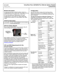
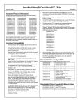
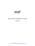
VersaMax Micro-20/40/64 PLC Ethernet Option Module GFK-2436G IC200UEM001 August 2013 Module Description Configuration This datasheet describes the Ethernet Option module for a VersaMax Micro-20, -40 or -64 PLC CPU. This module cannot be used with other types of VersaMax Nano or Micro PLCs. For more information about Option Modules, and about VersaMax Micro-20, -40 and -64 PLCs, please refer to the VersaMax Nano and Micro PLCs User’s Manual, GFK-1645J or later. Use of the Port Option module as Port 2 and the protocol selection must be set up in the configuration software. After making those selections, the communications parameters can also be configured. The option port should be configured for Ethernet. If the configuration and hardware do not match, the PLC logs a System Configuration Mismatch fault in the PLC Fault Table. The configuration options are: Ordering Information IC200UEM001 Protocol RJ 45, 10/100 Mbit Ethernet Communications module supporting SRTP SRTP Server Ethernet Option Module Ethernet Module IC200UEM001 can be used with a Micro-20, -40 or -64 -Point PLC to provide an Ethernet Port. Modbus TCP Client / Server* When installed on the Micro 20, 40 or 64 PLC, the Ethernet Port Option Module becomes Port 2. It supports the following communications protocols: SRTP, Modbus Server and client (separate download) and pass- through port (separate download). Protocol options are available online at www.ge-ip.com/support. FCC and ICES Requirements for the US and Canada This device complies with Part 15 of the FCC Rules. Operation is subject to the following two conditions: (1) this device may not cause harmful interference, and (2) this device must accept any interference received, including interference that may cause undesired operation. Note: This equipment has been tested and found to comply with the limits for a Class A digital device, pursuant to Part 15 of the FCC Rules. These limits are designed to provide reasonable protection against harmful interference when the equipment is operated in a commercial environment. This equipment generates, uses, and can radiate radio frequency energy and, if not installed and used in accordance with the instructions, may cause harmful interference to radio communications. Operation of this equipment in a residential area is likely to cause harmful interference in which case the user will be required to correct the interference at his own expense. Pass-Through or Tunneling Note: This Class A digital apparatus complies with Canadian ICES-003. * Changes or modifications not expressly approved by GE could void the user's authority to operate the equipment. 1 Parameters Value Port Mode SNP Port Type Slave Data Rate 19.2, 38.4 or 175.0 kbps (default) Flow Control None Parity Odd (default), Even, None Stop bits 1 (default) or 2 Time Out Long Turnaround Time 0 Port Mode RTU Port Type Slave Data Rate 19.2, 38.4 or 175.0 kbps (default) Flow Control None Parity Odd (default), Even, None Station Address Valid range 0–247. Default=1 Modbus/TCP Client Support (Refer to the VersaMax Nano and Micro PLCs User’s Manual, GFK-1645J or later.) Disabled (default) or Enabled. Port Mode Serial I/O Data Rate 19.2, 38.4 or 175.0 kbps (default) Flow Control None Parity Odd (default), Even, None Stop bits 1 (default), or 2 Bits/Characters 7 or 8 Enabling Modbus/TCP Client Support sets the %I00488 status bit ON. Station Address Valid range: (Byte 1 to Byte 8) 0–F. Default=0 When the Ethernet Option Module is configured for Modbus/TCP Client, the configured Sequence Number and Command Data addresses should not overlap or conflict with any other variables used in the logic. These addresses are reserved exclusively for communications between the CPU and Ethernet module when initiating Modbus TCP commands. GFK-2436G VersaMax Micro-20/40/64 PLC Ethernet Option Module IC200UEM001 August 2013 Installation Instructions Setting the Temporary IP Address Power to the VersaMax Micro PLC must be turned off when installing or removing Option Modules. First, set up a temporary IP address using Proficy Machine Edition Logic Developer. 1. 1. Open your project. 2. Click on Utility on the Navigator box. 3. Click on Set Temporary IP Address. 4. Enter a Temporary IP address and MAC address for the Ethernet module (MAC address is located on the front of the Ethernet module). The IP address is only temporary and when Micro PLC is power-cycled, the IP address will be lost. 5. Once Set IP is clicked you will get confirmation that temporary IP has been set. At this point you can go on-line with Machine Edition via Ethernet and do any function that you would do with a serial connection. Remove the two doors shown below, by pressing downward on the latches and lifting them away from the module. Press Down Latch and Remove These Two Doors 2. If a port-type Option Module is being installed, orient the connector on the Option Module with the connector in the Micro PLC. Be careful to avoid contact with the exposed components in the module. Connector for Option Module Setting the Permanent IP Address 1. Go to C:/ Prompt on your computer and type: Ping [IP address] and press the Enter key. (This step is required to “establish” the ARP table by creating an entry in the table.) The address pinged should reply with Pinged data. (example c:/ Ping 10.10.0.5 and return data) Screws for Option Module 2. Type: arp –a (space between p and –a). You should see at least one entry in the ARP table. (example c:/ arp –a) 3. Type: arp –s [IP address, including dots] [MAC Address of the Ethernet module, including dashes]. You will not see any reply on the screen. (example c:/ arp –s 10.10.0.5 00-20-4a-ff-ff-e9) 3. Press the Option Module downward until it clicks into place. 4. Install the screws provided with the Option Module into the corners indicated above. Connector for Memory Pack Module 4. Type: telnet [IP address] 1 (leave space between IP address and 1) and press the Enter key. You will be prompted that the connection failed. This is normal. (example c:/ telnet 10.10.0.5 1) Port Connector 5. Type: telnet [IP address] 9999 (leave space between IP address and 9999) and press the Enter key. You will be prompted to Press Enter to go into Setup Mode. You have two seconds to press the Enter key again. If you get the message “Connection to host lost”, re-enter telnet [IP address] and press the Enter key twice to get to the setup screen. (example c:/ telnet 10.10.0.5 9999) 5. If a Memory Pack Module is being installed, orient the connector on the back of the Memory Pack Module with the connector on the Micro PLC or port-type Option Module. Press the Memory Pack down until it clicks into place. Press 1 to change IP address (Enter the desired IP address) and Net Mask 6. Install the protective cover(s). If only the Memory Pack Module is used, both covers may be installed. If a port module is used, the right hand cover is not installed and the port connector remains accessible. Press 2 to change Serial Settings. For best performance, set the baud rate to 175000. Setting should be Mode#1, RS232 175000, 8, 0, 1. Port 2 needs to be configured with Proficy Machine Edition to match these settings. Machine Edition should configure Port 2 for Ethernet and baud rate of 175000. Setting the IP Address Key items to remember when setting the IP address on the VersaMax Micro Ethernet module (IC200UEM001): ▪ ▪ ▪ When complete, press S to save to the Ethernet module. You will see a prompt that informs you Parameters saved, Display will Restart…. and then Connection to host lost. The data is now stored in the internal Flash of the IC200UEM001. You can change the settings by repeating the above steps. When connecting via Ethernet point- to-point, a crossover cable is required. IP address setting must be saved to the Flash on the Ethernet module or it will be lost during power cycle. The second port of the Micro PLC must be configured for Ethernet. 2 VersaMax Micro-20/40/64 PLC Ethernet Option Module GFK-2436G IC200UEM001 August 2013 Settings are now complete. Verify that Port 2 matches above configuration by connecting to the Micro PLC serial port and checking hardware configuration. To download Ethernet drivers: 1. Open the PumpKIN Utility. Downloading Ethernet Drivers The Ethernet drivers for the Ethernet Option Module are downloaded from www.ge-ip.com/support. Files and passwords are: Upgrade Kit for Release 3.3 Destination Password GE Intelligent Platforms SRTP 82A1587-MS10-000-B1 G5 Modbus TCP (Client and Server in single firmware)* 82A1588-MS10-000-B1 G5 Tunneling or Pass Thru** 82A1589-MS10-000-B1 G5 Function 2. Click on Put File and Local file to be downloaded (Modbus_TCP). 3. Enter password G5 (case sensitive, must be upper case G) in Remote file. For Remote host, enter the IP address of the Micro PLC (for example: 10.10.0.2). 4. When the file is downloaded the utility will respond with the following: * When the Ethernet option module is loaded with the Modbus image it cannot communicate with PME. **When the Tunneling image is loaded, the 175000 baud rate is configurable only when the CPU Performance parameter is set to High in Telnet Configurator. The CPU Performance parameter is available in the Expert Setting menu. Downloading is done using the PumpKIN utility, which is included. To download a driver, perform the following procedure. Only one driver can be present at one time. After the driver has been downloaded you will have to reconfigure the port using Telnet. 3 GFK-2436G VersaMax Micro-20/40/64 PLC Ethernet Option Module IC200UEM001 August 2013 5. 6. When the transfer is accomplished, go back to Telnet and configure the settings by following the procedure listed under Setting the Permanent IP Address on page 2. Refer to GFK-1645 for more information on configuration options. Status LEDs Settings are now complete. Verify that Port 2 matches above configuration by connecting to the Micro PLC serial port and checking hardware configuration. Link LED (Amber) Solid Amber: Connection to Micro PLC established and network is connected Activity (Green) Flashing Green when there is any activity on the network Status (Red) OFF: No errors Red ON: Duplicate IP address present or network controller error Security Settings Note: This information replaces the “Security Settings for the Ethernet Option Module” section in chapter 14 of GFK-1645J and will be included in the next revision of that manual. Red BLINK (2x/sec): No DHCP response or Setup menu active Security settings are provided to prevent unauthorized access to the Ethernet Option Module configuration mode. Five security parameters are supported for the Ethernet Option Module (firmware versions 3.3 and later). Module Specifications Security settings are provided for the three protocols: SNP/SRTP, Modbus TCP and Tunneling. These parameters allow you to configure the Telnet password, enable the required ports and disable the unused ports Note: We strongly recommend configuration of the Telnet password and closing the unused ports. This will reduce the exposure to security threats. These ports are disabled by default. A port must be enabled if the application needs a service associated with that port. Processor Speed DSTni-EX CPU, 48MHz Memory 256 kByte RAM, 512 kByte FLASH Connection Type RJ 45 10Base-T/100Base-TX Ethernet Entity Type Client/Server Bus Speed 10/100Mbaud Protocols Supported Number of Connections Supported SRTP (preloaded) Modbus TCP Server and Client (optional) Tunneling (optional) Supports up to 8 Modbus TCP/IP server channels. If client configured then 1 client and 7 server channels supported. Supports 4 SRTP server channels Supports 1 connection for Tunneling Mode Full Duplex For firmware upgrade, the TFTP Download must be enabled. For connection with Device Installer, Port 77FE must be enabled. For use as web server the configuration for Web Server must be enabled. By default Simple Network Management Protocol (SNMP) is Disabled. For Modbus TCP and SRTP protocols, these security settings options are in the "Network/IP Settings" menu. For Tunneling (Passthrough), these security settings are in "basic parameters/server" menu. The maximum password length is 16 characters. These characters can be alphanumeric or special characters. The password requires a minimum length of 8 characters. A password set on a particular protocol’s firmware remains in effect if the firmware is changed to that of a different protocol. For example, if a password is set on Modbus TCP firmware and later the firmware is changed to SNP/SRTP, the same password set on Modbus TCP firmware will still apply. 4 VersaMax Micro-20/40/64 PLC Ethernet Option Module GFK-2436G IC200UEM001 August 2013 Revision History Problems Resolved by this Revision IC200UEM001-AA Initial release. Compatible with VersaMax Micro 64 firmware release 3.5 and Proficy Machine Edition 5.5 IC200UEM001-AB Improved noise immunity. IC200UEM001-BC Added support for Modbus/TCP Client, enhanced data throughput (175,000bps), and 16-character password security. The Ethernet Option module would stop communicating and not respond to any command. This firmware release corrects this issue. New Features and Enhancements in this Revision Additional configuration options have been added to the Ethernet Option module. Firmware requirements: In the Telnet interface, a Security Settings group has been added to the configuration. These parameters allow you to configure the Telnet password, enable the required ports and disable the unused ports. Micro 20, 40 and 64 firmware versions 3.83 and later Ethernet Option Module firmware versions 2.0 and later. Programmer requirements: Proficy® Machine Edition Logic Developer PLC, version 6.0 or later. IC200UEM001-CC Labeling change. No changes to functions, features or compatibility. IC200UEM001-CD Firmware release 3.3 addresses issues listed below, and adds new security settings, listed in “New Features and Enhancements in this Revision.” Note: For additional details, see “Security Settings” on page 4. Telnet Configuration Note: The Ethernet option module will be power cycled and reset under the following conditions: Programmer and Micro CPU firmware requirements: same as version –BC. A connection to the Ethernet option module is established through TELNET and disconnected immediately. A connection to the Ethernet option module is established through TELNET, the configuration is edited, and you press "Q" (Quit without Save). Upgrades All previous versions can be upgraded to this firmware version. Once the module is upgraded to the 3.3 version, it will not support downgrade to older revision. Attempting to downgrade firmware may cause the module to fail permanently. Note: We strongly recommend configuration of the Telnet password and closing the unused ports. This will reduce the exposure to security threats. To reduce the risk of this being accidentally or maliciously used, to permanently disable the module, GE IP strongly recommends that TFTP be disabled by the user, and only enabled via (password-protected) telnet when a firmware update is required. Functional Compatibility The default data rate with Ethernet option module firmware version 2.0 is 175000 bps. Micro firmware versions below 3.83 do not support 175000 bps. If firmware version 2.0 is to be used with Micro firmware versions prior to 3.83, the data rate on Ethernet Option module should be changed to 38400 bps or less, as per the requirement. 5 VersaMax Micro-20/40/64 PLC Ethernet Option Module GFK-2436G IC200UEM001 August 2013 Port Number Serial IO Configurable Parameters The setting represents the source port number in TCP connections. It identifies the channel for remote initiating connections. The range is 1-65535, except for the following. Baud Rate The supported baud rates are 19200, 38400 and 175000. This baud rate should match the baud rate of the configuration software. Port numbers Reserved for 1-1024 Reserved (well known ports) 9999 TELNET Setup 14000-14009 Reserved for Redirector The following table displays available I/F Mode options: 30704 Reserved (77F0h) Note: All bit positions in the table that are blank represent “don’t care” bits for that particular option, which can be set to either a 0 or 1 value. Only RS-232C is supported and hence Bit 0 and Bit 1 always should be zeros. If you attempt to select an I/F Mode bit that pertains to RS-422/485 settings, the WARNING: RS422/485 I/F Modes Not Supported” message displays. 30718 Reserved (77FEh) I/F Mode (Interface Mode) The Interface (I/F) Mode is a bit-coded byte entered in hexadecimal notation. I/F Mode Option 7 6 5 4 3 2 RS-232C 7 Bit 8 Bit 1 0 0 0 Warning Do not use the reserved port numbers for this setting because incorrect operation may result. 1 0 Connect Mode 1 1 Connect Mode defines how the unit makes a connection, and how it reacts to incoming connections over the network. No Parity 0 0 Even Parity 1 1 Connect Mode Option 0 1 a) Incoming Connection Odd Parity 1 Stop bit 0 1 2 stop Bit 1 1 Common Interface Mode Settings 7 6 5 Never accept Incoming 0 0 0 Always Accept 1 1 0 4 3 1 0 0 0 1 b) Response Binary Hex Nothing (quiet) 0 RS-232C, 8-bit, No Parity, 1 stop bit 0100 1100 4C 1 RS-232C, 7-bit, Even Parity, 1 stop bit 0111 1000 78 Character response (C = Connect, D= disconnect, N = Unreachable) Common I/F Mode Setting 2 c) Active Startup With any character Flow Flow control sets the local handshaking method for stopping serial input/output. This should be set to zero always. 0 Remote IP Address This setting specifies the remote IP address through which the communication needs to be established. Remote Port The setting represents the destination port number in TCP connections. It is the number that identifies the channel for remote initiating connections. Note: See the reserved port numbers from the table specified in Port Number section. DisConn Mode: Set to zero. 6 FlushMode: Set to zero. DisConnTime: Set to zero. SendChar 1: Set to zero SendChar 2: Set to zero. VersaMax Micro-20/40/64 PLC Ethernet Option Module GFK-2436G IC200UEM001 August 2013 Examples To change the Serial Parameter Settings in SRTP Protocol: User entries are shown in bold. Connect PLC with IC200UEM001 on port2 in the Network. To configure the Modbus/TCP Client in IC200UEM001 through TELNET: For this example, the current protocol is SRTP and serial settings are 175000,8,O,1. The following procedure explains how to change the existing serial parameters to 38400,8,N,2 Connect PLC with IC200UEM001 on port2 in the Network. For this example, the IP address of the IC200UEM001 is 10.10.0.5 For this example, the IP address of the IC200UEM001 is 10.10.0.5 Load the Ethernet Option Module firmware upgrade kit, 82A1588-MS10-000-B1 Type TELNET 10.10.0.5 9999 at command prompt. Configure the parameters of the Ethernet Option Module as follows: Type TELNET 10.10.0.5 9999 at command prompt. Follow the below procedure to configure the parameters of the Ethernet Option Module. MAC address XXXXXXXXXXXX Software version 01.8 (090618) XPTEX Modbus/TCP to RTU Bridge Press Enter to go into Setup Mode MAC address XXXXXXXXXXXX VMSE GE Intelligent Platforms SNP. Software version 02.5 (090526) XCARD 1) Network/IP Settings: Press Enter to go into Setup Mode IP Address .................... 10.10.0.5 Model: Device Server OEM (Firmware Code:G5) Default Gateway ……….10.10.0.1 Modbus/TCP to RTU Bridge Setup Netmask ..............……...255.000.000.000 1) Network/IP Settings: 2) CH1 Serial & Protocol Settings: IP Address .......................10.10.0.5 Default Gateway ……… Protocol Mode .............. 10.10.0.1 Mode#1 SRTP Ethernet to Serial SNP Slave Netmask .........................255.000.000.000 Serial Interface ....................175000,8,O,1 SNMP is enabled T1, Turn-Around Delay ...... 00002 msec 2) Serial & Mode Settings: T2, ACK/NAK Timeout ........ 09000 msec Protocol ........................Modbus/RTU,Slave(s) attached T3, Link Idle Timeout .......... 10000 msec Modbus/TCP Client .…..disabled T4, After Break Delay ......... 00400 msec Serial Interface ........…..38400,8,O,1 3) SNP ID to IP mapping table (not used in this mode) 4) Advanced Modbus Protocol settings: D)efault settings, S)ave, Q)uit without save Slave Addr/Unit Id Source .. Modbus/TCP header Select Command or parameter set (1..3) to change: Press 2 Modbus Serial Broadcasts .. Disabled (Id=0 auto-mapped to 1) 2) CH1 Serial & Protocol Settings: Mode#1 SRTP Ethernet to Serial SNP Slave MB/TCP Exception Codes ..... Yes (return 00AH and 00BH) Mode#2 Serial SNP Master to Remote VMSE Char, Message Timeout ...... 00050msec, 05000msec D)efault settings, S)ave, Q)uit without save Select desired operating mode (1) Enter serial parameters (175000,8,O,1): 38400,8,N,2 New T1, Line Turn-Around Delay (2-1280 msec, 1ms resolution) (2) Press Enter Select Command or parameter set (1..4) to change: Press 2. Attached Device (1=Slave 2=Master) (1) Press Enter Modbus/TCP Client Enabled (N) Y New T2, ACK/NAK Timeout (50-12,950 msec, 50ms resolution) (9000) Press Enter Close Idle TCP sockets after (3-60 sec, 0=leave open) (10) Enter New T3, Link Idle Timeout (1000-60,000 msec, 250ms resolution) (10000) Press Enter Serial Protocol (1=Modbus/RTU 2=Modbus/ASCII) (1) Enter New T4, After <BREAK> Delay (5-1280 msec, 5ms resolution) (400) Press Enter Enter serial parameters (38400,8,O,1) 175000,8,O,1 After configuring all the parameters, Telnet will display the configured parameters. Press S to save the configuration to the Ethernet module. You will see the messages, Parameters saved, Restarting…. and then Connection to host lost. After configuring all the parameters, Telnet will display the configured parameters. Press S to save the configuration to the Ethernet module. You will see the messages, Parameters saved, Restarting…. and then Connection to host lost. 7