1
Pr.
Explanation
Settings
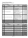
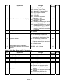
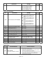
2-00
Source of Master Frequency
Command
2-01
Source of Operation
Command
2-02
Stop Method
2-03
PWM Carrier Frequency Selections
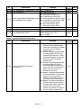
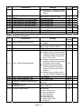
2-04
2-05
2-06
d5: Master Frequency operated by
RS-485 serial communication
interface and won’t record
frequency before power loss.
(won’t record the frequency of
power loss and it can do analog
overlap plus)
d0: Digital Keypad
d1: External terminals. Keypad
STOP/RESET enabled.
d2: External terminals. Keypad
STOP/RESET disabled.
d3: RS-485 serial communication
(RJ-11) .Keypad STOP/RESET
enabled.
d4: RS-485 serial communication
(RJ-11). Keypad STOP/RESET
disabled.
d0: STOP: ramp to stop; E.F.: coast
to stop
d1: STOP: coast to stop; E.F.: coast
to stop
d3: 3KHz
d7: 7KHz
d4: 4KHz
d8: 8KHz
d5: 5KHz
d9: 9KHz
d6: 6KHz
d10: 10KHz
d0: Enable forward/reverse
operation
d1: Disable reverse operation
d0: Decelerate to 0 Hz
d1: Coast to stop and display “EF”
Loss of ACI Signal
d2: Continue operation by last
frequency command
d0: Disable
Analog Auxiliary Frequency Operation d1: Enable + AVI
d2: Enable + ACI
Motor Direction Control
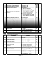
Factory
NOTE
Setting
d0
d0
d0
d10
d0
d0
d0
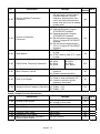
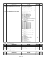
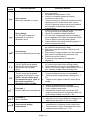
Group 3 Output Function Parameters
Pr.
3-00
Explanation
Settings
d0: analog frequency meter
d1: analog current meter
Analog Output Signal
a3-01 Analog Output Gain
3-02 Desired Frequency Attained
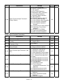
3-03
3-04
3-05
d1 to d200%
d1.0 to d400 Hz
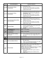
Terminal Count Value
Preliminary Count Value
Multi-Function Output Terminal 1
(Photocoupler Output)
Factory
NOTE
Setting
d0
d100
d1.0
d0 to d999
d0 to d999
d0
d0
d0: No Function
d1
English- 12