1
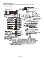
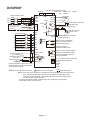
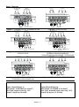
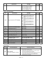
For VFDXXXSXXE
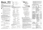
NPN (sink mode)
Braking resistor (optional)
select 80Ω 120W, 200Ω 120W
400Ω 120W
Jumper
Main Circuit Power
NFB
R/L1
S/L2
T/L3
Recommended Circuit
when power supply
is turned OFF by a
fault output
+1
E
R/L1
S/L2
T/L3
SA
MC
OFF
ON
MC
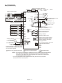
Factory default
Forward/Stop
Reverse/Stop
Reset
Multi-step 1
Multi-step 2
Multi-step 3
Comm. signal (sink)
Analog voltage 3
0~10VDC
Potentiometer Pot. 2
3K~5KΩ
Analog current 1
RB
RC
+2/B1
+17V
CPU
2.4Ω
17V
11V
M0
M2
NPN
M3
PNP
J2
GND
E
+10V 10mA
(MAX)
2 1
AVI 3
47KΩ
250Ω
GND
AC Motor
IM
3~
Grounding resistance
less than 100Ω
E
47ΩAFM
47KΩ
RA
RB
RC
M5
Factory default: output freq. (Pot.)
determined by the Potentiometer
on the control panel.
Main circuit (power) terminals
V/T2
W/T3
GND
M1
M4
B2
U/T1
Potentiometer(1KΩ)
+
-
Analog output
DC 0~10V
Factory default: indicate
output frequency
Multi-function indication
output contacts below
120VAC/24VDC 5A
Factory default:
indicates malfunction
Mo1
Multi-function Photocoupler
output below 48VDC 50mA
Factory default: Indicates
MCM during operation
RJ-11
6←1
Control circuit terminals
RJ-11 communication port with
RS-485 serial interface
1:17V
2:GND
3:SG4:SG+
Shielded leads
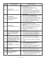
NOTE: Do not plug in a Modem or telephone line to the RS-485 communication
port, permanent damage may result. Terminal 1 & 2 are the power
sources for the optional copy keypad and should not be used while
using RS-485 communication.
* If it is single phase model, please select any of the two input power
terminals in main circuit power.
English- 4