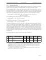
1
SeaShark
Detailed Design Document
Doc.Ref.: SHK-DDD-001 (Issue 2.0)
Date
: 17 June 1999
SeaShark Detailed Design Document
SHK-DDD-001 (Issue 2.0)
SeaShark
Detailed Design Document
Document No.: SHK-DDD-001
Issue No.:
2.0
Date:
17 June 1999
Distribution:
P. Goryl (ESRIN)
J-M. Melinotte (ESRIN)
Summary:
SeaShark will provide a capability to process, archive and disseminate data
acquired by the Seastar SeaWiFS and NOAA AVHRR sensors.
Authors:
C.L Aspell, S.J. Newby, J.E. Rickards, J. Mitchell, M.R. Lever,
J.W. Treloar (VEGA)
Signed:
[ S.J. Newby
]
Date:
Reviewed:
[ T. Stephens
]
Date:
Authorized:
[ C.P. Winder
]
Date:
Accepted:
[ ESA Responsible
]
Date:
page ii
SeaShark Detailed Design Document
SHK-DDD-001 (Issue 2.0)
Document Status Sheet
Issue
Draft A
Draft B
Draft C
Draft D
Issue 1.0
Issue 2.0
Date
17 Mar 97
31 Oct 97
13 Mar 98
30 Jun 98
17 Jun 99
Details
Document created
Updated to include Phase 2 & Phase 3 functionality
Update to include NOAA-KLM
Add all missing sections
Formal issue
Updated to describe support for HMF SeaWiFS HRPT
Author
C.L Aspell
J. Mitchell
M.R. Lever
M.R. Lever
S.J. Newby
page iii
SeaShark Detailed Design Document
Table of contents
SHK-DDD-001 (Issue 2.0)
Contents
Document Status Sheet ............................................................................................iii
Contents ...................................................................................................................iv
List of Tables ............................................................................................................ix
List of Figures ..........................................................................................................xi
Section 1 : INTRODUCTION .........................................................................................1
1.1 Purpose ................................................................................................................1
1.2 Scope ...................................................................................................................1
1.3 Definitions, Acronyms and Abbreviations ..........................................................1
1.4 References ...........................................................................................................2
1.5 Overview .............................................................................................................4
Section 2 : GENERAL DESCRIPTION .........................................................................5
2.1 Design Standards .................................................................................................5
2.2 Documentation Standards ...................................................................................5
2.3 Naming Conventions ...........................................................................................5
2.4 Programming Standards ......................................................................................6
2.5 Software Development Tools ..............................................................................11
Section 3 : PHYSICAL DESIGN ....................................................................................12
3.1 Introduction .........................................................................................................12
3.2 The Process Model ..............................................................................................12
3.3 Inter-Process Communication .............................................................................13
3.4 Inter-Process Messages .......................................................................................13
3.5 Archive Processing Chain ...................................................................................15
3.6 Distribution processing Chain .............................................................................18
3.6.1 Control of the Processing Chain .............................................................18
3.7 Directory Structure ..............................................................................................19
3.7.1 Top Level Directory Structure ................................................................19
3.7.2 Structure of the config Directory ............................................................20
3.7.3 Structure of the data Directory ...............................................................21
3.8 File Naming Conventions ....................................................................................24
3.9 System Start-up ...................................................................................................25
3.10 System Close Down ..........................................................................................25
3.11 Controlled Termination of Processes ................................................................25
page iv
SeaShark Detailed Design Document
Table of contents
SHK-DDD-001 (Issue 2.0)
3.12 Error Handling ..................................................................................................26
3.13 Tasks ..................................................................................................................26
3.13.1 Description ............................................................................................26
3.13.2 Storage ..................................................................................................27
3.13.3 Task Pool ..............................................................................................27
3.13.4 Individual Tasks ....................................................................................28
3.13.5 Task queues ...........................................................................................29
3.13.6 Task creation .........................................................................................29
3.13.7 Task example ........................................................................................30
3.14 Orders ................................................................................................................31
3.14.1 Terminology ..........................................................................................31
3.14.2 External Interfaces ................................................................................31
3.14.3 Physical Design ....................................................................................31
3.14.4 Errors ....................................................................................................32
3.14.5 Failed Order Directory ..........................................................................33
3.14.6 Multi-Order Files ..................................................................................33
3.15 Archive Products ...............................................................................................33
3.15.1 Physical Design ....................................................................................33
3.15.2 Errors ....................................................................................................34
Section 4 : PROCESSING INTERFACE ........................................................................36
4.1 Archive Processing ..............................................................................................36
4.1.1 Polling The Import Directories ...............................................................36
4.1.2 Viewing The Status Of Products .............................................................36
4.1.3 Counting The Products On The System .................................................37
4.1.4 Selecting Processing Steps .....................................................................37
4.1.5 Viewing The Image .................................................................................37
4.2 Order Processing .................................................................................................37
4.2.1 Polling The Import Directory .................................................................37
4.2.2 Processing ...............................................................................................37
4.2.3 Sending Status Files ................................................................................37
4.2.4 Purging The Order Store .........................................................................37
4.2.5 The Operator Interface ............................................................................38
4.2.6 Counting The Orders On The System ....................................................38
4.2.7 Viewing The Status Of Orders ................................................................38
4.2.8 Initiating Order Processing .....................................................................39
4.2.9 Viewing Full Order Details .....................................................................39
4.2.10 Entering New Orders ............................................................................39
page v
SeaShark Detailed Design Document
Table of contents
SHK-DDD-001 (Issue 2.0)
4.3 Immediate and Batch Processing ........................................................................40
Section 5 : FILE FORMATS ...........................................................................................41
5.1 AVHRR HRPT Product .......................................................................................41
5.1.1 AVHRR HRPT Level 0 File Formats .....................................................41
5.1.2 AQTIM.DAT File Format .......................................................................42
5.2 SeaWiFS HRPT Product .....................................................................................42
5.3 SeaWiFS HRPT Level 0 File Formats ................................................................43
5.4 SeaWiFS and AVHRR Level 1 Archive Product ................................................44
5.4.1 Imagery File ............................................................................................44
5.4.2 Navigation Data File ...............................................................................47
5.4.3 Land Sea Mask File ................................................................................49
5.4.4 Coastline File ..........................................................................................50
5.4.5 Calibration Data File (AVHRR Only) ....................................................52
5.4.6 Quicklook Product ..................................................................................53
5.4.7 Postscript Quicklook File .......................................................................53
5.4.8 Catalogue Entry File ...............................................................................55
5.4.9 Acquisition Details File ..........................................................................55
5.4.10 Orbit Data File ......................................................................................55
5.4.11 ArchiveTape Index File .........................................................................55
5.5 Fast Delivery Product ..........................................................................................56
5.5.1 Image File ...............................................................................................56
5.5.2 Description File ......................................................................................56
5.6 Level 1 Distribution Product ...............................................................................58
5.6.1 IMAGE File ............................................................................................58
5.6.2 LEADER File .........................................................................................58
5.6.3 NULL_VDF File ....................................................................................58
5.6.4 TRAILER File ........................................................................................58
5.6.5 VDF File .................................................................................................58
5.6.6 Distribution Tape Index File ...................................................................58
5.6.7 Order Status file ......................................................................................58
5.6.8 Order file .................................................................................................59
5.7 Level 2 Distribution Product ...............................................................................61
5.7.1 IMAGE File ............................................................................................62
5.7.2 LEADER File .........................................................................................62
5.7.3 NULL_VDF File ....................................................................................62
5.7.4 TRAILER File ........................................................................................62
5.7.5 VDF File .................................................................................................62
page vi
SeaShark Detailed Design Document
Table of contents
SHK-DDD-001 (Issue 2.0)
5.7.6 Distribution Tape Index File ...................................................................62
5.7.7 Order status file .......................................................................................63
5.7.8 Order file .................................................................................................63
5.8 Report File ...........................................................................................................63
5.9 Configuration File Format ...................................................................................66
5.10 Log File Format .................................................................................................67
5.11 MEDIA FORMATS ..........................................................................................68
5.11.1 Archive Tape .........................................................................................68
5.11.2 Distribution Tape ..................................................................................70
Section 6 : PROCESSING STEPS ..................................................................................72
6.1 Import ..................................................................................................................72
6.1.1 HRPT import ..........................................................................................72
6.1.2 Level 0 import .........................................................................................73
6.2 The Navigation Process .......................................................................................74
6.2.1 Locating the satellite’s position, attitude and viewing geometry ...........74
6.2.2 Generating the navigation grid ...............................................................75
6.2.3 Geographic location to pixel position .....................................................76
6.2.4 Navigation data summary .......................................................................77
6.2.5 Coastline adjust .......................................................................................77
6.3 Level1 ..................................................................................................................78
6.4 Archive ................................................................................................................80
6.5 Delete ..................................................................................................................80
6.6 Retain ..................................................................................................................80
6.7 Orbit Stitching .....................................................................................................80
6.8 Retrieve ...............................................................................................................81
6.9 Generate ..............................................................................................................81
6.10 AVHRR Distribution Product OverView ..........................................................83
6.11 Calibration of visible AVHRR channels ...........................................................83
6.11.1 Even numbered satellites ......................................................................83
6.11.2 Odd numbered satellites .......................................................................84
6.12 Calibration of Thermal AVHRR channels ........................................................84
6.12.1 Calculation of Spectral Radiance .........................................................84
6.13 NOAA-KLM and the AVHRR/3 type instrument .............................................85
6.13.1 NOAA-KLM calibration .......................................................................86
6.13.2 Changes to the IMAGE file ..................................................................86
page vii
SeaShark Detailed Design Document
Table of contents
SHK-DDD-001 (Issue 2.0)
6.13.3 Changes to the LEADER file ................................................................88
6.14 SeaWiFS Distribution Products ........................................................................88
6.15 Distribute ...........................................................................................................88
6.16 Delete ................................................................................................................88
Section 7 : COMPONENTS .............................................................................................89
7.1 Graphical User Interface .....................................................................................89
7.2 List of Modules ...................................................................................................90
7.2.1 Processes .................................................................................................90
7.2.2 Programs .................................................................................................90
7.2.3 Classes ....................................................................................................91
7.3 Scripts ..................................................................................................................104
7.4 Processes .............................................................................................................104
7.4.1 Media Handler ........................................................................................104
7.5 Programs .............................................................................................................106
7.5.1 Ingest_Climatology ................................................................................106
7.5.2 Ingest_Meteorology ................................................................................106
7.6 Scripts ..................................................................................................................106
7.6.1 CleanDataAreas ......................................................................................106
7.6.2 CreateInstallTape ....................................................................................107
7.6.3 Install ......................................................................................................107
7.6.4 SeaSharkBuildComms ............................................................................107
7.6.5 SeaSharkBuildDir ...................................................................................107
7.6.6 TidySeaShark ..........................................................................................107
7.6.7 cshrc.SeaShark ........................................................................................107
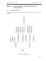
Appendix A : SOURCE DIRECTORY STRUCTURE AND DESCRIPTION ..........A-1
A.1 Class interconnection .........................................................................................A-1
A.2 Source Directory Structure .................................................................................A-4
page viii
SeaShark Detailed Design Document
List of tables
SHK-DDD-001 (Issue 2.0)
List of Tables
Table 2-1 Development Area Directory Structure ............................................................5
Table 2-2 Directory Structure of $SEASHARKHOME ....................................................5
Table 2-3 C++ Coding Rules .............................................................................................7
Table 2-4 C++ Coding Recommendations ........................................................................9
Table 2-5 C++ Coding Portability Recommendations ......................................................11
Table 3-1 Inter-Process Messages .....................................................................................14
Table 3-2 Inter-Process Message Format ..........................................................................15
Table 3-3 Steps in the Archive processing chain ..............................................................17
Table 3-4 Steps in Distribution processing chain ..............................................................18
Table 3-5 SeaShark Directory Content ..............................................................................20
Table 3-6 Content of the data Directory top level .............................................................22
Table 3-7 Content of the data Directory ............................................................................23
Table 3-8 Task Pool data structure ....................................................................................27
Table 3-9 Task data structure ............................................................................................28
Table 3-10 Task Form data structure .................................................................................28
Table 3-11 Task Queue Store data structure .....................................................................29
Table 3-12 Selected task member functions ......................................................................30
Table 3-13 Order errors .....................................................................................................32
Table 3-14 Processing Errors ............................................................................................34
Table 5-1 AQTIM.DAT Format ........................................................................................42
Table 5-2 Format of the HMF SeaWiFS HRPT Image Data Record ................................43
Table 5-3 Files in a Level 1 Archive Product ....................................................................44
Table 5-4 Format of the SeaWiFS Level 1 Image Data Record ........................................44
Table 5-5 Format of the SeaWiFS Image_data Structure ..................................................45
Table 5-6 Format of the AVHRR Level 1 Image Data Record .........................................46
Table 5-7 Format of the AVHRR Image_data Structure ...................................................46
Table 5-8 Format of the Navigation Data ..........................................................................47
Table 5-9 Format of the Grid Dimensions structure .........................................................48
Table 5-10 Format of the Grid Row structure ...................................................................48
Table 5-11 Format of the Grid Point Values structure ......................................................49
Table 5-12 Format of the Land Sea Mask Record .............................................................50
Table 5-13 Format of the Classification Flags structure ...................................................50
Table 5-14 Format of the Coastline File ............................................................................50
Table 5-15 Format of the Segment structure .....................................................................51
Table 5-16 Format of the Earth Extent structure ...............................................................51
Table 5-17 Format of the Image Extent structure ..............................................................51
Table 5-18 Format of the Coastline Point structure ..........................................................52
Table 5-19 Format of the Calibration Data Header record ................................................52
Table 5-20 Format of the Calibration Data Record ...........................................................52
Table 5-21 Archive Tape index file header record ............................................................55
Table 5-22 Archive Tape index file data record ................................................................55
Table 5-23 Format of the FDP Description File ................................................................56
Table 5-24 Order status file data Record ...........................................................................58
Table 5-25 Order file data Record .....................................................................................59
Table 5-26 Tape distribution index file header Record .....................................................62
Table 5-27 Tape distribution index file data record ..........................................................62
Table 5-28 Format of the First Header Line of a Report ...................................................63
Table 5-29 Format of the Second Header Line of a Report ..............................................63
page ix
SeaShark Detailed Design Document
List of tables
SHK-DDD-001 (Issue 2.0)
Table 5-30 Format of the Report Line of the Acquisition & Archiving Report ................64
Table 5-31 Format of the Report Line of the Distribution Report ....................................65
Table 5-32 Format of the Report Line of the Media Report .............................................66
Table 5-33 Archive Tape Format ......................................................................................68
Table 5-34 Archive Tape – Label Format .........................................................................69
Table 5-35 Archive Tape – Directory Format ...................................................................69
Table 5-36 Format of the Archive Tape Directory Entry ..................................................70
Table 5-37 Archive Tape – Product Files ..........................................................................70
Table 5-38 Distribution Tape Format ................................................................................71
Table 6-1 Distribution product types – AVHRR ...............................................................81
Table 6-2 Distribution product types – SeaWiFS ..............................................................82
Table 6-3 Extract from the (NOAA-KLM) FILE DESCRIPTOR RECORD ...................87
Table 7-1 SeaShark Processes ...........................................................................................90
Table 7-2 Classes Used by SeaShark ................................................................................91
Table 7-3 Scripts used by SeaShark ..................................................................................104
Table 7-4 Request Structure ..............................................................................................105
page x
SeaShark Detailed Design Document
List of figures
SHK-DDD-001 (Issue 2.0)
List of Figures
Figure 3-1 Process Model................................................................................................... 12
Figure 3-2 Archive processing chain.................................................................................. 16
Figure 3-3 Distribution processing chain ........................................................................... 18
Figure 3-4 Top Level Directory Structure.......................................................................... 20
Figure 3-5 Structure of the data Directory.......................................................................... 21
Figure 3-6 Structure of the telecom.out Directory ............................................................. 24
Figure 5-1 Grid Dimensions structure ................................................................................ 49
Figure 5-2 Postscript Quicklook File ................................................................................. 54
Figure 6-1 An example of an interpolated navigation grid ................................................ 75
Figure 6-2 Graphical representation of an affine coefficient matrix .................................. 76
Figure A-1 Image hierarchy ............................................................................................... A-1
Figure A-2 BrouwerOrbitElement hierarchy...................................................................... A-2
Figure A-3 CEOSGenericRecordID hierarchy................................................................... A-2
Figure A-4 QueueHandler hierarchy .................................................................................. A-2
Figure A-5 TransformCoefficients hierarchy ..................................................................... A-2
Figure A-6 Product hierarchy ............................................................................................. A-3
Figure A-7 ScanLineField hierarchy .................................................................................. A-4
Figure A-8 Sub directories of top-level source directory ................................................... A-5
Figure A-9 Sub directories of top-level source directory (continued)................................ A-6
Figure A-10 Catalogue sub directories............................................................................... A-7
Figure A-11 Interface sub directories................................................................................. A-7
Figure A-12 Processing_Steps sub-directories................................................................... A-8
Figure A-13 Product sub directories................................................................................... A-9
Figure A-14 orbit_data sub-directories .............................................................................. A-10
Figure A-15 Processes sub-directories ............................................................................... A-10
page xi
SeaShark Detailed Design Document
INTRODUCTION
1
INTRODUCTION
1.1
Purpose
SHK-DDD-001 (Issue 2.0)
To document the detailed design of the SeaShark software.
This document is intended to be read by parties interested in the software development of SeaShark, including:
• ESRIN, which wishes to ensure that the software will encompass a complete and consistent
set of functions;
• VEGA, the developer of SeaShark, which wishes to ensure that the scope of the software is
well-defined and that the software will be testable.
1.2
Scope
The SeaShark project will develop software to provide a capability for the processing, archiving and dissemination of data from the SeaStar and NOAA satellites. The software will be
installed at several acquisition stations of the European Co-ordinated Tiros Network; it will
provide an environment in which the data processing can be easily carried out by trained operators on a regular basis.
1.3
Definitions, Acronyms and Abbreviations
This section lists the definitions of all terms, acronyms and abbreviations, or refer to other documents where the definitions can be found.
Term
ADD
AQTIM
APT
AVHRR
BPI
CCT
CEOS
DCW
ECTN
EPOORD
ESA
ESRIN
FDP
GIF
GUI
HRPT
IDL
Definition
Architectural Design Document
AcQuisition TIMe
Automatic Picture Transmission
Advanced Very High Resolution Radiometer
Bits Per Inch
Computer Compatible Tape
Committee on Earth Observation Satellites
Digital Chart of the World
ESRIN Co-ordinated TIROS Network
Earthnet Programme Office
European Space Agency
European Space Research INstitute
Fast Delivery Product
Graphics Interchange Format
Graphical User Interface
High Resolution Picture Transmission
Interactive Data Language (visualisation software)
Table 1-1
Definition of Terms
Page 1
SeaShark Detailed Design Document
INTRODUCTION
Term
LAC
MMDD
NASA
NDVI
NOAA
OD
OSC
OSF
PML
SeaWiFS
SCSI
SHARK
SHARP
SIUF
SST
TIROS
URD
SRD
Definition
Local Area Coverage
Multi-Mission Data Dissemination
National Aeronautics and Space Administration
Normalised Difference Vegetation Index
National Oceanic and Atmospheric Administration
Optical Disc
Orbital Sciences Corporation
Open Software Foundation
Plymouth Marine Laboratory (UK)
Sea-Viewing Wide Field-of-View Sensor
Small Computer Systems Interface
Station HRPT Archiving and Reprocessing Kernel
Standard HRPT Archive and Request Product
SeaWiFS Inventory Update Format
Sea Surface Temperature
Television and Infra-Red Observation Satellite
User Requirements Document
Software Requirements Document
Table 1-1
1.4
SHK-DDD-001 (Issue 2.0)
Definition of Terms
References
The following is a list of documents with a direct bearing on the content of this report. Where
referenced in the text, these are identified as [n], where n is the number in the list below.
[1]
ESRIN Invitation To Tender AO/1-2489/HGE/93, Development of the SeaShark Software System for the SeaWiFS, European Data Information System (SEDIS), 10 June
1993.
[2]
VEGA Group PLC Company Quality Manual, QA.STN.009, Current issue
[3]
ESA Software Engineering Standards, ESA PSS-05-0, Issue 2, February, 1991
[4]
SeaShark User Requirements Document, SHK.URD.002, Issue 2, 13 January 1994.
[5]
SeaShark Project Development Plan, SHK.PLN.006, Issue 1, 21 February, 1997.
[6]
SeaShark Software Requirements Document, SHK.SRD-1.0, 10 March, 1994.
[7]
SeaShark L2 Processor and Upgrade Software Requirements Document, SHK.SRD.002,
30 April, 1997.
[8]
SeaShark Architectural Design Document, SHK.ADD-1.0, 20 May, 1994.
[9]
SeaShark SeaWiFS Level 2 Processing Architectural Design Document, SHK.ADD.002,
23 July, 1997.
[10] SeaShark Software User Manual, SHK-SUM-3.0, 16 December, 1997.
[11] SeaShark Software Transfer Document, SHK.STD.003, 18 December, 1997.
Page 2
SeaShark Detailed Design Document
INTRODUCTION
SHK-DDD-001 (Issue 2.0)
[12] ESA PSS-05-03 Issue 1: Guide to Software Requirements Definition Phase, ESA BSSC,
October 1991.
[13] Object-Oriented Design, G. Booch, Benjamin/Cummings, 1991.
[14] Ground Location of Satellite Data, Puccinelli, Photogrammatic Engineering and Remote
Sensing, Vol. 4, #4, April 1976.
[15] Digital Chart of the World, VPFVIEW Users Manual for DOS, Version 1.0, July 1992
[16] Digital Chart of the World, Vector Product Standard, Defense Mapping Agency, November 1990.
[17] Digital chart of the World, DCW Product Specification, Defense Mapping Agency,
November 1990.
[18] Solaris 2.0 Transition Planning Guide for Application Developers, Sun Microsystems
Inc., 1991.
[19] Pipeline to Solaris 2.0. A Porting Reference Guide for Software Developers, Sun Microsystems Inc., 1991.
[20] SHARP-1 Technical Specification of CCT Format, Release 1.1, ESA EPO, February
1991.
[21] SHARP-2 Technical Specification of Format, Release 1.0. ESA-EPO, March 1992.
[22] Bad Line Philosophy, ESRIN DPE/OT/JMM/93-001, Issue 1.4.
[23] OSF/Motif Style Guide, Version 1, Open Systems Foundation, 1990.
[24] EO Formatting System, Instrument Data Product Format, SeaWiFS LAC 1A, EOFSIDF-002-TN-2.1, 4 April, 1995.
[25] EO Formatting System, Instrument Data Product Format, SeaWiFS LAC 1B, EOFSIDF-003-TN-1.1, 9 August, 1995.
[26] EO Formatting System, Inventory Exchange Format, SeaWiFS Inventory Update File
(SIUF) Specification, EOFS-IEF-002-TN-2.2, 2 March, 1995.
[27] SeaShark System Specifications, Annex A, DPE/OT/JMM/93-001 Issue 1.4.
[28] SeaShark Software Data Format Definitions, SHK.REP.003-1.0, 9 September 1994.
[29] SeaShark System Specifications, Reporting, DPE/OT/JMM/93-001 Issue1.4
[30] SeaShark System Specifications Annexes, SeaS-GS-AN-00, Issue 1.0, 20 April 1993.
[31] Programming in C++ Rules and Recommendations, Ellemtel document M900118, dated
27-04-1992.
[32] Effective C++, Scott Meyers, Addison Wesley, ISBN 0-201-56364-9.
[33] The Annotated C++ Reference Manual, M.A.Ellis & B.Stroustrup, published by Addison-Wesley, 1990.
[34] Two Line Element Set Format Description, SPACECOM/NASA, date unknown.
[35] Tbus format, APT Information Note, February 1981.
[36] EPOORD/Ground Station Interface Specification, SH3-EPO-SER-00-006, Issue 3.2,
26 June, 1995.
[37] Orbit Stitching Philosophy, ESRIN fax, 27 March, 1995.
Page 3
SeaShark Detailed Design Document
INTRODUCTION
SHK-DDD-001 (Issue 2.0)
[38] SeaStar Spacecraft L-Band Downlink to Receiving Stations Interface Control Document,
Orbital Sciences Corporation, 22 April, 1996.
[39] NOAA Technical Memorandum NESS-107 Rev. 1
[40] Frame Formatter (Level 0) output file format, version 1.1, by Frederick S. Patt, NASA,
April 16, 1993, updated by B. Franz, September 1997.
[41] Tools.h++ Foundation Class Library for C++ Programming, Version 7, Rogue Wave
Software Inc., 1996.
[42] SeaShark Instrument Data Product Format – FDP Generic Format, SHK.ICD.003,
27 November, 1996.
[43] SeaShark Instrument Data Product Format – SeaWiFS Flexible Format, SHK.ICD.004,
28 October, 1997.
[44] SeaShark SeaWiFS Level 2 Processing – Guide to Products, SHK.GTP.001, 9 February,
1998.
[45] HMF SeaWiFS HRPT Data Format, SHK.ICD.005, 17 June, 1999.
1.5
Overview
The document follows the guidelines laid down in the ESA Software Engineering Standards
PSS-05-02 [3]. After this introduction, the document is divided into a number of major sections which are briefly described below:
2. GENERAL DESCRIPTION
This section outlines the standards which will apply to all software developed
within the project.
3. PHYSICAL DESIGN
This section describes the physical design of SeaShark, i.e. how the system is
divided into physical design elements, such as processes, and how those processes communicate with each other.
4. PROCESSING INTERFACE
Defines how SeaShark executes processing tasks. Some are automatic, others
require operator intervention.
5. FILE FORMATS
Defines the file formats used within SeaShark.
6. PROCESSING STEPS
Describes the various stages of data processing which SeaShark is capable of.
7. COMPONENTS
This section gives an overview of the GUI and the modules and classes which
make up the SeaShark software.
Page 4
SeaShark Detailed Design Document
2
GENERAL DESCRIPTION
SHK-DDD-001 (Issue 2.0)
GENERAL DESCRIPTION
This section defines the standards which will apply to all software developed within the
project.
2.1
Design Standards
Booch standards have been followed in the architectural design phase [13].
2.2
Documentation Standards
ESA standards will be followed [3].
2.3
Naming Conventions
The development directories of Table 2-1 will be used.
Directory
devsw
misc
Shadow
Test
Contents
software under development (see below)
miscellaneous files
copy of latest software delivered to ESRIN
test datasets
Table 2-1 Development Area Directory Structure
The software directories (devsw, Shadow) will be further sub-divided as in Table 2-2.
Directory
bin
config
help
include
install
lib
src
Contents
executable files
configuration files
on-line help files
include files
installation scripts
library files
source files
Table 2-2 Directory Structure of $SEASHARKHOME
A full analysis is presented in section 3.7 on page 19. The src sub-directory will be divided in a
logical manner to the level of classes. A separate sub-directory is used to hold programs and
processes. At the lowest level, separate directories will be used to hold RCS and test files.
The following naming conventions will be used in the SeaShark C++ source code:
• Class names. Each separate word of the class name will begin with an uppercase letter and
the remaining characters of the word will be lowercase. Words be joined together. Words
which represent acronyms in uppercase are allowed and will be written in uppercase. For
example CEOSFileDescriptor.
Page 5
SeaShark Detailed Design Document
GENERAL DESCRIPTION
SHK-DDD-001 (Issue 2.0)
• File names. The name of the file containing a class will be the same as the class name,
except that each separate word will begin with a lowercase letter and words will be joined
using the underscore character. For example CEOS_file_descriptor.cc.
• Private data names. Data which is private to a class will contain lowercase letters and will
begin with an underscore character. Individual words will be separated by the underscore
For example _document_number.
• Method names. Names of methods which access private data will be the same as the data
name, except that each separate word will begin with an uppercase character and words will
be joined. For example DocumentNumber. Further words can be used, if they further illustrate the nature of the method, for example GetDocumentNumber.
• Libraries. These will be named with the character string “lib” followed by the class name in
lowercase letters. For example libcatalogue.a.
2.4
Programming Standards
Each source code file will include a standard module header as shown below:
//
// Title: sensor.cc
//
// Project: SeaShark
//
// Type:C++
//
// Version:
//
// Author: David Palmer
//
Vega Group PLC.
//
Arden Grove
//
Harpenden
//
Hertfordshire
//
England
//
AL5 4SJ
//
// Date:
23.11.94
//
// Purpose:
//
//
Class used to represent a sensor (SeaWiFS or AVHRR) on board
//
a satellite.
//
// Comments:
//
Not under RCS configuration.
//
// Known Bugs:
//
None.
//
//******************** #includes ********************************
//******************** constant definitions *********************
//******************** type definitions *************************
Page 6
SeaShark Detailed Design Document
//********************
//********************
//-------------------//--------------------
GENERAL DESCRIPTION
SHK-DDD-001 (Issue 2.0)
class declarations ***********************
variable definitions *********************
function declarations -------------------function definitions ---------------------
Before being placed in the devsw subdirectory the module header will be updated with the keywords necessary to bring the module under configuration control by the RCS package.
Debug statements will be used to print information which is useful in debugging. A VEGA
standard DBG macro will be used which can be turned on or off when compiling the system.
Each module will be built using the Unix make facility. Recursive make files will be used.
C++ specific programming standards are listed in the table below. They are taken from [8] and
[32]. They are divided into three types, rules (Rule.) which are mandatory, recommendations
(Rec.) which are suggested and portability recommendations (Port. Rec.) which are specific
recommendations aimed at ensuring portable code.
Rule
Rule 0
Rule 1
Rule 2
Rule 3
Rule 4
Rule 5
Rule 6
Rule 7
Rule 8
Rule 9
Rule 10
Rule 11
Rule 12
Rule 13
Rule 14
Rule 15
Rule 16
Rule 17
Description
Every time a rule is broken this must be clearly documented
Include files in C++ always have the file name extension
Implementation files in C++ always have the file name extension .cc
Inline definition files always have the file name extension .icc
Every file that contains source code must be documented with an introductory comment that
provides information on the file name and its contents
All files must include copyright information
All comments are to be written in English
Every include file must contain a mechanism that prevents multiple inclusions of the file
When the following kinds of definitions are used in implementation files or in other include files
they must be included as separate include files: classes that are used as base classes, classes that
are used as member variables, classes that appear as return types or as argument types in function/member function prototypes, function prototypes for functions/member functions used in
inline member functions that are defined in the file
Definitions of classes that are only accessed via pointers * or references & shall not be included
as include files
Never specify relative UNIX names in #include directives
Every implementation file is to include the relevant files that contain: declarations of types and
functions used in the functions that are implemented in the file; declarations of variables and
member functions used in the functions that are implemented in the file
The identifier of every globally visible class enumeration type, type definition, function constant and variable in a class library is to begin with a prefix that is unique for the library
The names of variables, constants and functions are to begin with a lowercase letter
The names of abstract data types, structures, typedefs, and enumerated types are to begin with
an uppercase letter
In names which consist of more than one word the words are written together and each word
that follows the first is begun with an uppercase letter
Do not use identifiers which begin with one or two underscores
A name that begins with an uppercase letter is to appear directly after its prefix
Table 2-3 C++ Coding Rules
Page 7
SeaShark Detailed Design Document
Rule
Rule 18
Rule 19
Rule 20
Rule 21
Rule 22
Rule 23
Rule 24
Rule 25
Rule 26
Rule 27
Rule 28
Rule 29
Rule 30
Rule 31
Rule 32
Rule 33
Rule 34
Rule 35
Rule 36
Rule 37
Rule 38
Rule 39
Rule 40
Rule 41
Rule 42
Rule 43
Rule 44
Rule 45
Rule 46
Rule 47
Rule 48
Rule 49
Rule 50
Rule 51
GENERAL DESCRIPTION
SHK-DDD-001 (Issue 2.0)
Description
A name that begins with a lowercase letter is to be separated from its prefix using an underscore
A name is to be separated from its suffix using an underscore
The public, protected, and private sections of a class are to be declared in that order (the public section is declared before the protected section which is declared before the private section).
No member functions are to be defined within the class definition
Never specify public member data in a class
A member function that does not affect the state of an object (its instance variables) is to be
declared const
If the behaviour of an object is dependent on data outside the object this data is not to be modified by const member functions
A class which uses new to allocate instances managed by the class, must define a copy constructor
All classes which are used as base classes and which have virtual functions must define a virtual
destructor
A class which uses new to allocate instances managed by the class, must define an assignment
operator
An assignment operator which performs a destructive action must be protected from performing
this action on the object upon which it is operating
A public member function must never return a non-const reference or pointer to member data
A public member function must never return a non-const reference or pointer to data outside an
object, unless the object shares the data with other objects
Do not use unspecified function arguments (ellipsis notation)
The names of formal arguments to functions are to be specified and are to be the same both in
the function declaration and in the function definition
Always specify the return type of a function explicitly
A public function must never return a reference or a pointer to a local variable
Do not use the preprocessor directive #define to obtain more efficient code; instead use inline
functions
Constants are to be defined using const or enum, never using #define
Avoid the use of numeric values in code; use symbolic values instead
Variables are to be declared with the smallest possible scope
Each variable is to be declared in a separate declaration statement
Every variable that is declared is to be given a value before it is used
If possible, always use initialization instead of assignment
Do not compare a pointer to NULL or assign NULL to a pointer; use 0 instead
Never use explicit type conversions (casts)
Do not write code which depends on functions that use implicit type conversions
Never convert pointers to objects of a derived class to pointers to objects of a virtual base class
Never convert a const to a non-const
The code following a case label must always be terminated by a break statement
switch statement must always contain a default branch which handles unexpected cases
Never use goto
Do not use malloc(), realloc(), or free()
Always provide empty brackets [] for delete when deallocating arrays
Table 2-3 C++ Coding Rules
Page 8
SeaShark Detailed Design Document
Rec.
Rec. 1
Rec. 2
Rec. 3
Rec. 4
Rec. 5
Rec. 6
Rec. 7
Rec. 8
Rec. 9
Rec. 10
Rec. 11
Rec. 12
Rec. 13
Rec. 14
Rec. 15
Rec. 16
Rec. 17
Rec. 18
Rec. 19
Rec. 20
Rec. 21
Rec. 22
Rec. 23
Rec. 24
Rec. 25
Rec. 26
Rec. 27
Rec. 28
Rec. 29
Rec. 30
Rec. 31
GENERAL DESCRIPTION
SHK-DDD-001 (Issue 2.0)
Description
Optimize code only if you know that you have a performance problem. Think twice before you
begin
If you use a C++ compiler that is based on Cfront, always compile with the +w flag set to eliminate as many warnings as possible
An include file should not contain more than one class definition
Divide up the definitions of member functions or functions into as many files as possible
Place machine-dependent code in a special file so that it may be easily located when porting
code from one machine to another
Always give a file a name that is unique in as large a context as possible
An include file for a class should have a file name of the form class name+extension. Use
uppercase and lowercase letters in the same way as in the source code
Write some descriptive comments before every function
Use // for comments
Use the directive #include "filename.H" for user-prepared include files
Use the directive #include <filename.h> for include files from libraries
Every implementation file should declare a local constant string that describes the file so that a
UNIX command can be used to obtain information on the file revision
Never include other files in an “.icc” file
Do not use typenames that differ only by the use of uppercase and lowercase letters
Names should not include abbreviations that are not generally accepted
A variable with a large scope should have a long name
Choose variable names that suggest the usage
Write code in a way that makes it easy to change the prefix for global identifiers
Encapsulate global variables and constants, enumerated types, and typedefs in a class
Always provide the return type of a function explicitly
When declaring functions the leading parenthesis and the first argument (if any) are to be written on the same line as the function name. If space permits, other arguments and the closing
parenthesis may also be written on the same line as the function name. Otherwise, each additional argument is to be written on a separate line (with the closing parenthesis directly after the
last argument)
In a function definition, the return type of the function should be written on a separate line
directly above the function name
Always write the left parenthesis directly after a function name
Braces {} which enclose a block are to be placed in the same column, on separate lines directly
before and after the block
The flow control primitives if, else, while, for, and do should be followed by a block, even if it
is an empty block
The dereference operator * and the address-of operator & should be directly connected with the
type names in declarations and definitions
Do not use spaces around ‘.’ or ‘->’ nor between unary operators and operands
Use the c++ mode in GNU Emacs to format code
Access functions are to be inline
Forwarding functions are to be inline
Constructors and destructors must not be inline
Table 2-4 C++ Coding Recommendations
Page 9
SeaShark Detailed Design Document
Rec.
Rec. 32
Rec. 33
Rec. 34
Rec. 35
Rec. 36
Rec. 37
Rec. 38
Rec. 39
Rec. 40
Rec. 41
Rec. 42
Rec. 43
Rec. 44
Rec. 45
Rec. 46
Rec. 47
Rec. 48
Rec. 49
Rec. 50
Rec. 51
Rec. 52
Rec. 53
Rec. 54
Rec. 55
Rec. 56
Rec. 57
Rec. 58
Rec. 59
Rec. 60
Rec. 61
GENERAL DESCRIPTION
SHK-DDD-001 (Issue 2.0)
Description
Friends of a class should be used to provide additional functions that are best kept outside of the
class
Avoid the use of global objects in constructors and destructors
An assignment operator ought to return a const reference to the assigning object
Use operator overloading sparingly and in a uniform manner
When two operators are opposites such as == and !=, it is appropriate to define both
Avoid inheritance for parts-of relations
Give derived classes access to class type member data by declaring protected access functions
Do not attempt to create an instance of a class template using a type that does not define the
member functions which the class template, according to its documentation, requires
Take care to avoid multiple definition of overloaded functions in conjunction with the instantiation of a class template
Avoid functions with many arguments
If a function stores a pointer to an object which is accessed via an argument let the argument
have the type pointer. Use reference arguments in other cases
Use constant references const & instead of call-by-value unless using a pre-defined data type or
a pointer
When overloading functions, all variations should have the same semantics (be used for the
same purpose)
Use inline functions when they are really needed
Minimize the number of temporary objects that are created as return values from functions or as
arguments to functions
Avoid long and complex functions
Pointers to pointers should whenever possible be avoided
Use a typedef to simplify program syntax when declaring function pointers
The choice of loop construct for while or do…while should depend on the specific use of the
loop
Always use unsigned for variables which cannot reasonably have negative values
Always use inclusive lower limits and exclusive upper limits
Avoid the use of continue
Use break to exit a loop if this avoids the use of flags
Do not write logical expressions of the type if (test) or if (!test) when test is a pointer
Use parentheses to clarify the order of evaluation for operators in expressions
Avoid global data if at all possible
Do not allocate memory and expect that someone else will deallocate it later
Always assign a new value to a pointer that points to deallocated memory
Make sure that fault handling is done so that the transfer to exception handling (when this is
available in C++) may be easily made
Check the fault codes which may be received from library functions even if these functions
seem OK
Table 2-4 C++ Coding Recommendations
Page 10
SeaShark Detailed Design Document
GENERAL DESCRIPTION
Port. Rec.
Port. Rec. 1
Port. Rec. 2
Port. Rec. 3
Port. Rec. 4
Port. Rec. 5
Port. Rec. 6
Port. Rec. 7
Port. Rec. 8
Port. Rec. 9
Port. Rec. 10
Port. Rec. 11
Port. Rec. 12
Port. Rec. 13
Port. Rec. 14
Port. Rec. 15
Port. Rec. 16
Port. Rec. 17
Port. Rec. 18
SHK-DDD-001 (Issue 2.0)
Description
Avoid the direct use of pre-defined data types in declarations
Do not assume that an int and a long have the same size
Do not assume that an int is 32 bits long (it may be only 16 bits long)
Do not assume that a char is signed or unsigned
Always set char to unsigned if 8-bit ASCII is used
Be careful not to make type conversions from a shorter type to a longer one
Do not assume that pointers and integers have the same size
Use explicit type conversions for arithmetic using signed and unsigned values
Do not assume that you know how an instance of a data type is represented in memory
Do not assume that longs, floats, doubles or long doubles may begin at arbitrary addresses
Do not depend on underflow or overflow functioning in any special way
Do not assume that the operands in an expression are evaluated in a definite order
Do not assume that you know how the invocation mechanism for a function is implemented
Do not assume that an object is initialized in any special order in constructors
Do not assume that static objects are initialized in any special order
Do not write code which is dependent on the lifetime of a temporary object
Avoid using shift operations instead of arithmetic operations
Avoid pointer arithmetic
Table 2-5 C++ Coding Portability Recommendations
2.5
Software Development Tools
The following software development tools and packages are used.
• Sun WorkShop Visual will be used to develop the graphical user interface (the bundled GUI
builder is based on XDesigner).
• Sun Visual Workshop tools will be used for compilation and debugging.
• Rogue Wave Tools.h++ will be used wherever possible to provide standard re-usable
classes.
• RogueWave Maths.h++ and LApack.h++ will be used to provide matrix classes for the navigation procedure.
• Proj will be used to provide general image projection functions.
• Xpm will be used for handing the icons of the graphical user interface.
• IDL will be used for testing.
• XV will be used to provide GIF image handling functions and for testing.
• RCS will be used for configuration control purposes.
A full description of tools is given in the Software Transfer Document [11].
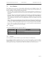
Page 11
SeaShark Detailed Design Document
PHYSICAL DESIGN
3
PHYSICAL DESIGN
3.1
Introduction
SHK-DDD-001 (Issue 2.0)
This section describes how SeaShark is divided into physical design elements and how those
elements communicate with each other.
3.2
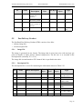
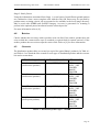
The Process Model
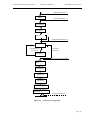
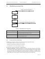
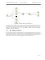
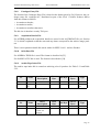
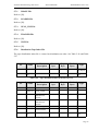
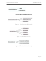
The physical design of SeaShark is shown in the process model of Figure 3-1.
Media
Handler
Hardware
Devices
Interface
Device
Handlers
Process
Steps
Processor
Figure 3-1 Process Model
In Figure 3-1, an ellipse represents a process and a line between two ellipses represents a communication path between two processes.
SeaShark contains the following processes:
• User Interface provides the graphical user interface. It is responsible for the following
processing:
– displaying the windows of the interface to the operator;
– receiving operator input through the windows;
– sending processing request messages to the Processor;
– sending device access messages to the Media Handler;
– receiving asynchronous status messages returned by the Processor;
– receiving asynchronous status messages returned by the Media Handler;
– carrying out some processing tasks without recourse to the Processor;
– controlling the flow of processing through the system.
• Processor carries out the main processing steps. It is responsible for:
– receiving and parsing request messages from the User Interface;
– initiating the appropriate process step, with the correct arguments,
Page 12
SeaShark Detailed Design Document
PHYSICAL DESIGN
SHK-DDD-001 (Issue 2.0)
– monitoring the progress of the processing step by reading log files which the process generates;
– coordinating the sequential execution of several processing steps;
– informing the User Interface of the success or failure of the processing;
– cleaning up after any failed processing.
• Process Steps are executables which each carry out a main processing function. They can be
initiated by the Processor or from the command line. Each executable can selectively use
the parameters passed to it. All Process Steps must write a log file in the standard format.
• Media Handler allows access to a peripheral i/o device. It is responsible for:
– accepting device control requests (mount, unmount etc.) from the User Interface;
– accepting device access requests (reading, write etc) from the User Interface;
– passing requests for sequential or very slow devices (tape) to the appropriate Device
Handlers.
• Device Handlers communicate directly with peripheral devices which do not have their own
file system and therefore cannot be mounted and treated as a normal disk. One Device Handler is spawned for each device on the system. Device Handlers cope with writing multiple
files, thus eliminating the need for excessive communication during a read or write of one
product.
3.3
Inter-Process Communication
Processes communicate with each other in order to send and receive information. In Figure 3-1
different line styles are used to distinguish different means of communication:
• File System Communication is represented by solid directed lines. With File System Communication one process writes information into a disc file and the information is subsequently read by another process. This mechanism is used for communication between the
Process Steps and for communication between the Processor and Process Steps;
• Socket Communication is represented by dotted directed lines. Socket Communication is a
Unix-specific mechanism which allows messages to be sent between different processes,
either on the same computer or on different computers. It is ideally suited for the sending of
small quantities of data;
• System Call Communication isn’t represented in the diagram, but uses the Unix-specific
system function which allows the initiation of a program as a separate executable. The
mechanism is used by the Processor to initiate a Process Step.
3.4
Inter-Process Messages
All inter-process messages are initiated from within SeaShark which creates tokens that are
transmitted to other processes. The receiving process will then return to SeaShark either a copy
of the received token or a TX_ERROR token.
Page 13
SeaShark Detailed Design Document
PHYSICAL DESIGN
SHK-DDD-001 (Issue 2.0)
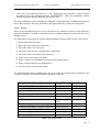
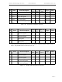
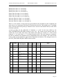
The messages exchanged between SeaShark and other processes are shown in Table 3-1.
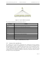
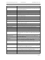
Message Type
Description
Action
Process
TX_MESSAGE
TX_READY
Status request token
Ready token
TX_QUIT
TX_STATUS
TX_DIR_ENTRY
Exit request token
Status request token
Reserved
TX_FORMAT
TX_READ
TX_WRITE
TX_DIST
Format request/acknowledgement token
Read archive product request/acknowledgement token
Write archive product request/acknowledgement token
Write distribution product request/acknowledgement
token
Status request token
Eject request/acknowledgement token
Directory request/acknowledgement token
Exabyte
Exabyte
Exabyte
Exabyte
Exabyte
Exabyte
TX_BACKWARD_FILE
TX_WRITE_EOF
TX_END_OF_MEDIA
Rewind tape request/acknowledgement token
Fast forward tape by one file request/acknowledgement
token
rewind by one file request/acknowledgement token
Write end of file marker request/acknowledgement token
Move to end of tape request/acknowledgement token
TX_MOUNT
TX_UNMOUNT
TX_INITVOL
TX_FIND
TX_RECOVER
TX_MKDIR
TX_CD
TX_CP
TX_DU
TX_DF
TX_CHMOD
TX_CHGRP
TX_CHOWN
TX_TURN_PLATTER
Mount optical disk request/acknowledgement token
UnMount optical disk request/acknowledgement token
Reserved
Reserved
Reserved
Reserved
Reserved
Reserved
Reserved
Reserved
Reserved
Reserved
Reserved
Reserved
TX_BACK
TX_IMPORT
TX_NAVIGATE
Reserved
Import product request/acknowledgement token
Navigate product request/acknowledgement token
TX_COMMAND
TX_EJECT
TX_DIR
TX_REWIND
TX_FORWARD_FILE
Exabyte
Exabyte
Processor
Exabyte
Exabyte
Exabyte
Exabyte
Exabyte
Exabyte
Exabyte
Processor
Processor
Table 3-1 Inter-Process Messages
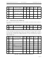
Page 14
SeaShark Detailed Design Document
PHYSICAL DESIGN
Message Type
SHK-DDD-001 (Issue 2.0)
Description
TX_COAST_LINE_ADJUST
TX_LEVEL1
TX_FDP
TX_LEVEL2
TX_LEVEL1DISTRIBUTE
Coastline adjust product request/acknowledgement token
Level1 request/acknowledgement token
FDP request/acknowledgement token
Level2 request/acknowledgement token
Level1 distribution product request/acknowledgement
token
Action
Process
Processor
Processor
Processor
Processor
Processor
Table 3-1 Inter-Process Messages
A standard format is used for the messages and this is shown in Table 3-2.
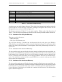
Field Name
_tx_command
_command_arguments
_error_code
_error_status
_return_address
_product_id
_product_file_list
_product_directory
_sensor_info
_device_name
_dest_device_type
_media_id
_sub_order_id
Description
Message type
Command contents
Error code
Error string
Return address
Product id
List of files in product directory
Location of product directory
Sensor type
Device name
Destination device type
Media id
Sub order id
Table 3-2 Inter-Process Message Format
Messages of different type contain arguments which are appropriate for the function.
3.5
Archive Processing Chain
The SeaShark processing is designed as a number of steps which are executed in sequence,
thus forming a processing chain. In this section the different steps in the processing of a raw
HRPT image into a full SeaShark level 1 archive product are detailed. Each step has been
implement as a standalone program which is called in the correct order by the main SeaShark
program. Having each processing stage as separate executable allows any step to be repeated
by the operator simply by running the program on the command line. It also allows ESRIN to
easily replace any step with a newer, improved version.
Page 15
SeaShark Detailed Design Document
PHYSICAL DESIGN
SHK-DDD-001 (Issue 2.0)
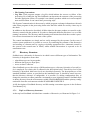
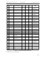
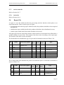
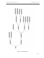
IMPORT PRODUCT
Import
LEVEL0 PRODUCT
Get Orbit Data
Navigate
Extract
NAVIGATED PRODUCT
Coastline
Coastline does
not match
Coastline
matched
Navigate
Ready for Level1 processing
Land Sea
Mask
Extract Calibration Data
Interpolate Navigation Data
Generate
Quicklook
Update Catalogue
Generate
Quicklook
Postscript
LEVEL1 PRODUCT
Figure 3-2 Archive processing chain
Page 16
SeaShark Detailed Design Document
PHYSICAL DESIGN
SHK-DDD-001 (Issue 2.0)
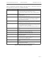
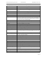
Figure 3-2 describes the execution sequence of the steps. Table 3-1 describes the steps in the
processing chain. See Section 6 for a complete description.
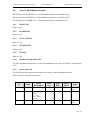
Processing Step
Import
Get Orbit Data
Navigate
Extract coastline
Coastline matching
Renavigate
Land Sea Mask
Extract Calibration data
Interpolate Navigation data
Generate Quicklook
Update Catalogue
Postscript Quicklook
Description
Automatically recognises new passes of AVHRR or SeaWiFS HRPT
data, checks their quality and reformats them to Level 0.
The program Import_AVHRR_Product or Import_SeaWiFS_Product is
used.
Locates the most up-to-date orbit data, in the form of a tbus message, for
use in the navigation.
The program Get_Orbit_Data is used.
Calculates the geographical location, sun angles and satellite angles for a
grid of pixels in an imported image and stores them in a separate file.
The programs Navigate_AVHRR, Navigate_SeaWiFS_GPS and
Navigate_SeaWiFS_TLE are used.
Extracts, from the DCW, the co-ordinates of all coastline segments
within the area covered by the image and stores them in a separate file.
The program Extract_Coastline is used.
Allows the operator to overlay the coastline on a displayed image and to
move the coastline until it best matches the image. The offsets needed to
get a good match are written to a catalogue.
The programs Set_Coastline_Offset and Retransform_Coastline are
used.
Repeats the above NAVIGATE step taking into account the coastline
offsets.
Adds Land Sea Mask data to the image.
The program Create_Land_Sea_Mask is used.
Extracts the calibration information from a Level1 image.
The program Extract_Calibration_Data is used.
Interpolates the navigation data in the given file so that it has a grid line
spacing exactly equal to 1.
The program Interpolate_Navigation_Data is used.
Generates a quicklook image from a navigated Level 1 product.
The program Generate_AVHRR_QuickLook or
Generate_SeaWiFS_Quicklook is used.
The program Update_AVHRR_CatEntry or Update_SeaWiFS_CatEntry
is used.
Converts the quicklook into a printable PostScript version with added
information from the catalogue.
The program Generate_Postscript_QuickLook is used.
Table 3-3 Steps in the Archive processing chain
Page 17
SeaShark Detailed Design Document
3.6
PHYSICAL DESIGN
SHK-DDD-001 (Issue 2.0)
Distribution processing Chain
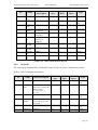
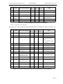
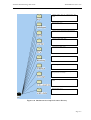
LEVEL1 ARCHIVE PRODUCT
Retrieve
Generate
Distribute
COMPLETED DISTRIBUTION PRODUCT
Delete
Figure 3-3 Distribution processing chain
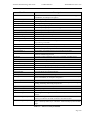
Processing Step
Retrieve
Generate
Distribute
Delete
Description
Located the necessary archive product.
The programs SeaShark and Exabyte are used.
Creates the files needed for a distribution product.
Copies the distribution product files onto archive tape.
The program Exabyte is used.
Deletes the distribution product files from disk.
Table 3-4 Steps in Distribution processing chain
3.6.1
Control of the Processing Chain
SeaShark must maintain visibility and control of the processing chain so that:
• the available products are known to the operator;
• the state of any product is known to the operator;
• it is possible to recover from failed processing.
The necessary control is achieved by a combination of:
• Directory Structures. SeaShark maintains a directory associated with each of the Steps,
into which are placed those data sets that have successfully undergone processing. As data
sets are processed successfully they are moved from one directory to another. When
processing is unsuccessful, SeaShark retains the input data sets and deletes any half-created
output data sets, to ensure that the system remains in the pre-processing state.
Page 18
SeaShark Detailed Design Document
PHYSICAL DESIGN
SHK-DDD-001 (Issue 2.0)
• File Naming Conventions.
• Log Files. Each program outputs a log file which indicate the success or failure of the
processing. By reading the log files SeaShark can determine the outcome of the processing
and take appropriate action, for example it can identify products which are in an incomplete
state and reset them. It can cancel later processing steps.
File System Communication is the means by which programs exchange information with each
other. Most programs in the processing chain write data files which are read by a later step in
the chain.
In addition to the directories described, all files related to the same product are stored in a subdirectory named with the product id. In order to distinguish different files there is a set of file
naming conventions. The directory and file naming conventions described above make it possible to detect inconsistencies in the state of the system.
The control mechanisms are simple and are easily managed by the operator. In the event of
serious system problems it is possible to recover by examining the contents of the directories
and resetting to a known state by copying or deleting appropriate files. Automatic control by
the system is the normal state of affairs, whilst manual intervention is expected to be an
uncommon event.
3.7
Directory Structure
SeaShark uses a hierarchy of directories in which it stores different types of information. The
hierarchy is designed to ensure that:
• related data types are kept together;
• different data types are kept apart;
• access to data is efficient.
Since SeaShark uses a wide variety of different data types, a directory hierarchy of several levels is employed. For clarity, this is reflected in the description below. First the top level of the
hierarchy is described, then lower levels are described separately. The descriptions are of the
standard SeaShark system, as provided on the installation tape. It should be noted, however,
that the directory structure is configurable; it is possible, by editing configuration files, to
change the structure to reflect particular circumstances at an acquisition station. SeaShark finds
its home directory from the environment variable SEASHARKHOME and the primary configuration file from the environment variable SEASHARKCONFIGFILE.
A full description of SeaShark directory and file naming conventions appears in the Software
User Manual [10].
3.7.1
Top Level Directory Structure
At the top level SeaShark is divided into a number of directories, as illustrated in Figure 3-4.
Page 19
SeaShark Detailed Design Document
PHYSICAL DESIGN
SHK-DDD-001 (Issue 2.0)
Figure 3-4 Top Level Directory Structure
The contents of the directories are described in Table 3-5.
Directory
OceanColourF77
PROJ.4
SeaDAS
Xpm
bin
config
data
doc
help
include
install
lib
src
verify
Content
SeaWiFS Level 2 Fortran code
PROJ.4 source code (cartographic projections)
SeaDAS source code (HDF and SeaWiFS calibration)
Xpm code (X window pixmap library)
SeaShark executables
configuration files
data files used by or generated by SeaShark
Documentation
help text files for the GUI, one file per window
header files used in software development
Install files
library files used in software development
source code files used in software development
Data used for verifying import was successful
Table 3-5 SeaShark Directory Content
3.7.2
Structure of the config Directory
The config directory contains all the configuration files, including the X-resources database,
used by SeaShark. A number of configuration files are used to divide the configuration data
into functionally related areas. Under the config directory there is one sub-directory, sensors,
in which configuration data related to a given sensor is stored. There is a generic file, Sensor.cfg, which contains information applicable to all sensors, and a file for each sensor which
contains parameters describing the performance of that sensor, information which is an important input to the processing algorithms.
Page 20
SeaShark Detailed Design Document
3.7.3
PHYSICAL DESIGN
SHK-DDD-001 (Issue 2.0)
Structure of the data Directory
SeaShark generates and uses data sets of many different types, all of which are stored in the
data directory. Because of the varied nature of the data sets, the data directory is divided into a
number of sub-directories, largely based on data type. The top level division of the data directory is shown in Figure 3-5.
Figure 3-5 Structure of the data Directory
The contents of the directories are described in Table 3-6.
Page 21
SeaShark Detailed Design Document
PHYSICAL DESIGN
Directory
catalogue
counters
DCW
orbit_data
orders
products
reports
tapes
tasks
telecom.in
telecom.out
telecom.prepare
SHK-DDD-001 (Issue 2.0)
Content
SeaShark keeps a database, called the catalogue, which holds important details of each generated product. There is an entry in the catalogue for each product. The catalogue entries are
held as separate files which are stored in a hierarchy of sub-directories (see below for more
details).
SeaShark keeps an on going set of counter files for use in numbering orders and reports.
Data for the Digital Chart of the World.
SeaShark keeps a database of orbit data describing the position of the satellite at a given
time. The information is needed for the data processing. Orbit data exists as a number of
files and these which are kept in a number of sub-directories (see below for more details).
SeaShark keeps copies of all ESA product orders and their processing states here.
SeaShark’s main task is to generate products. The generated products are stored under this
directory. A number of sub-directories are used to distinguish products from different sensors and products at different stages of processing.
SeaShark regularly generates a number of reports, detailing the processing activities, for
transmission to the central ESRIN site. The reports are stored here internally.
SeaShark writes a index file for all distribution and archive tapes.
SeaShark monitors the processing of products and their current state. Information relating to
this monitoring function is stored in this directory.
SeaShark exchanges information with several external systems by file transfer over a network. Files to be received from an external system are placed in this directory from where
they can be read by SeaShark.
SeaShark exchanges information with several external systems by file transfer over a network. Files to be sent to an external system are placed in this directory.
SeaShark exchanges information with several external systems by file transfer over a network. Files can be prepared in this directory
Table 3-6 Content of the data Directory top level
3.7.3.1 Structure of the catalogue Directory
The catalogue directory is divided into sub-directories first by sensor, then by year and finally
by month, so that all catalogue entries from a given sensor which relate to the same year and
month are stored together. Each catalogue entry is stored in a separate file.
3.7.3.2 Structure of the products Directory
SeaShark generates products using the data received from two different sensors:
• the SeaWiFS sensor on-board the SeaStar satellite;
• the AVHRR sensor on-board the NOAA series of satellites.
The products from each sensor are kept separate by dividing the products directory into
AVHRR and SeaWiFS sub-directories. For both sensors, SeaShark products are generated by a
processing chain. For each step in the chain, SeaShark maintains a directory into which are
placed all products that have undergone that processing step. As the steps of the chain are executed the product is moved into the appropriate directory. The directories used by SeaShark to
store products as they progress through the processing chain are listed in Table 3-7.
Page 22
SeaShark Detailed Design Document
PHYSICAL DESIGN
Directory
Import
Level0
Navigated
Level1
FDP
L1Dist
Level2
SHK-DDD-001 (Issue 2.0)
Content
Raw HRPT, Level 0 or Level 1 data sets.
Products which have been imported, quality checked and formatted to Level 0.
Products which have been navigated.
Products which have been processed to level 1 archive format.
Products which are in fast delivery format.
Products which are in level 1 distribution format.
products which are in level 2 distribution format.
Table 3-7 Content of the data Directory
A product starts out in the Import directory. When it has been imported and quality checked it
is moved into the Level0 directory. From there it undergoes navigation and is moved into the
Navigated directory and so on. Refer to Figure 3-2.
The directory structure of Table 3-7 is not quite complete. Within each of the directories of
Table 3-7 the files from each product are stored in a sub-directory labelled with the Product Id.
3.7.3.3 Structure of the orbit_data Directory
There are two orbit_data types:
• TBUS messages;
• TLE (Two Line Element) sets.
The orbit_data directory is divided into sub-directories first by orbit_data type (TBUS &
TLE), then by year and finally by month, so that all orbit data messages of a given type which
relate to the same year and month are stored together. Each orbit_data message is stored in a
separate file.
3.7.3.4 Structure of the telecom.in Directory
The telecom directories are used for the electronic transfer of data between an acquisition station and the central ESRIN site. SeaShark exchanges information with several external systems
by file transfer over a network. Files to be received from an external system are placed in the
telecom_in directory from where they can be read by SeaShark. There are two sub-directories:
orders, into which new orders from the central ESRIN site are placed, and tmp, into which
orders can be placed temporarily.
3.7.3.5 Structure of the telecom.out Directory
The telecom directories are used for the electronic transfer of data between an acquisition station and the central ESRIN site. SeaShark exchanges information with several external systems
by file transfer over a network. Files to be sent to an external system are placed in the telecom.out directory. The directory is divided into a number of sub-directories for different data
types as shown in Figure 3-6.
Page 23
SeaShark Detailed Design Document
PHYSICAL DESIGN
SHK-DDD-001 (Issue 2.0)
Figure 3-6 Structure of the telecom.out Directory
The directory “telecom.out” contains a number of directories into which different types of data
are placed ready for transmission to ESRIN. The type of data stored in each directory is self
explanatory. Note that the directories FDP and ORDER are further divided by USER_ID,
ORDER_ID and SUB_ORDER_ID.
3.8
File Naming Conventions
The Software User Manual [10] defines the naming conventions and formats of files used by
SeaShark. Some of the file formats are defined externally to SeaShark whilst some are defined
within the SeaShark project. For the former a reference is made to the relevant documentation;
for the latter a reference is made to the appropriate section of this document.
Page 24
SeaShark Detailed Design Document
3.9
PHYSICAL DESIGN
SHK-DDD-001 (Issue 2.0)
System Start-up
SeaShark is started by executing the User Interface process. The User Interface reads the configuration file to find the location of the processes to start and then spawns each one, as a child
process. The User Interface then attempts to connect to each child by a standard socket. If the
socket is still active a socket reuse facility is tried to initiate the connection. Once each connection has been made the User Interface allows operator interaction.
Spawning a process is done by the Unix-specific fork() and execv() commands. If the processes
cannot be spawned or communications cannot be made, the User Interface cleans up and exits.
A media handler process (one for each different type of device) controls any device access by
queuing requests and allowing the interface to continue without having to process a continual
stream of messages from the device handlers.
The processor process communicates with the interface to get instructions as to the processing
steps required. As each request arrives the processor spawns independent executables to perform the processing. This allows easy maintenance (as each executable can be changed independently of SeaShark) and command line access to the processing steps.
Each process step that the processor spawns runs to completion without giving control back to
the processor. On completion of each process step a log file is written detailing its results.
Every feasible parameter is passed on the command line to these processing steps. No other
means of communication exists between these processes to make development of new processing steps a simple exercise.
3.10
System Close Down
When the User Interface is closed, every open socket connection is sent a message to tell it to
close down. This allows every process to finish its current work and exit in a graceful manner.
3.11
Controlled Termination of Processes
Under certain circumstances an operator may wish to terminate a process before its natural
completion. SeaShark handles this situation carefully to prevent the operator having to restart
SeaShark. It ensures that the integrity of queues and process status flags are kept. System
resources such as file descriptors and any communication resources are relinquished correctly
to avoid problems of free resources later.
Our aim is to separate the processing steps from the main processor process to allow it to be
terminated. However, we do not want to make it difficult to return the status each processing
step.
A solution to this problem is to trap an interrupt which can be generated by the unix system
command ‘kill’. The kill command would be executed with the process id of the processing
step. This would mean that any new processes added to the system would have to trap an interrupt, clean up their system resources, write the log file to indicate what happened and exit.
A second and probably cleaner solution is to kill the child process and monitor the return status
from the processor. Spawn will return an interrupted status and then it is up to the processor
process to clean up after the processing step.
Page 25
SeaShark Detailed Design Document
PHYSICAL DESIGN
SHK-DDD-001 (Issue 2.0)
If we used the first method the child process would exit in the normal way and the system could
handle the termination in the same way as a processing failure. However, the second method is
far simpler to implement and if the processing step is killed by the system an operator the same
recovery procedure would be used. Also the second method allows processing steps more freedom and does not impose restrictions on their implementation.
3.12
Error Handling
As an operational system, SeaShark provides facilities for automatic error checking and recovery. These facilities make it easy, in the event of many system problems, for the operator to
restart the processing. There are, inevitably, some situations in which automatic recovery is not
possible and which therefore need operator intervention to restore system integrity. This will be
done using some unix commands and not via the SeaShark interface. For this reason the underlying structure of the software, for example the directory structure, has been kept simple. The
operator is assumed to be capable of acting on messages issued by the system. This usually
involves checking the directories for incomplete or missing process files, deleting appropriate
ones and renaming others to maintain system integrity and then rerunning the processing from
an appropriate step.
This section describes a number of possible errors and the action needed to recover from them:
• Catastrophic system crash, such as disc failure, unrelated to the SeaShark software. If this
happens then the site system administrator will have to fix the fault and maybe place the
data back on to the system as it was at the last system backup. When access is gained to the
system the SeaShark interface should be run. Any log files or processing files will be
removed and the system returned to a state where all processing can continue. At times the
system may find it has reached a state where there are two products of the same name on the
system. SeaShark will detect this and query the operator to remove the product.
• Killing of processes. If the interface process is killed then each of the sub processes will exit
because each socket will detect the fact that it is not possible to communicate to the interface and the process will finish what it is doing and exit. On restarting SeaShark the system
will read the last status of the system and restart; this may mean that the last few operations
may be lost. If any of the other processes die the system will complain when any requests
are sent to the dead process. It is up to the operator to exit SeaShark and restart it. It will be
possible to continue with remaining processes.
3.13
Tasks
3.13.1
Description
The task is an important concept within the SeaShark design. A task can be defined as an item
of work which SeaShark must perform. A task has an independent identity, separate from the
product or order from which it is derived. Two types of task, a Product Task and an Order Task,
are recognised by the system.
• A Product Task concerns the generation of Level 1 products from Level 0 data. This is routine processing which is carried out on every HRPT data set entering the system. For such
products a task is automatically generated.
• An Order Task concerns the generation of products, such as Fast Delivery products,
requested in user orders. Order Tasks are automatically generated when new orders are
entered into the system, either when they are received in an incoming network directory or
when they are manually entered.
Page 26
SeaShark Detailed Design Document
3.13.2
PHYSICAL DESIGN
SHK-DDD-001 (Issue 2.0)
Storage
A task appears in two places within SeaShark.
• On disc. Disc versions of tasks are held in the Task Store, which is a directory in the data
area. Each task is held in a separate file. The Task Store is split into two sub-directories
called Product and Order. Tasks within the Product directory are labelled with the product
ID. Tasks in the Order directory are within directories labelled with the order ID, containing
tasks labelled with order and sub-order ID’s concatenated. Task files store a major and
minor software version number. This is used to provide compatibility between the software
and task files.
• In memory. Memory versions of tasks are held within the User Interface, which maintains a
list of all current tasks in the system. The list is used in the Task and Batch windows to
allow the operator to view, select and initiate tasks. Every task in memory has a unique
identifier which is generated from within the TaskPool (each task that is loaded into memory is given the next number in sequence). Task identifiers are not stored at any time and are
unique to each execution of SeaShark.
Tasks are only used by the SeaShark main process. Task information required by other processes are passed via tokens.
Object stores are used for task lists and task queues. Both structures are stored each time their
contents changes allowing the system to recreate itself each time it starts up. The object stores
will contain only the list of subject ID’s associated with them.
3.13.3
Task Pool
The TaskPool contains every task that is within SeaShark. Storage is organised by saving each
task in either the product or order task directory. The interface is initialised with the full list of
tasks within the system. When the system is started the Task Pool reads every task within the
task store and loads each into memory. A verify process checks that each task has an associated
product. If it does not, the task is removed. A check is also made that each product has an associated task. A warning message is logged if this is not the case.
The data members of the TaskPool are shown in Table 3-8. New tasks are created when products are imported or retrieved and when new orders are generated. Tasks are deleted when
products and orders are deleted or removed.
Variable
_avhrr_task_list
_seawifs_task_list
_global_task_id
_task_type_filter
_task_status_filter
_scheduling_filter
_process_status_filter
_source_media_filter
Description
Linked list of AVHRR tasks
Linked list of SeaWiFS tasks
Counter for updating task id
Filters used for task list display
Table 3-8 Task Pool data structure
Page 27
SeaShark Detailed Design Document
3.13.4
PHYSICAL DESIGN
SHK-DDD-001 (Issue 2.0)
Individual Tasks
Each task has an instance of a Task class which in turn has an associated TaskForm instance. It
is the TaskForm data that is written to disk.
The data members of the Task class are shown in Table 3-9, and data members of the TaskForm
class are shown in Table 3-10.
Variable
_task_form
_valid
_task_id
Description
TaskForm instance
Boolean to flag valid/invalid tasks
Task id number
Table 3-9 Task data structure
Variable
_dirty_bit
_prepared_telecom
_tmp_suffix
_sensor_info
_schedule_state
_subject_type
_subject_id
_product_id
_state
_process_type
_type_of_product
_optical
_x_offset, _y_offset
_last_x_offset
_last_y_offset
_process_steps
_import_type
_default_optical
Description
TRUE if structure needs to be saved, FALSE otherwise
Indicates that files have been copied to telecom_prepare
Suffix to use for temporary files
Describes the sensor for this task (SensorInfo instance)
The scheduling of the task: none, immediate or batch
Type of task: order, product, reference product, etc.
Either the product or order id.
Either the product or reference product id.
The state of the task, i.e. uninitialised, processing, etc.
Current or next process to happen.
Describes processing type: e.g. L1A, L1B, FDP, etc.
Name of optical order
Offset values used for Coastline Adjust
Offset values used for the previous Coastline Adjust
Work that has been done on the task.
Type of import: HRPT, Level0, Archive or Level1
Default string for _optical
Table 3-10 Task Form data structure
The TaskForm data members _process_steps and _process_type are used to control task
processing. For an inactive task _process_type specifies the next step in the processing
sequence. The mask _process_steps records each step of the processing sequence that the task
has undergone or that has been selected for future processing. This parameter reflects the disposition of toggle buttons on the task form window.
The function update_task() is used to update the Task Pool when a task changes. The disk copy
of the task is also updated if _dirty_bit is set.
Processing is initiated by placing the task on one of the task queues.
Page 28
SeaShark Detailed Design Document
3.13.5
PHYSICAL DESIGN
SHK-DDD-001 (Issue 2.0)
Task queues
There are two types of task queue used in SeaShark.
• Immediate. The next queued task will become active as soon as the current active task on
this queue completes.
• Batch. When batch processing is activated the tasks on this queue are transferred to the
associated immediate queue for processing. This type of queue acts as a holding store; tasks
are not processed directly from it.
There are four queues of each type.
• Archive. This queue handles tasks for archiving, post-archiving deletion and retention as
reference products.
• Distribute. This queue handles tasks for distribution and post-distribution deletion.
• Retrieve. This queue handles retrieval tasks.
• Process. This queue handles all other processing.
The data members of the TaskPool are shown in Table 3-8.
Tasks are placed on the relevant queue either by operator action or automatic detection of
import products or orders. The task state is set to Waiting (Queued). On every SeaShark timer
event the four immediate queues are polled. If the queue is not active, the first waiting task is
serviced. When a sequence of processing steps is in progress the task is moved as necessary
from one queue to another. In practice this only involves tasks in the processor queue which
may be moved either to the archive queue or to the distribute queue.
Variable
_task_queue
_queue_store
_loaded_ok
_tmp_suffix
_seawifs_entries
_avhrr_entries
Description
Linked list of tasks in the queue
File for storage of task queue store. This name is supplied by a configuration parameter (eg “process_immediate_queue”).
Boolean indicating the load status of the task queue store file.
File name extension for temporary queue store file (default .tmp).
Number of SeaWiFS tasks in the queue.
Number of AVHRR tasks in the queue
Table 3-11 Task Queue Store data structure
3.13.6
Task creation
The following steps show how a new task may be created:
1) Create a new Task instance.
2) Set the task data members to the relevant values using the appropriate member
functions. Typically these will include SetScheduleState(), SetSubjectID(),
SetProcessType(), SetProcessSteps(), SetSensorType() and SetTaskState().
3) Save the current global task ID ( globals->task_pool().global_task_id() ).
4) Use globals->task_pool().next_task() to create the new task. This will be assigned
the current global task ID.
Page 29
SeaShark Detailed Design Document
PHYSICAL DESIGN
SHK-DDD-001 (Issue 2.0)
5) Check that the task did not already exist by comparing the task ID with the ID
saved in 3) above.6) Use update_task() to save a copy of the task to disk.
Some of the member function that are used to handle tasks are shown in Table 3-12.
Function
GetScheduleState
GetTaskState
GetProcessType
GetTypeOfProduct
GetTypeOfProductString
GetProcessSteps
GetName
getProductDirectory
getCurrentProductDirectory
next_task
update_task
get_task
remove_task
product_on_disk
Description
Indicates whether the task is on an immediate queue, batch queue or none.
This is one of: Uninitialised, Waiting, Processing, Archiving, Retrieving, Distributing or Error.
This indicates the next or current process.The type for Level2 processing is
‘TypeLevel2’, and the specific processing is indicated by GetTypeOfProduct.
This is one of: L1Arc, L1ADist, L1BDist, L2ADist, L2BDist, FDPDist,
L2CDist. There are also Boolean functions available for individual product
types; eg IsL1A, IsFDP.
There are a number of functions available that return task parameters as text
strings. These are mainly used for display purposes.
This is closely linked to GetTypeOfProduct. The process_steps mask consists
of all the process_type values for a task OR’d together.
This returns a string containing the product, or order, ID.
This returns where the product data required for processing the next step is
stored on the system.
This returns where the product files are currently stored on the system, or an
error if the product files have not yet been created.
Create a new task with the next global task id.
Update a task in memory and on disk.
Searches for a task within the task pool and returns it if found.
Searches for a task within the task pool and removes it if found.
This routine searches for products used by the task. Return values indicate
whether the product is on disk, and if the product is referenced by an order.
Table 3-12 Selected task member functions
3.13.7
Task example
Consider a task which is to undergo Navigation processing. When the task has been selected
from the task list, the task form window is built using AppearTaskForm(). The toggle buttons
are set using the _process_steps and _process_type values. In this example no toggle buttons
are shown as being depressed.
Now press the Navigation button in the task form window. The function ProcessStepChanged()
checks that the button configuration is valid before setting the button display and tests the
_process_type bit in the _process_steps mask to confirm that the next process to run matches
the button selection. A confirm window is then displayed to allow processing to begin. When
Immediate is pressed the task’s schedule state is set to Immediate, and the task state to Waiting
(i.e. Queued). Using update_task(), the task is updated in memory and on disk. Finally the task
is placed on the process immediate queue.
On the next SeaShark timer event the queue handler function service() will poll the process
immediate queue. If the navigation task is the next task that is in the Waiting state, it will be
processed by do_service(). This function builds a token and passes it to processor_handler(). It
also sets the task state to Processing and updates the task in memory and on disk.
Page 30
SeaShark Detailed Design Document
PHYSICAL DESIGN
SHK-DDD-001 (Issue 2.0)
In processor_handler(), SendToken() sends the token to the processor process; tasks are only
used in the main SeaShark process.
When processor has completed navigation, a token is sent to the processor_handler() function,
RecievedToken(). Using the product ID contained in the token, the relevant task is fetched
using get_task(). If the navigation completed successfully, the task state is set to Uninitialised
and _process_type is set to the next processing step. The next step depends on which task form
toggle buttons have been pressed. If no further processing was selected, _process_type will be
set to TypeCoastLineAdjust, the schedule state set to None, and the task removed from the
process immediate queue. Finally the task is updated in memory and on disk.
3.14
Orders
3.14.1
Terminology
The following terminology is used:
• An ESA Order File is a file containing ESA Orders.
• An ESA Order or Order is a request for product generation. It is represented by a single line
in the ESA Order File which defines the product to be generated in terms of reference product ID and either centre latitude/longitude or start and stop times. See [36] for more details.
3.14.2
External Interfaces
Order handling at an acquisition station uses two external interfaces:
• the import of ESA Order Files from ESRIN;
• the return of Order Status Files to ESRIN.
These interfaces are specified by the formats of the ESA Order and Order Status files, and the
directory structure used for file exchange. The formats of the files are defined in [36] (standing
orders are not supported), with clarification of the order status codes provided in email messages from ESRIN. The file names and directory structures are defined below.
3.14.3
Physical Design
SeaShark uses three directories to store orders:
• an import directory, $SEASHARKHOME/data/telecom.in/orders, into which new ESA
Order Files from ESRIN are placed. This is done by an external telecommunications system
and is outside the scope of SeaShark. No assumptions are made about the names of files in
the import directory;
• a store directory, $SEASHARKHOME/data/orders/Store, into which orders are placed
ready for processing. The store directory is sub-divided into directories uniquely labelled
using the order code and sub-order number taken from the Order. Each subdirectory contains two files: a copy of the ESA Order File (named “Order”) and an Order Status File
(named “OrderStatus”).
• export directories, $SEASHARKHOME/data/telecom.out/orders, into which Order Status
Files are placed for transmission to ESRIN, and $SEASHARKHOME/data/telecom.out/
fdp, into which FDP products are placed. The transmission is the responsibility of an external telecommunications system and is outside the scope of SeaShark. The fdp directory is
subdivided into directories labelled using the following fields from the Order: destinationPage 31
SeaShark Detailed Design Document
PHYSICAL DESIGN
SHK-DDD-001 (Issue 2.0)
code/order-code/suborder-number (see [36]). Within the order directory, each of the files
are named using the following pattern: AASSSSSS.EEE, where AA=acquisition station,
SSSSSS=sequence number and EEE=extension (“sta”).
The above pathnames can be changed by editing the configuration file. SeaShark automatically
moves files from one directory to another at the appropriate time in the processing chain.
3.14.4
Errors
There are several different types of error: non-fatal errors which are reported via the shell window that SeaShark is running in, and fatal errors or warnings which are reported by the use of
dialogue boxes.
The following list describes the actions which SeaShark can take when an order error occurs:
1) Reject and delete the order.
2) Reject the order and write a status file.
3) Place the order in an error state.
4) Ignore the error and use a default where appropriate.
5) Move the order to the failed order directory.
6) Write an error message to the shell.
7) Write a simple error notification message in the Main window.
8) Show an info/warning/error dialogue box.
9) Crop the image to fit the pass height.
The following table shows possible errors, the point in the processing chain at which the error
is detected, and the action that SeaShark will take in each case.
Error Description
Invalid/missing ESA Order code
Invalid/missing Sub-order Number
Invalid/missing Satellite Id
Invalid/missing Satellite Mission Number
Invalid/missing Sensor Id
Invalid/missing/unknown Product Code
Invalid/missing Centre Latitude/Longitude
Invalid/missing Bottom Latitude/Longitude
Invalid/missing Start/Stop Date
Invalid/missing Start/Stop Time
Invalid/missing Pass Id
Stage Detected
Import
Import
Never detected
Never detected
Never detected
Processing (FDP
only)
Processing
Never detected
Never detected
Processing
Import
Action
5,6,7
5,6,7
4
4
4
3,6,8
3,6,8
4
4
3,6,8
2,6,7
Table 3-13 Order errors
Page 32
SeaShark Detailed Design Document
PHYSICAL DESIGN
Error Description
Stage Detected
Unknown Pass Id
Invalid/missing Order Type
Invalid/missing Media Type
Invalid/missing Product Type
Invalid/missing Priority
Invalid/missing Product Station
Invalid/missing Destination Code
Processing
Import
Distribution
Import
Never detected
Never detected
Distribution (FDP
only)
Never detected
Never detected
Processing
Import
Processing
Import
Invalid/missing Shipping code
Invalid/missing Comments (external order)
Invalid/missing Comments (internal order)
Order already imported
Order-by-location size > pass height
Directory created in telecom.in/orders
SHK-DDD-001 (Issue 2.0)
Action
3,6,8
2,6,7
4,6
2,6,7
4
4
3,6,8
4
4
3,6,8
5,6,7
6,9
4
Table 3-13 Order errors
3.14.5
Failed Order Directory
If an order is received which has a missing or corrupt order code and/or sub-order number, it
cannot be identified, so no directory can be created for it on the system. Also, because the order
cannot be identified, a status file cannot be written.
To prevent the order being deleted and lost completely, it is copied to a directory at the location
specified by the failed_order_directory tag in the SeaShark.cfg file. Rejected orders, for which
no status file may be written, are copied to this directory and named using an incrementing
counter e.g. FAIL000001. A message is written to the shell when this happens, so that the error
and its associated FAIL file can be matched. In the case of multi-order files, only the rejected
sub-order is copied, not the whole multi-order file. If no location is specified in the SeaShark.cfg file or the specified directory does not exist, the failed order directory is not used and
rejected orders are deleted (action 1, above).
It is the operator’s responsibility to empty this directory when necessary. The directory is not
polled.
3.14.6
Multi-Order Files
A multi-order file is an ESA Order File which contains more than one ESA Order. Each order
in a multi-order file is processed individually. This prevents the whole multi-order file from
being rejected whenever an error is detected in a single order.
3.15
Archive Products
3.15.1
Physical Design
Refer to Table 3-7, “Content of the data Directory,” on page 23 and See “Import” on page 72.
Page 33
SeaShark Detailed Design Document
3.15.2
PHYSICAL DESIGN
SHK-DDD-001 (Issue 2.0)
Errors
The following table contain a list of some of the errors that can be generated on attempting to
produce an archive product. Processing errors are also discussed in the Software User
Manual [10].
Stage of
processing
any stage
Error text
Invalid sensor <sensor code>
any stage prior Error cannot open the input catato archiving
logue entry file
archiving
Disk full tape index not written for
<product id>
importing
Failed to read import directory
any stage
navigation
any stage
navigation
import
import
import
navigation
navigation
any stage
navigation
Level 1
Description or error
The sensor used in the product is not
listed in station.cfg
The catalogue.iuf has been deleted or
made read only.
The disk is full.
The import directory does not exist or
is read only.
Unable to write Q-store file
The list of queues is unavailable
No valid GPS found: please use TLE The GPS does not exist.
navigation
Executable does not exist <executa- The executable mentioned does not
ble name>
exist in the $SEASHARKHOME/bin
directory
Product is in an invalid state.
Import failed
Image read failed
the IMAGE_HRPT file does not exist
or is read only.
Image file is invalid
The IMAGE_HRPT file is incorrectly formatted
Not enough memory
The disk is full
Note enough memory to access the Memory problems
DCW database
cannot access the DCW directory
The DCW directory defined in the
SeaShark.cfg parameter
dcw_database_directory does not
exist.
Tasks are incompatible for multiple The multiply selected tasks are not at
selection
the same stage of processing
cannot create land sea mask file
The product directory had been
deleted or is read only
cannot create such a large quicklook The size of the quicklook is too large.
Table 3-14 Processing Errors
Page 34
SeaShark Detailed Design Document
Stage of
processing
Level 1
Level 1
PHYSICAL DESIGN
Error text
SHK-DDD-001 (Issue 2.0)
Description or error
Error in given sampling factor
The sampling factor given in the SeaShark.cfg in the parameter
quicklook_<sensor>_sampling_factor is incorrect.
Sampling factor must be greater than The sampling factor given in the Seazero
Shark.cfg in the parameter
quicklook_<sensor>_sampling_factor is incorrect.
Table 3-14 Processing Errors
Page 35
SeaShark Detailed Design Document
4
PROCESSING INTERFACE
SHK-DDD-001 (Issue 2.0)
PROCESSING INTERFACE
This section defines how SeaShark executes processing tasks. Some are automatic, others
require operator intervention.
4.1
Archive Processing
4.1.1
Polling The Import Directories
SeaShark makes use of timers to trigger events. On every timer expiry (default 10 seconds) the
$SEASHARKHOME/data/products/sensor/Import/* directories (Archive, HRPT, Level0 and
Level1) are checked for new directories.
If a directory exists in the HRPT directory, this new directory is searched to see if it contains an
AQTIM.DAT file. If an AQTIM.DAT file exists and an IMAGE_HRPT file is also present, both
files are imported into SeaShark and a Task is created which appears in the Task List window.
If a directory exists in one of the other Import subdirectories, this new directory is searched to
see if it contains a catalogue.iuf file. If a catalogue.iuf file exists, various files are imported into
SeaShark and a Task is created. The imported files are those required for a product processed
to the level specified by the import directory name e.g. a level1 product imported via the
Level0 import directory will be imported as a level0 (pre-navigated) product, and the Task created will reflect this.
4.1.2
Viewing The Status Of Products
The Task List window allows the operator to see the details of a product, to initiate its processing and monitor its progress. It allows the processing of lists of products which are at the same
stage of processing (Batch processing). Each line of the list represents a product and shows the
current status of that product’s processing. The information shown is:
Product ID – The identifier for the product.
Level – The current processing stage for the product. The following values are used:
• Import (used while the product is being imported)
• L0 (used prior to navigation)
• L1 Arch (used after navigation)
Status – The processing activity flag for the product. The following values are used:
• - (used for archived products where no further processing is possible)
• Ready (the product is ready for further processing)
• Queued (the product has been added to the Immediate queue for processing)
• Error (something went wrong with the last processing step)
• Active (the product is undergoing processing)
• Batch (the product has been added to the Batch queue, and is awaiting the start of the
next batch job)
To – The next stage of processing for the product. The following values are used:
• Import
• Navigate
• Coast line adj
Page 36
SeaShark Detailed Design Document
PROCESSING INTERFACE
SHK-DDD-001 (Issue 2.0)
• Level 1
• Delete
• - (used for archived product)
4.1.3
Counting The Products On The System
The Main window contains a count of the number of products on the system.
4.1.4
Selecting Processing Steps
A product can be progressed through the five processing steps by operator intervention. The
required steps can be selected using the Processing Steps toggle buttons in the Task List window. Selecting the Process button will cause a Confirm window to appear and the selected
processing steps will commence when a queue is selected.
4.1.5
Viewing The Image
A non-active product can be displayed at any stage using the Display button in the Task List
window to bring up the Display window. The desired image band can be selected from the
band menu and the band displayed by selecting the Display button in the Display window.
4.2
Order Processing
4.2.1
Polling The Import Directory
As mentioned earlier, SeaShark makes use of timers to trigger events. On every timer expiry
(default 10 seconds) the $SEASHARKHOME/data/telecom.in/orders directory is read. When a
new ESA Order File appears in the Import directory it is checked for various errors (see Table
3-13). If no problems occur, the order is copied to the $SEASHARKHOME/data/orders/Store
directory and a Task appears in the Task List Window.
4.2.2
Processing
As processing of the ESA Order proceeds, the OrderStatus File is modified to reflect the
processing which has taken place. When processing is complete, and the products have been
written onto a distribution media or into a telecom directory, a Shipping Date and appropriate
code are added to the Order Status File (See [36] for specific field details).
4.2.3
Sending Status Files
A regular check is made for orders with a complete shipping date (the time between each check
is set in the Prepare Order Status timer). Such orders are moved to the export directory and
renamed with the file name SSNNNNNN.sta (where SS is the Station code and NNNNNN is a
unique counter).
4.2.4
Purging The Order Store
After completion, ESA Orders are kept on the system for a predetermined ‘retention period’
(the time is set in the Clear Order timer). A thirty day check is made to examine their Shipping
Dates and copy those ESA Orders whose retention period has expired to a backup directory. It
is the responsibility of the operator to manually remove them from the backup directory, if necPage 37
SeaShark Detailed Design Document
PROCESSING INTERFACE
SHK-DDD-001 (Issue 2.0)
essary.
4.2.5
The Operator Interface
The operator interface provides the means for controlling the processing of orders. All control
takes place using the Task List window, as for archive product processing. Selecting an order
will show the processing steps completed, and those still to be performed, in the Processing
Steps section of the Task List window. From here, the operator can select which steps are to be
performed and execute the processing by selecting the Process button. A Confirm window will
appear and processing will commence when a queue is selected.
4.2.6
Counting The Orders On The System
The Main window shows the number of Orders which are on the system, either waiting to be
processed or undergoing processing. Those orders which have been processed and are still on
the system, pending expiry of their retention period, are not included in the total.
4.2.7
Viewing The Status Of Orders
The Task List window allows the operator to see the details of an Order, to initiate its processing and to monitor its progress. It also allows the processing of lists of orders.
The filters at the top of the window allow the operator to view orders which satisfy the selected
criteria (the display is updated automatically). Each line in the list represents an order and
shows the current status of the order’s processing. The information shown is:
• Product – the identifier for the reference product associated with the order.
• Order – the unique identifier for the order (ESA order code and suborder number combination.
• Level – the stage to which the order has been processed. The possible levels are:
• - (used before retrieval and after distribution)
• L1 Arch (used by retrieved orders)
• Order type (e.g. L1B,L2A,L2B,LFD1,SFD1) (used by generated product)
• Status – the current processing state for the order. The possible states are:
• Error – something went wrong with the last step.
• Ready – the order is ready for the next processing stage.
• Batch – the order is ready for the next batch job.
• Queued – the order will undergo processing when the immediate queue empties.
• Active – the order is undergoing processing.
• To – defines the next stage in the processing chain. The possible stages are:
• Retrieve – ensure the reference product is on the system.
• Order type Processing – generate the ordered product.
• Order type Distribute – write the generated products to the distribution medium.
• Delete – remove the generated products from the system.
• Customer – the identifier for the customer for the order.
• Media – the distribution media type identifier.
4.2.8
Initiating Order Processing
When an Order first enters the system it is in the retrieve state, in which it can be selected and
Page 38
SeaShark Detailed Design Document
PROCESSING INTERFACE
SHK-DDD-001 (Issue 2.0)
initiated. Retrieval starts the processing chain. The required steps in the chain are determined
by SeaShark and the appropriate steps are checked in the Task List window. Once the Order
has been initiated it proceeds automatically. The operator would not normally intervene in the
processing, unless:
• operator intervention is needed to place an archive or distribution medium in the tape drive.
The system uses a pop-up dialogue to prompt the operator when medium handling, for
example the insertion of a tape, needs to be done;
• the operator wishes to cancel the Order. This is done from the Task List window, in which
case the Order reverts to the uninitialised state and can subsequently be reinitialised.
4.2.9
Viewing Full Order Details
In the Task List window the most important details from the Order are shown. Full details can
be seen by selecting the Order Form button in the Task List window which will cause the Order
Form window to be displayed. This shows information as it is appears in the Order itself,
including the fields which are not needed by SeaShark.
4.2.10
Entering New Orders
4.2.10.1 External Orders
For external orders the order file is placed directly into the $SEASHARKDATA/telecom.in/
orders directory.
4.2.10.2 Order Form Window
In the discussion so far, orders have arrived via network and have been automatically imported
into the system. In some circumstances, for example when network communication with
ESRIN is not possible, it may be necessary to manually enter orders into the system. This can
be done using the same order form which was described above for viewing full order details.
From the order form, an order file is created and copied into the $SEASHARKDATA/telecom.in/orders directory. This order file is then detected and used in the same way as for external orders.
An order contains a description of the product which is required and the distribution medium
needed to disseminate it. Therefore, when an order arrives the process options can be set automatically within the Task List window, and the task needs no intervention apart from the initial
decision between immediate or batch processing.
When an order is initiated, its requirements are first determined and tasks created for retrieval
of the desired products from the archive. Each request becomes a new task and is placed within
the TaskPool. The calling task will interrupt itself and wait for each of the tasks to be completed. In batch mode each of the tasks are placed on the batch queue. (It is assumed that in
immediate mode the operator will be at his/her terminal controlling the process.)
When an order is distributed to tape, the tape capacity is checked. If the quota for the device
(defined within the configuration file) is reached, the task is placed in an error state.
4.2.10.3 Interactive Orders
An interactive order is created using the Interactive Control window, which is displayed by
Page 39
SeaShark Detailed Design Document
PROCESSING INTERFACE
SHK-DDD-001 (Issue 2.0)
selecting an archive product from the Task List window and selecting the Process button. The
Display window will also appear, if the archive product is not from an optical disk, so that the
desired part of the archive product can be selected (optical products are already formatted by
ESRIN and fixed at 1440 lines in length). When the image is displayed, the start and stop lines
are overlaid in red and can be moved by the operator using the arrow keys in the Interactive
Control window. The times shown to the left of the text boxes will be written into the order
when it is generated, and the line numbering starts at zero and is inclusive i.e. if the start line
shows “1” and the stop line shows “498”, the final product will contain 498 lines. When the
operator is happy with the settings in the Interactive Control window, an appropriate order will
be generated when a selection from the Accept menu is made. This order file is placed in the
$SEASHARKHOME/data/telecom.in/orders directory and processed in the same way as any
other order.
4.3
Immediate and Batch Processing
SeaShark offers two types of processing, Immediate Processing and Batch Processing. Immediate Processing refers to work items which the operator wants the system to execute at the earliest opportunity. Batch processing refers to work items which the operator wishes to make
ready for execution but whose execution he wishes to defer until a later time.
All Processing is carried out by the Processor which sequentially reads items of work from a
Process Queue. There is only one Processor and only one Process Queue. All work items,
whether immediate or batch, are entered into the Process Queue. However, immediate work
items are entered at the top of the queue and are therefore selected for processing first. If the
Process Queue contains only batch items, processing only continues if the operator has turned
on the batch processing option. This allows the operator to prepare work items which are
queued for batch processing, which can be turned on at a suitable time, typically just before he
goes home in the evening.
Since there is only one Processor, which processes one work item from the Process Queue at a
time, SeaShark has no concept of concurrent processing, whereby several work items are being
processed at the same time. Because of the nature of SeaShark processing, there is no significant advantage to be gained by having more than one work item being processed simultaneously by the system. This means that even ‘immediate’ work items might have to wait a short
time before they are processed.
The Process and Batch queues are internally maintained lists of queued Tasks and are initialised from the Task Pool when SeaShark starts up. As queuing information forms part of a Task
object, there is no danger of the queue states being lost, in the event of a system crash for
example, as all Task files are written to disk.
If the operator selects several Tasks to add to a queue (a multiple selection), Tasks will be
added as if they had been selected individually and in the order they appear in the Task List
window. To change the order in which Tasks are processed, they must be added to a queue individually in the required order of processing.
Page 40
SeaShark Detailed Design Document
5
FILE FORMATS
SHK-DDD-001 (Issue 2.0)
FILE FORMATS
This section defines the file formats used within the SeaShark project.
5.1
AVHRR HRPT Product
The processing of an AVHRR HRPT pass requires the presence of two files after the acquisition:
• the AVHRR HRPT Level 0 file coming from the satellite,
• the “AQTIM.DAT” file generated by the acquisition software.
5.1.1
AVHRR HRPT Level 0 File Formats
The AVHRR HRPT Level 0 format has a number of variants. The general form of the format is
defined in “Data Extraction and Calibration of TIROS-N/NOAA Radiometers”, Rev. 1, Technical Memorandum NESS-107, dated October 1988 from NOAA [39]. The variants are
described below.
The AVHRR HRPT Level 0 file written by the acquisition software can be in one of three different formats that are acceptable to SeaShark:
• the “DLR” type format, composed of a 2 Byte header, followed by a 16-bit HRPT data
block containing a sync in 22180 Bytes followed by a Calibration data block in 346 Bytes:
total length = 22548 Bytes;
2 Bytes
H
22180 Bytes
Sync
346 Bytes
HRPT 16 Bits
Calibration Block
22528 Bytes
• the “Dundee” type format, identical to the “DLR” type, but the total record length is
blocked to a multiple of 8K (memory page size): total length= 24576 Bytes;
H Sync
HRPT 16 Bits
Calibration Block
Pad
24576 Bytes
• a basic format without header or calibration data, composed of a 12 Bytes sync plus the 16bit HRPT data in 22180 Bytes: total length= 22192 Bytes.
HRPT 16 Bits
Sync
22192 Bytes
Page 41
SeaShark Detailed Design Document
5.1.2
FILE FORMATS
SHK-DDD-001 (Issue 2.0)
AQTIM.DAT File Format
This file is generated during the acquisition and is used to determinate the date of the pass
(which is not present anywhere in the HRPT) and the first and last valid time lines. The
AQTIM.DAT file is a text file. The format of the file is described in Table 5-1.
No
1
Name
Stop
byte
Size in
bytes
2
acq_start_date
Satellite Number for
NOAA
new-line char
Acquisition start date
3
acq_start_time
new-line char
Acquisition start time
11
12
11
20
1
9
4
acq_stop_date
new-line char
Acquisition stop date
21
22
21
27
1
6
5
acq_stop_time
new-line char
Acquisition stop time
28
29
28
37
1
9
new-line char
Number of scan lines
within the passage
new-line char
38
39
38
42
1
4
43
43
1
6
sat_no
Start
byte
Short Description
no_scan_lines
Table 5-1
1
3
3
4
5
4
10
1
6
Format
ASCII :
∇nn
ASCII :
YYMMDD
ASCII :
HHMMSSmmm
ASCII :
YYMMDD
ASCII :
HHMMSSmmm
ASCII :
nnnn
AQTIM.DAT Format
Note: The start and stop dates and times refer to the times of the first and last lines in the HRPT file.
Example:
∇11
930828
074558987
930828
075341320
2775
where ‘∇’ represents a space character.
5.2
SeaWiFS HRPT Product
The processing of a SeaWiFS HRPT pass requires only the SeaWiFS HRPT Level 0 file.
There is no currently defined SeaWiFS equivalent of the AVHRR AQTIM.DAT file (an empty
file is used to trigger import [11]).
Page 42
SeaShark Detailed Design Document
5.3
FILE FORMATS
SHK-DDD-001 (Issue 2.0)
SeaWiFS HRPT Level 0 File Formats
There are three formats of the SeaWiFS HRPT Level 0 file accepted by SeaShark. The first is
the raw HRPT data as acquired from the satellite [38]. SeaShark also accepts HRPT data as reformatted by acquisition software into either NASA Frame Formatter Level 0 [40] or HMF
SeaWiFS HRPT format [45].
The HMF SeaWiFS HRPT data format, in use for example at Scanzano ground station, contains a series of Image Data Records (one per minor frame) each of which is formatted A
described in Table 5-4.
It is important to note that in the HMF Image Data Record the raw 10-bit HRPT data words are
unpacked to 16-bit short words (I*2) and that all short words are byte-swapped :
i.e. a 10-bit word ‘abcdefghij’, where ‘a’ is the most significant bit and ‘j’ is the least significant bit, is stored in a 16-bit short word as ‘cdefghij000000ab’. Further, it should also
be noted that whilst the State-of-Health field within the raw HRPT data consists of a series of
8-bit words, this data is unpacked as if it were a series of 10-bit words. This packing of the data
fields is dealt with accordingly by SeaShark during the import process.
No
Name
1
Frame_Sync
2
Spacecraft_ID
3
Time_Tag
4
SOH_TLM
5
Inst_Anc_TL
M
6
Gain_TDI
7
Start_Sync
8
Dark_Restore
9
Image_Data
10
Stop_Sync
11
Pad
12
Aux_Sync
Short Description
Start
byte
Stop
byte
Size in
bytes
HRPT Frame Sync (6 × 16-bit
words)
Spacecraft Identifier (2 × 16bit words)
Spacecraft time tag (4 × 16-bit
words)
Spacecraft state of health
telemetry (775 × 8-bit words
unpacked into 620 × 16-bit
words as if from 10-bit data)
SeaWiFS instrument and
ancillary telemetry (44 × 16bit words)
Gain and TDI for the 8 bands
(8 × 16-bit words)
Start sync for the SeaWiFS
imagery (8 × 16-bit words)
Dark restore pixels for the 8
bands (8 × 16-bit words)
Pixel interleaved SeaWiFS
image data for the 8 bands,
1285 pixels per scan line
(1285 × 8 × 16-bit words)
Stop sync for the SeaWiFS
imagery (8 × 16-bit words)
Pad (2 × 16-bit words)
1
12
12
13
16
4
17
24
8
25
1264
1240
1265
1352
1353
HRPT auxiliary sync (100 ×
16-bit words)
Table 5-2
Type
Times
unsigned
short
unsigned
short
unsigned
short
unsigned
short
6
88
unsigned
short
44
1368
16
8
1369
1384
16
1385
1400
16
1401
21960
20560
unsigned
short
unsigned
short
unsigned
short
unsigned
short
21961
21976
16
8
21977
21980
4
21981
22180
200
unsigned
short
unsigned
short
unsigned
short
2
4
775
8
8
10280
2
100
Format of the HMF SeaWiFS HRPT Image Data Record
Page 43
SeaShark Detailed Design Document
5.4
FILE FORMATS
SHK-DDD-001 (Issue 2.0)
SeaWiFS and AVHRR Level 1 Archive Product
A Level 1 Archive Product contains the files listed in Table 5-3. The formats of most of these
files are the same for SeaWiFS and AVHRR products; where there are differences, these are
explained in the text.
File Type
Format
imagery file
navigation data file
land/sea mask file
coastline file (a)
calibration data file (b)
quicklook file
postscript quicklook file
catalogue entry file
acquisition details file (c)
orbit data file
Table 5-3
see Section 5.4.1
see Section 5.4.2
see Section 5.4.3
see Section 5.4.4
see Section 5.4.5
see Section 5.4.6
see Section 5.4.7
see Section 5.4.8
see Section 5.4.9
see Section 5.4.10
Files in a Level 1 Archive Product
(a) temporary file: exists only on disk when the product is first generated.
(b) AVHRR only.
(c) temporary file: exists only on disk when the product is first generated (SeaWiFS only).
5.4.1
Imagery File
The SeaWiFS imagery file contains a number of Image Data records, each of which is formatted as described in Table 5-4.
No
1
2
3
4
5
6
Name
Short Description
Scan_Line_F
lag1
Scan_Line_
Day
Scan_Line_T
ime
blanks
Spacecraft_I
D
Spacecraft_T
ime_Tag
Start
byte
Stop
byte
Size in
bytes
Scan line flag
1
2
2
Scan line day (Day of Year)
3
4
2
Scan line time (millisecs of day)
5
8
4
9
10
9
13
1
4
14
21
8
Spacecraft Identifier (2 × 16-bit
words)
Spacecraft time tag (4 × 16-bit
words)
Table 5-4
Type
unsigned
short
unsigned
short
unsigned
short
ASCII
unsigned
short
unsigned
short
Times
1
1
2
1
2
4
Format of the SeaWiFS Level 1 Image Data Record
Page 44
SeaShark Detailed Design Document
No
7
8
Name
Short Description
Spacecraft_S
OH
Intstrument_
Telemetry
9
Gain_TDI
10
Start_Synch_
Pixel
Dark_Restor
e_Pixel
Image_Data
11
12
13
Start
byte
Stop
byte
Size in
bytes
Type
Times
796
775
byte
775
884
88
unsigned
short
44
900
16
8
Start synch pixel for the 8 bands
916
16
932
16
21492
20560
21508
16
unsigned
short
unsigned
short
unsigned
short
Structure:
Table 5-5
unsigned
short
901
Dark restore pixels for the 8
917
bands
Pixel interleaved SeaWiFS data
933
(1285 pixels per scan line)
Stop_Synch_ Stop synch pixels for the 8 bands 21493
Pixel
Name
SHK-DDD-001 (Issue 2.0)
Spacecraft state of health teleme- 22
try (775 × 8-bit words)
SeaWiFS instrument and ancil797
lary telemetry (44 × 16-bit
words)
Gain and TDI for the 8 bands
885
Table 5-4
No
FILE FORMATS
8
8
1285
8
Format of the SeaWiFS Level 1 Image Data Record
Short Description
Start
byte
Stop
byte
Size in
bytes
1
Band_1
Band 1 of the SeaWiFS sensor
N/A
N/A
2
2
Band_2
Band 2 of the SeaWiFS sensor
N/A
N/A
2
3
Band_3
Band 3 of the SeaWiFS sensor
N/A
N/A
2
4
Band_4
Band 4 of the SeaWiFS sensor
N/A
N/A
2
5
Band_5
Band 5 of the SeaWiFS sensor
N/A
N/A
2
6
Band_6
Band 6 of the SeaWiFS sensor
N/A
N/A
2
7
Band_7
Band 7 of the SeaWiFS sensor
N/A
N/A
2
8
Band_8
Band 8 of the SeaWiFS sensor
N/A
N/A
2
Table 5-5
Type
unsigned
short
unsigned
short
unsigned
short
unsigned
short
unsigned
short
unsigned
short
unsigned
short
unsigned
short
Times
1
1
1
1
1
1
1
1
Format of the SeaWiFS Image_data Structure
Page 45
SeaShark Detailed Design Document
FILE FORMATS
SHK-DDD-001 (Issue 2.0)
The AVHRR imagery file contains a number of Image Data records, each of which is formatted
as described in Table 5-6.
No
1
Name
Short Description
6
Scan_Line_F
lag1
Scan_Line_
Day
Scan_Line_T
ime
Spacecraft_I
D
Spacecraft_T
ime_Tag
Telemetry
7
Start
byte
Stop
byte
Size in
bytes
Scan line flag
1
2
2
Scan line day (Day of Year)
3
4
2
Scan line time (millisecs of day)
5
8
4
Spacecraft Identifier (2 × 16-bit
words)
Spacecraft time tag (4 × 16-bit
words)
Spacecraft calibration telemetry
9
12
4
13
20
8
21
40
20
Backscan
Backscan data
41
100
60
8
Space_data
Space data
101
200
100
9
Sync
Synchronisation word
201
202
2
10
TIP_data
TIP data
203
1242
1040
11
Spare_words
Unused space
1243
1496
254
12
Image_data
Image data
1497
21976
20480
13
Auxiliary_sy
nc
Auxiliary synchronisation word
21977
22176
200
2
3
4
5
Table 5-6
No Name
Type
Times
unsigned
short
unsigned
short
unsigned
short
unsigned
short
unsigned
short
unsigned
short
unsigned
short
unsigned
short
unsigned
short
unsigned
short
unsigned
short
Structure:
Table 5-7
1
1
2
2
4
10
30
50
1
520
127
2048
unsigned
short
100
Format of the AVHRR Level 1 Image Data Record
Short Description
Start
byte
Stop
byte
Size in
bytes
1
Band_1
Band 1 of the AVHRR sensor
N/A
N/A
2
2
Band_2
Band 2 of the AVHRR sensor
N/A
N/A
2
3
Band_3
Band 3 of the AVHRR sensor
N/A
N/A
2
4
Band_4
Band 4 of the AVHRR sensor
N/A
N/A
2
5
Band_5
Band 5 of the AVHRR sensor
N/A
N/A
2
Table 5-7
Type
unsigned
short
unsigned
short
unsigned
short
unsigned
short
unsigned
short
Times
1
1
1
1
1
Format of the AVHRR Image_data Structure
Page 46
SeaShark Detailed Design Document
5.4.2
FILE FORMATS
SHK-DDD-001 (Issue 2.0)
Navigation Data File
The Navigation Data File contains the values of latitude, longitude, sun elevation, sun azimuth,
satellite elevation and satellite azimuth for a regular grid of points within the product.
The navigation data file is a binary file consisting of a header record followed by a series of
data records holding the tie point information. The header record is forced to be the same size
as the data records to give the file a fixed record length. The actual record length is dependent
on the number of tie points that are calculated for each line. It can be calculated as follows.
record_length = sizeof( line_status_info) +[ tie_points_per_line × sizeof( int ) ×
angles_per_tie_point ]
So for AVHRR products where 65 points are calculated per line:
record_length = 8 + [65 × 4 × 6] = 1568 Bytes.
For SeaWiFS products where 55 points are calculated per line:
record_length = 8 + [55 × 4 × 6] = 1328 Bytes.
The number of data records in the file is the same as the height of the related image. This gives
a one to one relationship between image line and navigation line. The navigation data lines are
calculated in one of two ways: by direct calculation from the predicted orbital position of the
satellite using the Puccinelli algorithm, or by interpolation from the directly calculated values.
Note that in SeaShark the regular grid of points is forced to have a row spacing exactly equal to
one pixel. During the navigation process grid lines are calculated with a spacing greater than
one (for performance reasons) and then the intermediate line values are interpolated from the
calculated ones.
The navigation data file is binary with the format shown in Table 5-8.
No
Name
1
Grid_Dims
2
Grid_Row
Short Description
Dimensions of the navigation
grid.
Row of grid point values
Table 5-8
Start
byte
Stop
byte
Size in
bytes
1
Variablea Variable
1
Variableb Variable
Type
Structure:
Table 5-9
Structure:
Table 5-10
Times
1
Variablec
Format of the Navigation Data
a. The size of the Grid_Dims structure is fixed at 36 bytes. However, to maintain a fixed record length
within the file the record is null padded so that its length matches the length of the following Grid_Row
records.
b. The length and stop byte are dependent on the number of navigation grid points per line. This parameter is defined in the Grid_Dims structure (see Table 5-9).
c. The number of Grid_Row records in the file is defined by the height of the source product’s image
defined in the Grid_Dims structure (see Table 5-9).
Page 47
SeaShark Detailed Design Document
No
Name
FILE FORMATS
SHK-DDD-001 (Issue 2.0)
Start
byte
Short Description
Stop
byte
Size in
bytes
1
Grid_Cols
Width of the grid.
1
4
4
2
Calculated_
Rows
5
8
4
3
X_Spacing
Number of grid lines within the
file which were calculated using
the Puccinelli algorithm [14]
Gap between grid columns.
9
12
4
4
Y_Spacing
13
16
4
5
X_Origin
17
20
4
6
Y_Origin
21
24
4
7
25
28
4
Height of the product’s image.
29
32
8
Image_
Width
Image_
Height
Record_Len
Grid spacing between the grid
rows that were calculated using
the Pucinelli algorithm
Number of first column with a
grid point (Numbered from 0).
Number of first row in the file
which was calculated using the
Pucinelli algorithm [14]
Width of the product’s image.
33
36
8
Pad
Length of the Grid_Row records
in the file in bytes.
Null padding to give the file a
fixed record length.
37
Record
_Len
8
Table 5-9
No
Name
1
Scan_line_
flag
2
Day_
Numb
Milliseconds
3
2
Grid_Point
Values
Type
unsigned
int
unsigned
int
unsigned
int
unsigned
int
unsigned
int
unsigned
int
unsigned
int
4
unsigned
int
4
unsigned
int
(Record_ unsigned
Len − 36) int
Times
1
1
1
1
1
1
1
1
1
Variable
Format of the Grid Dimensions structure
Short Description
Start
byte
Stop
byte
Size in
bytes
Type
Times
Copy of the scan line flag from
the product’s image with an
additional flag defining if the
line was calculated or interpolated.
Day of year of the line
1
2
2
Binary :
unsigned
short
1
3
4
2
1
Millisecond since midnight of
the line.
Definition of the lat, long, sun
and satellite angle at a grid
point.
5
8
4
unsigned
short
unsigned
int
Structure:
Table 5-11
Table 5-10
24
1
Variablea
Format of the Grid Row structure
a. Number of grid points per line is defined in the Grid Dimension structure (see Table 5-9)
The relationship between some of the entities from Table 5-9 is illustrated in Figure 5-1.
Page 48
SeaShark Detailed Design Document
FILE FORMATS
SHK-DDD-001 (Issue 2.0)
x
x
x
x
x
x
x
x
Scan line 1
o
o
o
o
o
o
o
o
Scan line 2
o
o
o
o
o
o
o
o
x
x
x
x
x
x
x
x
o
o
o
o
o
o
o
o
o
o
o
o
o
o
o
o
x
x
x
x
x
x
x
x
o
o
o
o
o
o
o
o
o
o
o
o
o
o
o
o
x
x
x
x
x
x
x
x
Scan line n
Figure 5-1 Grid Dimensions structure
x = navigated pixel
o = interpolated pixel
Calculated_Rows = number of scan lines containing x
Y_Spacing = the gap (number of scan lines) between scan lines containing x
Y_Origin = the number of the first scan line containing x
No
Name
1
Latitude
2
Longitude
3
Sun_Azim
4
Sun_Elev
5
Sat_Azim
6
Sat_Elev
Short Description
Start
byte
Longitude of the Grid Point
(−180 to 180 degrees)
Latitude of the Grid Point.
(−90 to 90 degrees)
Sun azimuth angle at the grid
point (−180 to 180 degrees)
Sun elevation angle at the grid
point (−90 to 90 degrees)
Satellite azimuth angle at the grid
point (−180 to 180 degrees)
Satellite elevation angle at the
grid point (−90 to 90 degrees)
Table 5-11
Stop
byte
Size in
bytes
Type
Times
4
int
1
4
int
1
4
int
1
4
int
1
4
int
1
4
int
1
Format of the Grid Point Values structure
All values are stored in units of 1/1000th of a degree.
5.4.3
Land Sea Mask File
The Land Sea Mask file contains a binary image with the same dimensions as the product’s
image. The pixels of this image hold classification (e.g. land or sea, coastline, etc) information
about the equivalent pixel in the product image. The land sea mask file is made up of a series of
land sea mask records. The format of the Land Sea Mask Record is shown in Table 5-12.
Page 49
SeaShark Detailed Design Document
No
1
2
3
4
FILE FORMATS
SHK-DDD-001 (Issue 2.0)
Start
byte
Stop
byte
Size in
bytes
Name
Short Description
Scan_
line_
flag
Day_
Numb
Milliseconds
Classificati
on_
Flags
Copy of the scan line flag from
the product’s image
1
2
2
Day of year of the line
3
4
2
Millisecond since midnight of 5
the line.
Classification information for 1 9
scan line of image data.
8
4
1293
or
2056a
1285
or
2048a
Table 5-12
Type
Times
Binary :
unsigned
short
unsigned
short
unsigned
int
Structure :
Table 5-13
1
1
1
1285
or
2048a
Format of the Land Sea Mask Record
(a) The width of the classification field is 1285 bytes for SeaWiFS and is 2048 bytes for AVHRR.
No
Name
1
Classification
Stop
byte
Bit mask holding the following
classification:
Bit 1: Coastline flag
Bit 2: Political Boundary flag
Bit 3: Grid Line flag
Bit 4: Sea flag
Bits 5-8 : Free for future use
Table 5-13
5.4.4
Start
byte
Short Description
Size in
bytes
1
Type
Times
Binary :
1 byte
1
Format of the Classification Flags structure
Coastline File
The Coastline File contains the coastlines and political boundaries extracted from the DCW in
vector format so they can be easily overlaid on the product’s image. The coastline and boundary vectors are stored in the binary format detailed in Table 5-14.
No
Name
1
No_Segs
2
Segment
Short Description
Number of coastline segments
in the file
Segment of coastline or political boundary.
Table 5-14
Start
byte
Stop
byte
Size in
bytes
Type
Times
1
4
4
int
1
5
Variablea
Variablea
Structure :
Table 5-15
No_Segs
Format of the Coastline File
a. The size of the Segment record is variable, dependent on the number of points in each segment.
Page 50
SeaShark Detailed Design Document
No
1
2
3
Name
No_Points
Type
Earth_
Extent
Image_
Extent
Coastline_
Point
4
5
FILE FORMATS
Short Description
Number points in the segment
Segment type (DCW defined).
Range of latitude and longitude
values in the segment.
Minimum image row of any
point in the segment
Coordinates of a segment point.
Table 5-15
No
Name
1
Max_lon
2
Min_lon
3
Max_lat
4
Min_lat
Stop
byte
1
5
9
4
8
24
25
40
41
Variable
Size in
bytes
Type
4
4
16
int
int
Structure :
Table 5-16
16
Structure :
Table 5-17
16×
Structure :
No_Points Table 5-18
Times
1
1
1
1
No_Points
Format of the Segment structure
Short Description
Maximum longitude of any
point in the segment.a
Minimum longitude of any
point in the segment.
Maximum latitude of any point
in the segment.
Minimum latitude of any point
in the segment.
Table 5-16
Start
byte
SHK-DDD-001 (Issue 2.0)
Start
byte
Stop
byte
Size in
bytes
Type
Times
9
12
4
int
1
13
16
4
int
1
17
20
4
int
1
21
24
4
int
1
Format of the Earth Extent structure
a. All values in the Earth Extent structure are in units of degrees / 1000000. Longitude values are in the
range [0, 360], latitude values are in the range [−90, 90].
No
Name
1
Max_row
2
Min_row
3
Max_col
4
Min_col
Short Description
Maximum image row of any
point in the segment
Minimum image row of any
point in the segment
Maximum image column of
any point in the segment
Minimum image column of
any point in the segment
Table 5-17
Start
byte
Stop
byte
Size in
bytes
Type
Times
25
28
4
int
1
29
32
4
int
1
33
36
4
int
1
37
40
4
int
1
Format of the Image Extent structure
Page 51
SeaShark Detailed Design Document
No
Name
1
Latitude
2
Longitude
3
Image_row
4
Image_col
Start
byte
Short Description
SHK-DDD-001 (Issue 2.0)
Stop
byte
Latitude of the segment point.
[−90, 90] in degrees / 1000000
Longitude of the segment
point.
[0, 360] in degrees / 1000000
Image row of the segment
point
Image column of the segment
point
Table 5-18
5.4.5
FILE FORMATS
Size in
bytes
Type
Times
4
int
1
4
int
1
4
int
1
4
int
1
Format of the Coastline Point structure
Calibration Data File (AVHRR Only)
The calibration data file holds the sensor code in a header record whose format is shown in
Table 5-19.
No
1
Name
Sensor_Co
de
Short Description
Three-character sensor code
Table 5-19
Start
byte
1
Stop
byte
3
Size in
bytes
3
Type
ASCII
Times
1
Format of the Calibration Data Header record
The file also holds slope and intercept values for converting the raw image values to radiance
for each of the 3 thermal bands. Slope and intercept values are calculated for every line of
image data and are stored in the calibration data file as a series of records whose format is
shown in Table 5-20.
No
1
2
3
4
5
6
7
Name
Scan_
line_
flag
Day_
Numb
Milliseconds
BB_Temp
Band3_
Slope
Band4_
Slope
Band5_
Slope
Short Description
Start
byte
Stop
byte
Size in
bytes
Copy of the scan line flag from
the product’s image
1
2
2
Day of year of the line
3
4
2
Millisecond since midnight of
the line
Average black body temperature derived from the 4 PRTs
Slope of calibration for band 3
5
8
4
9
12
13
Slope of calibration for band 4
Slope of calibration for band 5
Table 5-20
Type
Times
1
4
Binary:
unsigned
short
unsigned
short
unsigned
int
int
16
4
int
1
17
20
4
int
1
21
24
4
int
1
1
1
1
Format of the Calibration Data Record
Page 52
SeaShark Detailed Design Document
No
8
Name
Band3_
Intercept
Band4_
Intercept
Band5_
Intercept
9
10
FILE FORMATS
Short Description
Intercept of calibration for
band 3
Intercept of calibration for
band 4
Intercept of calibration for
band 5
Table 5-20
Start
byte
SHK-DDD-001 (Issue 2.0)
Stop
byte
Size in
bytes
Type
Times
25
28
4
int
1
29
32
4
int
1
33
36
4
int
1
Format of the Calibration Data Record
Slope values are multiplied by 230 before being stored in the 4 byte integer.
Intercept values are multiplied by 222 before being stored in the 4 byte integer.
5.4.6
Quicklook Product
The quicklook product is in standard Sunraster 24-bit RGB format.
5.4.7
Postscript Quicklook File
The postscript quicklook file is a hardcopy summary of the product. The file is in Adobe postscript version 1.0 format and adheres to the specification in [30].
An example postscript quicklook file is shown in Figure 5-2.
Page 53
SeaShark Detailed Design Document
FILE FORMATS
SHK-DDD-001 (Issue 2.0)
ESA Logo
Vega
Logo
Product
Details
Coverage
Map
Catalogue
Information
Colour
Quicklook
Image
Missing
Lines
Address
Figure 5-2 Postscript Quicklook File
Page 54
SeaShark Detailed Design Document
5.4.8
FILE FORMATS
SHK-DDD-001 (Issue 2.0)
Catalogue Entry File
The format of the Catalogue Entry File is based on the format given by [26]. However, the catalogue entry file ‘catalogue.iuf’, distributed as part of the Level 1 Archive Product, differs
from this format as follows:
• it contains no header;
• it contains no trailer;
• it contains no newline characters.
The file size is therefore exactly 720 bytes.
5.4.9
Acquisition Details File
For AVHRR products the acquisition details are stored in the AQTIM.DAT file (see Section
5.1.2) which is updated so that the start and stop times correspond to the archive image product.
There is no acquisition details file stored with a SeaWiFS Level 1 Archive Product.
5.4.10
Orbit Data File
For AVHRR a TBUS file is used. The format is described in [35].
For SeaWiFS a TLE file is used. The format is described in [34].
5.4.11
ArchiveTape Index File
The archive tape index file is created on archiving a level1 product. See Table 5-21 and Table
5-22.
No
1
2
Short
Description
Name
Header
new line
char
Identifies file
Table 5-21
No
1
2
Start
Byte
1
53
Product id
Date
Identifies Product
The date the level1
product was
archived
Table 5-22
52
53
Size in
Bytes
52
1
Type
ASCII
ASCII char
\012
Archive Tape index file header record
Short
Description
Name
End Byte
Start
Byte
1
17
End Byte
16
26
Size in
Bytes
16
10
Type
ASCII
ASCII
Archive Tape index file data record
Page 55
SeaShark Detailed Design Document
No
Short
Description
Name
3
Time
4
Size
5
Offset
6
new line
char
SHK-DDD-001 (Issue 2.0)
Start
Byte
Size in
Bytes
End Byte
The time the level1 27
product was
archived
The size in Mb of 38
the archive product
The offset of the
52
archive product on
the tape.
53
Table 5-22
5.5
FILE FORMATS
Type
37
11
ASCII
51
13
ASCII
52
1
ASCII
53
1
ASCII char
\012
Archive Tape index file data record
Fast Delivery Product
The SeaShark Fast Delivery Product (FDP) consists of two files:
• a binary image file;
• a text description file.
5.5.1
Image File
The image is generated in raw format. The image data is stored row-wise with one byte per
pixel, ho header or trailer and no internal compression. The file size is as recorded in the
description file (normally 512 × 512).
The image file is transformed to GIF format if this is specified in the order.
5.5.2
Description File
The description file is a text file containing the information shown in Table 5-23.
No
Name
Start
byte
Short Description
Stop
byte
Size in
bytes
1
mission_id
mission identifier
1
3
3
2
blank
sensor_id
sensor identifier
4
5
4
7
1
3
3
blank
pro_level
product level
8
9
8
3
1
3
4
blank
pro_type
product type
12
13
12
20
1
8
21
21
1
blank
Table 5-23
Type
ASCII :
e.g. SS1 or N11
ASCII :
SWF or AVH
ASCII :
FDP
ASCII :
e.g. SST or NDVI
Format of the FDP Description File
Page 56
SeaShark Detailed Design Document
No
Name
5
pro_sw_id
FILE FORMATS
Short Description
Start
byte
SHK-DDD-001 (Issue 2.0)
Stop
byte
Size in
bytes
Type
software id and version
22
33
12
6
blank
pro_center
processing centre
34
35
34
37
1
3
7
blank
acq_date
acquisition date
38
39
38
44
1
6
8
blank
l1_pro_id
45
original level 1 product id 46
45
59
1
14
9
blank
pro_date
processing date
60
61
60
66
1
6
10
blank
img_form
output image format
67
68
67
70
1
3
71
72
73
74
71
72
73
75
1
1
1
2
76
77
81
82
86
87
76
80
81
85
86
90
1
4
1
4
1
4
ASCII : nnnn
91
92
91
95
1
4
ASCII :nnnn
96
97
96
104
1
8
105
106
105
112
1
7
ASCII : +/-F6.3
113
114
113
121
1
8
ASCII : +/-F6.3
122
122
1
11
12
blank
byte_pix
blank
img_samp
15
blank
img_width
blank
img_height
blank
num_pix_x
16
blank
num_pix_y
17
blank
img_project
18
blank
lat_centre
19
blank
lon_centre
13
14
number of bytes per pixel
image sub-sampling factor
output image width
output image height
number of pixels
extracted in x
number of pixels
extracted in y
image projection
latitude of the image centre
longitude of the image
centre
blank
Table 5-23
ASCII : e.g.
SeaShark_2.0
ASCII :
e.g. TMS
ASCII :
YYMMDD
ASCII : e.g.
9308280745TMN1
ASCII :
YYMMDD
ASCII :
e.g. RAW or GIF
ASCII : n
ASCII : nn
ASCII : nnnn
ASCII : nnnn
ASCII :
e.g. SATELLIT or
MERCATOR
Format of the FDP Description File
The FDP format is described by [42].
Page 57
SeaShark Detailed Design Document
5.6
FILE FORMATS
SHK-DDD-001 (Issue 2.0)
Level 1 Distribution Product
The format of the SeaWiFS Level 1A distribution product is as defined in [24].
The format of the SeaWiFS Level 1B distribution product is as defined in [25].
The format of the AVHRR Level 1 distribution product is as defined in [20].
5.6.1
IMAGE File
Refer to [19].
5.6.2
LEADER File
Refer to [19].
5.6.3
NULL_VDF File
Refer to [19].
5.6.4
TRAILER File
Refer to [19].
5.6.5
VDF File
Refer to [19].
5.6.6
Distribution Tape Index File
The tape distribution index file is created on distribution of an order. See Table 5-26 and Table
5-27.
5.6.7
Order Status file
The order status file contains information on the status of the distribution product.
Refer to [35] for complete description.
No
Name
Short
Description
Start
byte
Stop
Byte
Size in
Bytes
1
space
space
1
1
1
2
Order date
2
7
6
3
space
yymmdd
where
yy = year
mm = month
dd = day
space
8
8
1
Table 5-24
Type
ASCII char
\032
ASCII
ASCII char
\032
Order status file data Record
Page 58
SeaShark Detailed Design Document
No
4
5
6
7
8
9
10
11
12
13
Short
Description
Name
SHK-DDD-001 (Issue 2.0)
Start
byte
Stop
Byte
Size in
Bytes
Type
Ground sta- e.g. VEG
tion
space
space
9
11
3
ASCII
12
12
1
ESA order
code
Sub order
leading zeros are
number
not printed
Order status leading zeros are
not printed
Order prior- Priority is from
ity
1(lowest) to
9(highest)
CCT rejection flag
Film rejec- ddddd0
tion flag
Shipping
ddddd0
date
New line
char
13
22
10
ASCII char
\032
ASCI
23
26
4
ASCII
27
32
6
ASCII
33
38
6
ASCII
39
44
6
ASCII
45
50
6
ASCII
51
58
8
ASCII
59
59
1
ASCII
Table 5-24
5.6.8
FILE FORMATS
Order status file data Record
Order file
The order file is automatically or manually created in order to create a distribution product.
Refer to [35] for complete description.
No
Name
Start
byte
Short Description
Stop
Byte
Size in
Bytes
1
space
space
1
1
1
2
ESA Order
code
2
11
10
3
space
aaaddddxyy
where aaa = station code
dddd = counter
x = order type (* -)
yy = year
space
12
12
1
4
sub order
number
13
16
4
5
space
dddd
where leading zeros are
not printed
space
17
17
1
6
Satellite id
Satellite id
18
18
1
Table 5-25
Type
ASCII char
\032
ASCII
ASCII char
\032
ASCII
ASCII char
\032
ASCII
Order file data Record
Page 59
SeaShark Detailed Design Document
No
7
Name
FILE FORMATS
SHK-DDD-001 (Issue 2.0)
Start
byte
Short Description
Stop
Byte
Size in
Bytes
Type
Satellite mission number
19
20
2
8
Satellite
Mission
number
space
space
21
21
1
9
Sensor id
22
26
5
10
space
Sensor id (AVHRR or
SWIFS)
space
27
27
1
11
Product code
28
33
6
12
Product
code
Latitude
ASCII char
\032
ASCII
34
39
6
ASCII
13
space
cdd,mm
where
c = compass direction
dd = degrees
mm = minutes
space
40
40
1
14
Longitude
41
47
7
15
space
cddd,mm
where
c = compass direction
ddd = degrees
mm = minutes
space
ASCII char
\032
ASCII
48
48
1
ASCII char
\032
16
Latitude
49
54
6
ASCII
17
space
cdd,mm
where
c = compass direction
dd = degrees
mm = minutes
space
55
55
1
ASCII char
\032
18
Longitude
56
62
7
ASCII
19
space
cddd,mm
where
c = compass direction
ddd = degrees
mm = minutes
space
63
63
1
ASCII char
\032
20
start date
64
72
9
ASCII
21
space
dd-mmm-yy
where dd = date
mmm = month
yy = year
space
73
73
1
ASCII char
\032
22
end date
dd-mmm-yy
where dd = date
mmm = month
yy = year
74
82
9
ASCII
Table 5-25
ASCII char
\032
ASCII
Order file data Record
Page 60
SeaShark Detailed Design Document
No
Name
FILE FORMATS
SHK-DDD-001 (Issue 2.0)
Start
byte
Short Description
Stop
Byte
Size in
Bytes
Type
23
space
space
83
83
1
24
start time
84
91
8
25
space
hh:mm:ss
where
hh = hour
mm = minute
yy = year
space
92
93
2
26
stop time
94
101
8
27
space
hh:mm:ss
where
hh = hour
mm = minute
yy = year
space
102
103
2
28
Pass identifier
space
archive product id
104
117
14
space
118
118
1
Order type
Media type
Product
type
Priority
Order type
Media used for delivery
Product type, e.g. L1B or
LFD1 etc
Priority
119
120
124
119
123
127
1
4
4
ASCII char
\032
ASCII
ASCII
ASCII
128
128
1
ASCII
Product sta- Product station e.g. VEG
tion
space
space
129
131
3
ASCII
132
132
1
133
136
4
ASCII char
\032
ASCII
137
137
1
138
138
1
139
140
2
141
219
218
219
78
1
29
30
31
32
33
34
35
36
37
38
39
40
42
Destination
code
space
Shipping
code
space
space
space
Comments
new line
char
Table 5-25
5.7
ASCII char
\032
ASCII char
\032
ASCII
ASCII char
\032
ASCII
ASCII char
\032
ASCII
ASCII char
\032
ASCII
ASCII char
\012
Order file data Record
Level 2 Distribution Product
Level 2 SeaWiFS distribution products are formatted as specified by [43].
The formats of the AVHRR Level 2A and Level 2B distribution products are as defined in [21].
Page 61
SeaShark Detailed Design Document
5.7.1
FILE FORMATS
SHK-DDD-001 (Issue 2.0)
IMAGE File
Refer to [20].
5.7.2
LEADER File
Refer to [20].
5.7.3
NULL_VDF File
Refer to [20].
5.7.4
TRAILER File
Refer to [20].
5.7.5
VDF File
Refer to [20].
5.7.6
Distribution Tape Index File
The tape distribution index file is created on distribution an order. See Table 5-26 and Table
5-27
No
Name
1
Header
2
new line
char
Short
Description
Identifies file
Table 5-26
No
1
2
Name
3
Product id
Archive
product id
start time
4
stop time
5
6
Order type
Date
7
New line
char
Start
byte
Size in
Bytes
1
18
18
19
19
1
Type
Distribution Report
ASCII char
\012
Tape distribution index file header Record
Short
Description
The order id
The id of the
level1 product
Either in
HH:MM:SS or
location
Either in
HH:MM:SS or
location
The order type
The date the order
was distributed
Table 5-27
Stop
Byte
Start
byte
Stop
Byte
Size in
Bytes
Type
1
17
16
32
16
16
ASCII
ASCII
33
41
9
ASCII
42
50
9
ASCII
51
68
67
75
16
8
ASCII
ASCII
76
76
1
ASCII char:
\012
Tape distribution index file data record
Page 62
SeaShark Detailed Design Document
5.7.7
FILE FORMATS
SHK-DDD-001 (Issue 2.0)
Order status file
Refer to Section 5.6.7.
5.7.8
Order file
Refer to Section 5.6.8.
5.8
Report File
A report is a text file which describes the processing activities that have taken place at an
acquisition station. There are three types of report:
• an acquisition and archiving report which describes the products which have been acquired
and archived;
• a distribution report which describes the products which have been distributed to users;
• a media report which details the media which have been used.
All report types have the same basic structure which consists of two header lines followed by a
variable number of report lines. The content of the lines varies according to the report type.
The formats of the lines are now described.
The first header line identifies the type of report and is formatted as shown in Table 5-28.
No
1
Name
SeaShark_strin
g
blank
type
2
blank
report_string
blank
endline
3
Start
byte
Short Description
Identifies the report as a
SeaShark report
Identifies the report type
Identifies a report
Table 5-28
Stop
byte
Size in
bytes
1
8
8
9
10
9
35
1
26
36
37
43
44
36
42
43
44
1
6
1
1
Type
ASCII : SeaShark
ASCII :
e.g. Distribution
ASCII : Report
Format of the First Header Line of a Report
The second header line identifies the period for which the report is valid and is formatted as
shown in Table 5-29.
No
Name
Short Description
Start
byte
Stop
byte
Size in
bytes
Type
1
Title_text
1
14
14
ASCII :
Report between∇
2
blank
start_date_
and_time
15
16
15
27
12
ASCII :
YYMMDDhhmmss
start date and time of the
report
Table 5-29
Format of the Second Header Line of a Report
Page 63
SeaShark Detailed Design Document
No
3
Name
FILE FORMATS
Start
byte
Short Description
blank
link_text
28
29
SHK-DDD-001 (Issue 2.0)
Stop
byte
Size in
bytes
28
33
1
5
Type
ASCII :
∇and∇
4
blank
end_date_a end date and time of the
nd_time
report
blank
endline
endline character
Table 5-29
34
35
34
46
1
12
47
48
47
48
1
1
ASCII :
YYMMDDhhmmss
Format of the Second Header Line of a Report
where ‘∇’ represents a space character.
The report line of the Acquisition and Archiving Report is formatted as shown in Table 5-30.
No
Short Description
Start
byte
date of the operation
1
10
10
passage identifier
11
12
11
27
1
14
28
29
28
47
1
19
48
49
48
67
1
19
68
69
68
87
1
19
88
89
88
107
1
19
blank
status
108
109
108
116
8
blank
117
117
1
Name
1
date
2
blank
pass_ID
3
4
5
6
7
blank
pass_start_
time
blank
pass_stop_
time
blank
archived_s
tart_time
blank
archived_s
top_time
Table 5-30
start time of the
acquired pass
stop time of the
acquired pass
start time of the
archived pass (can be
different from field 3)
stop time of the
archived pass (can be
different from field 4)
Stop
byte
Size in
bytes
Type
ASCII :
YYYY-MM-DD
ASCII :
YYMMDDhhmmaass
where
aa = acquisition station
ss = sensor
ASCII :
YYYY-MM-DD-hh:mm:ss
ASCII :
YYYY-MM-DD-hh:mm:ss
ASCII :
YYYY-MM-DD-hh:mm:ss
ASCII :
YYYY-MM-DD-hh:mm:ss
ASCII :
e.g. acquired
Format of the Report Line of the Acquisition & Archiving Report
Page 64
SeaShark Detailed Design Document
No
8
Name
media_ID
FILE FORMATS
Short Description
Start
byte
medium identifier
118
131
14
132
132
1
endline
Table 5-30
Stop
byte
SHK-DDD-001 (Issue 2.0)
Size in
bytes
Type
ASCII :
SYYMMDDhhmmPPT
where
S = sensor
YYMMDDhhmm = format
date
PP = platter (if optical disc
used)
T = type (D[lt], E[xabyte])
Format of the Report Line of the Acquisition & Archiving Report
The report line of the Distribution Report is formatted as in Table 5-31
No
Name
Short Description
Start
byte
Stop
byte
Size in
bytes
1
date
date of the operation
1
10
10
2
blank
order_#
ESA order code
11
12
11
21
1
10
22
23
22
26
1
4
27
28
27
32
1
5
33
34
33
53
1
19
53
type of distributed prod- 54
uct
58
id of the medium used
59
53
57
1
4
58
73
14
73
74
1
5
blank
sub_order_ ESA sub-order #
#
blank
sub_order_s status of the sub-order
tat
blank
pass_id
passage identifier
6
blank
Prod_type
7
blank
media_ID
3
4
endline
Table 5-31
Type
ASCII :
YYYY-MM-DD
ASCII :
AAADDDD-YY
ASCII : nnnn
ASCII :
e.g done or error
ASCII :
YYMMDDhhmmaass
where
aa = acquisition station
ss = sensor
ASCII :
as defined by EPOORD
ASCII :
SYYMMDDhhmmPPT
where S = sensor
YYMMDDhhmm = format
date
PP = platter if optical
disc used)
T = type (D[lt],
E[xabyte])
Format of the Report Line of the Distribution Report
Page 65
SeaShark Detailed Design Document
FILE FORMATS
SHK-DDD-001 (Issue 2.0)
The report line of the Media Report is formatted as in Table 5-32.
No
Name
Short Description
Start
byte
Stop
byte
Size in
bytes
date of the operation
1
10
10
11
27
1
14
1
date
2
blank
media_ID
id of the medium
11
12
3
blank
media_type
type of the medium
28
29
28
32
1
4
4
blank
media_stat
status of the medium
33
34
33
43
1
10
5
blank
archive_num
44
reference number of the 45
media in the archive
endline character
59
44
58
1
14
59
1
endline
Table 5-32
5.9
Type
ASCII :
YYYY-MM-DD
ASCII :
SYYMMDDhhmmPPT
where S = sensor
YYMMDDhhmm = format
date
PP = platter (if optical disc
used)
T = type (D[lt], E[xabyte])
ASCII :
e.g. OPT
ASCII :
e.g. created
ASCII
Format of the Report Line of the Media Report
Configuration File Format
The format of a configuration file is described below:
• a configuration file contains a number of lines;
• each line is either a comment line, which is ignored by the software, or a configuration line,
which is read by the software;
• a comment line is any line whose first two non-space characters are ‘//’. Any text following
the ‘//’ characters contain the comment. Note that comments can also appear at the end of
configuration lines;
• a configuration line contains name-value pairs, separated by an ‘=’ character. The name
contains the identifier of the configuration parameter (to the left of the equals symbol) and
the value is everything to the right of the equals symbol up to the terminating semicolon. A
configuration line can be any length and is terminated by a semicolon character;
• the value can, in fact, be a list containing several values, each of which is separated by white
space characters;
• the order of the lines is not important but there are some relationships between different
lines which must be preserved, for example when the numbers of values in one line must
equal the number of values in another line. Such relationships are described in the file by
means of comments.
Page 66
SeaShark Detailed Design Document
FILE FORMATS
SHK-DDD-001 (Issue 2.0)
The following extract from a configuration file illustrates these points:
// comment - the numbers of the NOAA satellites supported by the software
noaa_satellite_numbers = 9 10 11 12 ; // another comment
noaa9_channel4_start_wavelength = 555.43 ;
A complete list of all configurable parameters is given by the Software ser Manual [10].
5.10
Log File Format
The log file is the means by which a program indicates to SeaShark whether its processing has
been successful. Every program in the processing chain must write such a log file since it is the
means by which SeaShark maintains control. A Log File contains two lines:
Line 1: Contains two fields: Success and Error_code. The Success field is set to either 1, to
indicate a successful status, or 0, for a failure. The Error_code is a program specific number
which defines the cause of failure, if any.
Line 2: Contains a string describing the fault, if any.
The following example from a failed Level 0 import process illustrates the format:
0 77
Input image does not contain any valid GPS data
Page 67
SeaShark Detailed Design Document
5.11
FILE FORMATS
SHK-DDD-001 (Issue 2.0)
MEDIA FORMATS
This section details the formats used to store information on archive and distribution tapes.
It should be noted that individual fields within a format are written to tape using the RogueWave class RWpostream and read in using RWpistream. These classes act as an ASCII veneer
over an associated streambuf and are responsible for formatting variables and escaping characters in such a way that the results can be interchanged between machines. Therefore, the information in this section is only valid if these classes are used; reading the data off the tape using
some other method may produce different results. See [41] for further information.
5.11.1
Archive Tape
An archive tape provides the means for the long term storage of Level 1 products. Products are
written to the tape from where they can be retrieved at a later date. The tape contains a number
of files which have been written to the tape in Unix tar format. The sequence of the files on the
tape is shown in Table 5-37.
No
Name
2n
2n +1
Label
Product_1
Directory_1
Product_2
Directory _2
…
Product_n
Directory_n
1
2
3
4
5
Short Description
Format
Tape identifier
First archived product
First directory
Second archived product
Second directory
Unix tar
Unix tar
Unix tar
Unix tar
Unix tar
nth archived product
nth directory
Unix tar
Unix tar
Table 5-33 Archive Tape Format
Note: the Label and Directory tar files contain a single file named ‘SeaShark.dir’. The Product tar files
contain a number of files as detailed below.
The first file provides a label which is used to identify the tape and distinguish different tapes
in the archive. Following the label there are a series of file pairs. The first file of a pair contains
an archived product, whilst the second contains a directory of the products on the tape up to
that point. As new products are appended to the tape, the directory is extended to include their
details.
page 68
SeaShark Detailed Design Document
FILE FORMATS
SHK-DDD-001 (Issue 2.0)
When untarred from the tape a Label File has the format of Table 5-37.
No
Name
1
Header
2
Identifier
3
4
Short
Description
Start
byte
Stop
byte
Size in
bytes
Type
Identifies the tape as 1
a SeaShark archive
tape.
Distinguishes differ- 14
ent archive tapes.
13
13
ASCII :
“SeaSharkDIR”
29
16
Unused
new-line char
30
31
1
1
ASCII : of the form
“AYYMMDDhhmmSST”
where:
A = ([A]VHRR or [S]eaWiFS);
YYMMDDhhmm = date & time
written;
SS = acquisition station;
T = type (X for Exabyte).
ASCII : 0
ASCII char : \012
30
31
Table 5-34 Archive Tape – Label Format
Note : the quote characters are part of the format for text strings.
The Label File is identical to an empty Directory File (see below).
A directory is the means of identifying and locating the products on the tape so that they can be
retrieved. When untarred from tape, a Directory File has the format of Table 5-35.
No
1
Name
Short
Description
Stop
byte
Size in
bytes
Type
Identifies the tape as
a SeaShark archive
tape.
Archive_id Distinguishes different archive tapes
1
13
13
ASCII :
“SeaSharkDIR”
14
29
16
3
Number of
products
30
4
Directory
entry 1
Directory
entry 2
The number of products on the tape up to
that point.
new-line char
Details of the first
archived product.
Details of the second
archived product.
ASCII : of the form
“AYYMMDDhhmmSST”
where:
A = ([A]VHRR or [S]eaWiFS);
YYMMDDhhmm = date & time
written;
SS = acquisition station;
T = type (X for Exabyte).
ASCII :
e.g. 2 or 12
Directory
entry n
Details of the nth
archived product.
2
5
...
n+3
Header
Start
byte
Var.
Var.
Var.
Var.
Var.
1
Var.
ASCII char : \012
Structure : Table 5-37
Var.
Var.
Var.
Structure : Table 5-37
Var.
Var.
Var.
Structure : Table 5-37
Table 5-35 Archive Tape – Directory Format
page 69
SeaShark Detailed Design Document
FILE FORMATS
SHK-DDD-001 (Issue 2.0)
Each directory entry describes one of the products on the tape. The format of a Directory Entry
is given in Table 5-37.
No
Name
1
Time
2
File name
3
Size
4
Offset
Short Description
Format
Time the product was written to tape
new-line char
Name of the product (Product ID)
internal format (RWTime)
Size of the product in bytes
new-line char
Position of the product on the tape in terms of
number of tar files (e.g. the first product has
offset 1, etc.).
new-line char
ASCII :
e.g. 9308280745TMN1
ASCII
ASCII
Table 5-36 Format of the Archive Tape Directory Entry
Product tar files contain nine datafiles which together form a single archive product. Each file
is named with the Product_ID as a directory name to aid identification:
i.e. ProductID/ProductFile.
When untarred from the tape, each product expands into a number of files from which the
product is composed. The files are automatically placed by SeaShark into a directory structured according to $SEASHARKHOME/data/sensor/Level1/ProductID.
The product files are listed in Table 5-37:
No
1
2
3
4
5
6
7
8
9
Name
image.l1a
navigation
quicklook.rs
paper_ql.ps
land_sea_mask
catalogue.iuf
tbus / tle
calibration
AQTIM.DAT
Content
Image data
Navigation data
QuickLook
Postscript QuickLook
Land / sea mask
Catalogue entry
Orbit data(a)
Calibration data(b)
Acquisition details(c)
Table 5-37 Archive Tape – Product Files
(a) SeaWiFS: tle; AVHRR: tbus
(b) and (c) AVHRR only
5.11.2
Distribution Tape
A distribution tape provides a means for delivering products to users. A distribution tape contains a number of files which have been written to the tape in Unix dd format. The sequence of
page 70
SeaShark Detailed Design Document
FILE FORMATS
SHK-DDD-001 (Issue 2.0)
the files on the tape is shown in Table 5-38.
No
1
2-6
7 - 11
…
(5n−3) −
(5n+1)
Name
Label
Product 1
Product 2
…
Product n
Short Description
First distribution product
Second distribution product
…
n th distribution product
Format
dd
dd
dd
…
dd
Table 5-38 Distribution Tape Format
The Label File is a simple 12 character text file of the format ‘AAAddddddnnn’ where:
AAA is the station ID;
dddddd is the date in ‘YYMMDD’ format;
nnn is a unique tape number for that day.
Several files together form a single distribution product. They are written anonymously to tape
in the order specified by the corresponding product definition document.
The distribution product file formats are as defined in earlier sections.
page 71
SeaShark Detailed Design Document
PROCESSING STEPS
6
PROCESSING STEPS
6.1
Import
SHK-DDD-001 (Issue 2.0)
Import is the process of adding products to SeaShark.
6.1.1
HRPT import
The HRPT import process for AVHRR and SeaWiFS is very similar, SeaShark can import
three different types of AVHRR HRPT and three types of SeaWiFS HRPT.
The stages of import are:
1) The import process is started by an AQTIM.DAT file with associated HRPT image file
being placed in a sub directory.
2) Identification of the HRPT format. The mechanism is as follows:
• For AVHRR, in turn assume the input image is in one of the possible formats.
• For SeaWIFS, format identification relies on the invariant “CWIF” characters at the
start of a Frame Formatted image; if these are not present then SeaShark assumes it is
either a raw 10-bit HRPT or an HMF HRPT image depending on the setting of a flag
in SeaShark.cfg (“use_SeaWiFS_HMF”).
• Search for the first block of scan lines in the image with coherent time tags. This
block must be greater in length than the coherent block length (defined in SeaShark.cfg “import_coherent_block_length”). The correct format of the image will
return the lowest starting line number of this block. Data prior to the start of this first
coherent block will be discarded as noisy data.
3) The first quality check of the image. This looks for bad or missing lines in the image
by searching for incoherencies in the time tags of the HRPT records.
4) The output image is automatically split if one of the following 3 conditions are true:
• The input HRPT image spans midnight UTC;
• A sequence of bad, or missing lines are found in the image whose total length exceeds
the product break length (defined in SeaShark.cfg “import_product_break_length”);
• For SeaWiFS, the instrument tilt state changes. A new tilt state is recognised when a
coherent block of scan lines, greather in length than the coherent tilt length (defined in
SeaShark.cfg “import_coherent_tilt_length”) and thereby protecting against occasional noise affected tilt telemetry, shows a new tilt state. Image scan lines acquired
during tilt transition are discarded.
The following files are created for the imported Level 0 product, or for each of the ‘split’ image
products identified in step 4 :
• AQTIM.DAT
AVHRR only. Refer to section 5.1.2 for description of file format.
• image.l1a
Refer to section 5.4.1 for description of file format.
• catalogue.iuf
Refer to section 5.4.8 for description of file format.
All the files that are created are temporarily stored in <Product_ID>.IMP directory but then
moved to <Product_ID> directory on successful completion of all steps.
For the catalogue.iuf the elements filled after successful import are:
• MetaLine 1
• Mission ID
• Sensor ID
• Data mode
Page 72
SeaShark Detailed Design Document
•
•
•
•
•
•
•
•
PROCESSING STEPS
SHK-DDD-001 (Issue 2.0)
• Acquisition date
• Start time
• End time
• Station ID
Metaline2
• Product ID
• Band modes
• Ql flag
MetaLine3
• Number of lines
• Number of bad lines
• Number of gaps
• Delta time
• Delta roll
• Delta pitch
• Delta yaw
MetaLine4
MetaLine5
MetaLine6
MetaLine7
MetaLine8
MetaLine9
If import fails, an error is reported to the user and an HRPT_IMAGE.LOG file is added to the
import directory. The IMAGE_HRPT and AQTIM.DAT files remain unchanged.
After successful import the IMAGE_HRPT and AQTIM.DAT files are removed from the
import directory.
Executables used are:
• SeaShark
• Import_AVHRR_Product
• Import_SeaWiFS_Product
6.1.2
(AVHRR)
(SeaWiFS)
Level 0 import
A product that is already at level 0 can be imported into SeaShark. (This is the case after stitching two products together.)
The import process is started by a catalogue.iuf file with associated AQTIM.DAT (for
AVHRR) and image.l1a being placed in a sub directory. Refer to [9] for more detailed information.
Files copied:
• catalogue.iuf
• AQTIM.DAT (for AVHRR)
• image.l1a
Page 73
SeaShark Detailed Design Document
PROCESSING STEPS
SHK-DDD-001 (Issue 2.0)
Executables use are:
• SeaShark
Similar procedures apply to import of Level 1 archive products from the Archive (next step
Archive) and Level1 (reference product) sub-directories.
6.2
The Navigation Process
A large number of the processing steps require SeaShark to calculate the geographical position
of any pixels in an image. To offset this processing burden most of these calculations are done
before the data is required.
The navigation process can be roughly broken down into three distinct stages:
1. locating the satellite’s position, attitude and viewing geometry;
2. generating the navigation grid;
3. interpolating within the grid to find the pixel position of a given geographical position.
6.2.1
Locating the satellite’s position, attitude and viewing geometry
In order to navigate an image and prepare a grid of geolocation tie-points it is necessary to
determine the satellite’s position and attitude at each grid line. In the case of SeaWiFS, where
the instrument may be tilted to avoid sun-glint, the instrument viewing geometry must also be
determined.
There are two possible methods for locating the satellite’s position. The first is to use the
orbital elements of the spacecraft as supplied by NASA or NOAA, the other is to use the GPS
data taken at the time of the pass.
Orbital elements are parameters which exactly specify the orbit of a satellite. SeaShark can
read this data in two forms: TLE and TBUS files. Typically, SeaShark will have a database of
TLE files for the SeaStar satellite and a similar database of TBUS files for the NOAA series of
satellites. This data is stored in the SeaShark orbit data directory which is subdivided into sensor types and dates.
If navigating by orbital elements (the only option for AVHRR), the first step in determining the
satellite position is to find the correct orbital element file. SeaShark compares the time of the
pass with the time of the orbital element files and chooses the file immediately prior to the time
of the pass. If no orbital element file is found SeaShark reports this error to the user.
Once the orbital elements have been established SeaShark can propagate the orbit to the exact
time of a particular scan line and determine the satellite’s position. This is accomplished using
ESRIN-provided orbit propagation algorithm.
If GPS navigation has been selected (only available for SeaWiFS) SeaShark uses the GPS data
in the image file. GPS data is read out of the State Of Heath telemetry in the HRPT (see [38]).
SeaShark searches for the GPS data set time-stamped as nearest to the image scan line. The
position and velocity vectors found are propagated, as above, to determine the satellite position
at the time of the current grid line. If SeaShark detects an error in the GPS data, for example if
the satellite position suddenly changes beyond a set limit (these limits are set in the SeaShark
Page 74
SeaShark Detailed Design Document
PROCESSING STEPS
SHK-DDD-001 (Issue 2.0)
configuration file), SeaShark will disregard the value and interpolate from previous values.
When no valid GPS data can be found an error is reported to the user.
The satellite’s attitude is initially assumed to be nominal i.e. no attitude offsets from nadir
view. This may be modified with regard to the roll angle during the ‘Coastline Adjust’ step (see
section 6.2.5). If GPS navigation has been selected (only available for SeaWiFS) then the
derived attitude information provided in the State of Health telemetry together with the GPS
data is used (see [38]). Since the attitude is updated every 2 seconds the attitude change rates
are not used by SeaShark to interpolate these attitude values. QA of these attitude values
against valid limits, set in the SeaShark configuration file, is carried out as for the GPS data.
Finally, in the case of SeaWiFS, the instrument tilt is determined by examining the tilt state
telemetry in the HRPT (see [38]). Depending on the tilt lock, instrument tilt of +20, 0 or −20
degrees is assigned. The AVHRR instrument does not tilt and so no adjustment to viewing
geometry is required.
6.2.2
Generating the navigation grid
Now that the satellite position and attitude (with instrument tilt state for SeaWiFS) is known,
the geographical position of evenly spaced pixels is calculated (the grid spacing is specified in
the SeaShark configuration file). This information makes up the navigation grid. For each grid
point, the interception of the instrument view with a geoid model of the Earth is made using the
Puccinelli algorithm (see [14]) and the latitude/longitude, solar angles and satellite angles are
recorded. Figure 6-1 below shows a navigation grid for a pass over North America.
Figure 6-1 An example of an interpolated navigation grid
Once the navigation grid has been calculated the Interpolate_Navigation_Data program interpolates within the grid so that the x spacing of the grid is exactly equal to one pixel.
The last stage of the navigation process occurs when SeaShark needs to calculate the pixel
position of a geographic coordinate. For example when generating the land sea mask.
Page 75
SeaShark Detailed Design Document
6.2.3
PROCESSING STEPS
SHK-DDD-001 (Issue 2.0)
Geographic location to pixel position
This is not a simple problem and requires a complex two dimensional search in the navigation
grid to find the corresponding pixel position. The navigation grid is sub-divided into two
blocks, the sizes of which are defined in the SeaShark configuration file. The navigation grid
data (elevation and azimuth angles) is then projected into polar stereographic projection to
avoid all problems with the discontinuity in azimuth angles and the poles of the elevation
angle. For each block a set of affine coefficients is calculated. This defines a mapping from
pixel position to geographical position.
The affine coefficients are the coefficients from the equation:
x = Ax 0 + Bx 1 + C x 0 x 1 + D
y = E y 0 + F y 1 + Gy 0 y 1 + H .
An example of a coefficient matrix is shown below.
Figure 6-2 Graphical representation of an affine coefficient matrix
Once the affine coefficients have been calculated, geographical positions can be found using an
iterative search using the affine values. The search algorithm uses either the last pixel position
or the middle of the image as a starting point. The affine coefficients for this location are then
used to calculate a better estimate of the pixel position for the geographical location. When the
new estimate and the current pixel position are equal, the iteration stops. If the process has not
converged after 100 iterations, the current iteration pixel position is used and the user is
warned. If the pixel position of a geographical location outside the image is needed, an estimate is calculated using the affine values at the corresponding edge of the image.
Page 76
SeaShark Detailed Design Document
6.2.4
PROCESSING STEPS
SHK-DDD-001 (Issue 2.0)
Navigation data summary
Files created are:
• coastline
• navigation
• tbus
• tle
(AVHRR)
(SeaWiFS)
Files updated are:
• catalogue.iuf
For the catalogue.iuf the elements filled in are:
MetaLine3
• Ascending/Descending flag
• Tilt of Satellite
• GPS navigation flag
•
• tbus
Executables used are:
• SeaShark
• Get_Orbit_Data
• Navigate_AVHRR
• Navigate_SeaWiFS_GPS
• Navigate_SeaWiFS_TLE
• Extract_Coastline
6.2.5
(SeaWiFS)
(SeaWiFS with Geographic Positioning
System navigation used)
(AVHRR TBUS or SeaWiFS TLE)
(AVHRR)
(SeaWiFS)
(SeaWiFS)
Coastline adjust
The Coastline which was obtained in the Navigation stage is visually displayed to the user and
can be manually moved so a more exact match can be obtained (see [10]).
Files update are:
• coastline
• navigation
• catalogue.iuf
For the catalogue.iuf the element changed after successful coastline adjust are:
• Delta time
• Delta roll
The executables used are:
• SeaShark
• Navigate_AVHRR
• Navigate_SeaWiFS_GPS
(AVHRR)
(SeaWiFS)
Page 77
SeaShark Detailed Design Document
PROCESSING STEPS
• Navigate_SeaWiFS_TLE
• Retransform_Coastline
• Set_Coastline_Offset
6.3
SHK-DDD-001 (Issue 2.0)
(SeaWiFS)
Level1
Creates and prepares files for archiving.
Files created are:
• calibration
• land_sea_mask
• paper_ql.ps
• quicklook.rs
Files updated are:
• navigation
• catalogue.iuf
For the catalogue.iuf the elements filled after successful process to level1 are:
• MetaLine 1
• MetaLine2
• Station name
• Product creation date (YYMMDD)
• Product creation time (HHMMSS)
• Product Software version id
• Product Configuration version id
• MetaLine3
• Orbit number
• EQCRX time
• EQCRX longitude
• MetaLine4
• Percentage of image classified as cloud cover in quadrant1
• Percentage of image classified as cloud cover in quadrant2
• Percentage of image classified as cloud cover in quadrant3
• Percentage of image classified as cloud cover in quadrant4
• Percentage of image classified as Land in quadrant1
• Percentage of image classified as Land in quadrant2
• Percentage of image classified as Land in quadrant3
• Percentage of image classified as Land in quadrant4
• Percentage of image classified as Sea in quadrant1
• Percentage of image classified as Sea in quadrant2
• Percentage of image classified as Sea in quadrant3
• Percentage of image classified as Sea in quadrant4
• Percentage of image unclassified in quadrant1
Page 78
SeaShark Detailed Design Document
•
•
•
•
•
PROCESSING STEPS
SHK-DDD-001 (Issue 2.0)
• Percentage of image unclassified in quadrant2
• Percentage of image unclassified in quadrant3
• Percentage of image unclassified in quadrant4
• Id of classification algorithm used
MetaLine5
• Scan line number
• Right Latitude
• Right Longitude
• Central Latitude
• Central Longitude
• Central Elevation
• Left Latitude
• Left Longitude
MetaLine6
• Scan line number
• Right Latitude
• Right Longitude
• Central Latitude
• Central Longitude
• Central Elevation
• Left Latitude
• Left Longitude
MetaLine7
• Scan line number
• Right Latitude
• Right Longitude
• Central Latitude
• Central Longitude
• Central Elevation
• Left Latitude
• Left Longitude
MetaLine8
• Scan line number
• Right Latitude
• Right Longitude
• Central Latitude
• Central Longitude
• Central Elevation
• Left Latitude
• Left Longitude
MetaLine9
• Scan line number
• Right Latitude
• Right Longitude
• Central Latitude
• Central Longitude
• Central Elevation
• Left Latitude
• Left Longitude
The executables used are:
Page 79
SeaShark Detailed Design Document
•
•
•
•
•
•
•
•
6.4
PROCESSING STEPS
SeaShark
Create_Land_Sea_Mask
Extract_Calibration_Data
Generate_AVHRR_Quicklook
Generate_SeaWiFS_Quicklook
Interpolate_Navigation_Data
Update_AVHRR_CatEntry
Update_SeaWiFS_CatEntry
SHK-DDD-001 (Issue 2.0)
(AVHRR)
(SeaWiFS)
(AVHRR)
(SeaWiFS)
Archive
The files created at the Level1 stage are copied onto archive tape.
Files updated are:
• catalogue.iuf
• <Tape_id>
Refer to Table 5-22, “Archive Tape index file data record,” on page 55.
For the catalogue.iuf the amendments are:
• MetaLine1
• Archive centre
• Archive tape id
• Media type id
Executables used are:
• SeaShark
• Exabyte
6.5
Delete
Any files or directories relating to the product are deleted from disk.
6.6
Retain
The product is changed to a Level1 archive product from which distribution products can be
created.
6.7
Orbit Stitching
There are two stages to orbit stitching, the first is calculating whether two or more passes can
be successfully joined (stitched) together and the second is to perform the stitching.
Stage 1: Potential Stitch_Passes
Identifies passes from different ground-stations which are susceptible to being stitched into a
more complete orbit according to timing criteria.
Page 80
SeaShark Detailed Design Document
PROCESSING STEPS
SHK-DDD-001 (Issue 2.0)
Stage 2: Stitch_Passes
Using the information ascertained from Stage 1, several passes from different ground-stations
are combined to form a more complete orbit with the code OR. Passes may be specified by
product name or timing criteria; all are assumed to be available in the local image directory.
May be used with AVHRR and SeaWiFS imagery. An error is generated if a scanning is
present in the optional passes but absent from the selected pass list.
For more information refer to [9].
6.8
Retrieve
Checks whether the necessary archive product exists on disk. If the archive product does not
exist on disk the current archive tape is searched (or optical disk for optical retrieval). If the
archive product does not exist on tape the retrieve fails. Refer to [9] for more information.
6.9
Generate
The distribution product files are created (or copied for optical Sharp1 products). In Table 6-1
and Table 6-2 are listed the files created for each type of distribution product and the executable used to create them.
Distribution product
Executable used
Sharp1
(from archive product)
Create_AVHRR_Sharp1
Sharp2A
(from archive product)
Create_AVHRR_Sharp2A
Sharp2B
(from archive product)
Create_AVHRR_Sharp2B
Sharp2A
(from optical product)
Processes_Sharp1_to_2A
File created
VDF
NULL_VDF
LEADER
IMAGE
TRAILER
VDF
NULL_VDF
LEADER
IMAGE
TRAILER
VDF
NULL_VDF
LEADER
IMAGE
TRAILER
VDF
NULL_VDF
LEADER
IMAGE
TRAILER
Table 6-1 Distribution product types – AVHRR
Page 81
SeaShark Detailed Design Document
Distribution product
PROCESSING STEPS
Executable used
Sharp2B
(from optical product)
Processes_Sharp1_to_2B
Fast Delivery Product for
Normalised Difference
Vegetation Index
(only available from
archive products)
Fast Delivery Product for
Sea Surface Temperature
(only available from
archive products)
Generate_FDP_NDVI
Generate_FDP_SST
SHK-DDD-001 (Issue 2.0)
File created
VDF
NULL_VDF
LEADER
IMAGE
TRAILER
LFD1.raw
LFD1.txt
SFD1.raw
SFD1.txt
Table 6-1 Distribution product types – AVHRR
Distribution product
Executable used
LAC1A
(only available from
archive products)
Create_SeaWiFS_LAC1A
LAC1B
(only available from
archive products)
Create_SeaWiFS_LAC1B
LAC 2
(only available from
archive products)
Create_SeaWiFS_LAC2
Fast Delivery Product for
chlorophyll a
(only available from
archive products)
Generate_FDP_CHLA
File created
VDF
NULL_VDF
LEADER
IMAGE
ANNOTATION
VDF
NULL_VDF
LEADER
IMAGE
ANNOTATION
VDF
NULL_VDF
LEADER
IMAGE
ANNOTATION
CFD1.raw
CFD1.txt
Table 6-2 Distribution product types – SeaWiFS
Refer to [9] for more information.
Page 82
SeaShark Detailed Design Document
6.10
PROCESSING STEPS
SHK-DDD-001 (Issue 2.0)
AVHRR Distribution Product OverView
The SHARP distribution products generated by SeaShark use the calibration algorithms
defined in NOAA Technical Memorandum NESS 107 Data Extraction and Calibration of
TIROS-N/NOAA Radiometer [39].
SHARP L1B:
The L1B product contains uncalibrated data for all available channels.
SHARP L2A:
The L2A product contains equivalent reflectance in channels 1 and 2, radiance in
channel 3 and brightness temperature in channels 4 and 5 (with non-linearity correction). The method of calibration is discussed below in section 6.11.
SHARP L2B:
The L2B product contains class dependent geophysical parameters in channels 1
and 5. Channels 2,3,4 contain calibrated values as in above L2A product.
The algorithms used to generate the above products will now be briefly discussed with reference to SeaShark specific issues.
6.11
Calibration of visible AVHRR channels
The AVHRR visible channels have no in flight calibration data, and hence rely on pre-flight
calibration data or for the odd numbered satellites, Holben coefficients.
6.11.1
Even numbered satellites
The effective albedo measured by the sensor for channel i is computed as a linear function of
the input data value as follows:
Ci(l, c) = Ai × CNi(l, c) + Bi, for i = 1,2
Where,
CNi(l, c) = digital counts band i for pixel of coordinates l, c
Ai = Slope value for band i
Bi = Intercept value for band i
Ci(l, c)=effective albedo band i for pixel of coordinates l, c.
Using effective albedo, the equivalent radiance r can be calculated thus,
ri(l, c) = ds2 × Ci(l, c) / cos[ϑ(l, c)]
where
d s = 1 – 0.01672 × cos [ 0.9856 × ( DayOfYear – 4 ) ]
ϑ(l, c) = Solar zenith angle for pixel of coordinates l, c.
Internally SeaShark optimises this calculation by incorporating some of the constants into Ai
and Bi which are constants throughout the image. Both the slope and intercept values are configurable and set in the detailed sensor configuration file.
Page 83
SeaShark Detailed Design Document
6.11.2
PROCESSING STEPS
SHK-DDD-001 (Issue 2.0)
Odd numbered satellites
The calibration of the odd numbered channels is base on the work done by Holben et al. This
method more reliably compensates for the degradation of channels one and two over time.
When holben coefficients are available calibration proceeds using these. The raw counts are
converted to equivalent Reflectance using:
CN i(l, c) – CN 0i
2
ri ( l, c ) = 100 × π × d s × α i × ------------------------------------------- , for i = 1,2
E × cos [ ϑ ( l, c ) ]
si
where
Esi = Equivalent solar irradiance,
αi = Calibration coefficient for band i,
CN0i = deep space digital count for band i,
and other terms are defined above.
6.12
Calibration of Thermal AVHRR channels
Extraction of in-flight calibration data
The in-flight calibration data for the IR channels consists of a space count, an internal calibration target count and three PRT temperatures for each scan line. The PRT temperatures are
derived from 4 PRTs embedded in the sensor housing. The values from these sensors are time
multiplexed, so for five consecutive scan lines one reads a sync, PRT1, PRT2, PRT3, PRT4 and
then the pattern repeats. Three readings from each PRT are recorded and a majority count rule
is used to decide the count used for the current scan line. If all three counts are different, the
median (middle) value is used.
SeaShark then calculates one averaged slope and intercept pair per 50 scan lines and uses interpolated values for the intermediate values. This method reduces the effects of transient spikes.
6.12.1
Calculation of Spectral Radiance
We first calculate the at-sensor spectral radiances using the formula
L i ( l, c ) = A i ( l ) × CN i ( l, c ) + B i ( l, c ) , for i = 3,4,5
where,
Ai(l) = Slope value for band i line l
Bi(l) = Intercept value for band i line l
CNi(l, c) = digital count for the pixel at coordinates (l, c).
A non-linearity correction is then needed. If radiance correction terms are available the correction takes the form
2
RAD = AR lin + BR lin + C
where A, B and C are the correction coefficients and Rlin is the linear radiance calculated
above. If these correction coefficients are unavailable a brightness correction method is used
(explained below).
Page 84
SeaShark Detailed Design Document
PROCESSING STEPS
SHK-DDD-001 (Issue 2.0)
Brightness temperature is the weighted mean of the Planck function over the spectral response
function of the channel. The spectral response functions for each channel are stored as a table
in the detailed sensor configuration file for the satellite. SeaShark generates a brightness temperature to radiance look up table for each of the 3 IR channels (the resolution of this table is
0.1 K). SeaShark then searches the table for the radiance value and hence retrieves the corresponding brightness temperature. To speed the process the starting point in the search is set to
the location which held the results for the previous pixel.
When radiance corrections are not available a brightness temperature correction is made.
Tables of these corrections are available from NOAA. The table consists of a set of corrections
which are proportional to the scene temperature and the internal target temperature. SeaShark
looks up the correction using the pixel’s temperature and PRT value and linearly interpolates
within the table to find the correct value. If the scene temperature or the PRT temperature is
outside the range of the table, the closest value in the table is used. Values are not extrapolated.
The final results are scaled to fit into 16-bit words and written to the SHARP IMAGE file.
The difference in brightness temperatures calculated by SeaShark and it’s predecessor SHARK
are in the order of ± 0.1K.
For further information refer to the Sharp Level-2 User Guide, NOAA Technical Memorandum
107 Appendix B and subsequent amendments [39].
6.13
NOAA-KLM and the AVHRR/3 type instrument
SeaShark supports the new AVHRR/3 instrument which will be flown on the NOAA-K, L and
M satellites. AVHRR/3 has a new 6th channel in the near-IR at 1.6µm. This will be referred to
as 3A and will replace the 3B channel during the daylight part of the orbit. Another new feature of the instrument is the “split gains” for channels 1, 2 and 3A. This will, in effect, increase
the sensitivity at low light levels, hence improving ice, snow and aerosol products. These new
features can be easily accessed and customised through the appropriate SeaShark sensor configuration file.
There have been some slight changes to the level0 HRPT to incorporate the new features introduced by the AVHRR/3 instrument. Most importantly, a flag is present in each minor frame
(word 7 Bit 10) indicating whether the scan line is from the 3A or 3B sensor. This enables SeaShark to adjust the handling and calibration procedures accordingly. The BAND_MODE field
in the catalogue file reflects whether only 3A, 3B or both are present in the image.
In the detail sensor configuration file (for example NOAA-15.cfg) there is a master switch
which informs SeaShark that this sensor is an AVHRR/3 type instrument:
NOAA-KLM_flag = Y;
It is advisable when you set the above flag that you also set the NOAA-KLM_format_IMAGE
flag as this turns on the new features in the IMAGE file.
NOAA-KLM_format_IMAGE = Y;
It is also possible to set the NOAA-KLM_flag when the instrument is not an AVHRR/3 type
instrument. This is not advised for normal processing, though the effects of defining multiple
slope/intercepts for the visible channels can be interesting (one can easily threshold the raw
Page 85
SeaShark Detailed Design Document
PROCESSING STEPS
SHK-DDD-001 (Issue 2.0)
counts before calibration etc). Channel 3 will still be treated as an IR channel for AVHRR/2
type instruments.
6.13.1
NOAA-KLM calibration
SeaShark now uses a piece-wise function when calibrating channels 1, 2 and 3A. N ranges for
this function can be defined in the sensor configuration file, for example:
channel1_calibration_ranges = 0 300 600 1024;
This defines three ranges, 0–299, 300–599 and 600–1023, and corresponding to these ranges
must be slope and intercept values:
channel1_calibration_slopes = 0.12 0.15 0.17;
channel1_calibration_intercepts = 3.0 2.0 1.0;
Thus when calibrating channel 1, if a pixel has a count of 100 the slope and intercept values
corresponding to the first range would be used, namely 0.12 and 3.0. The coefficients for Holben calibration are configured in a similar way. Ranges are defined but the time dependent
coefficients are grouped together. A post-fixed number on the tag name indicates which range
the values belong to. For example, defined in the NOAA-15.cfg file there would be something
like:
Holben_dates = 01/08/1997 01/08/1998 01/08/1999 01/08/2000;
Holben_ranges = 0 500 1024;
Holben values for each of the above dates take the form: coefficient1 space_offset1 coefficient
2 space_offset2 coefficient3A space_offset3A.
Holben_values = 0.30 38.0 0.42 39.9 0.42 39.9 // Values for 01/08/97
0.30 37.9 0.43 39.3 0.42 39.9
0.30 37.8 0.45 39.1 0.42 39.9
0.30 37.8 0.46 39.0 0.42 39.9; // Values for 01/08/2000
Note: holben values for 2nd range (500-1023 counts) are defined thus
Holben_values1 = 0.60 38.0 0.42 39.9 0.42 39.9 // Values for 01/08/97
0.63 37.9 0.43 39.3 0.42 39.9
0.68 37.8 0.45 39.1 0.42 39.9
0.71 37.8 0.46 39.0 0.42 39.9; // Values for 01/08/2000
The final configurable parameters which are needed are the integrated solar spectral irradiance
and equivalent width of the spectral response function in micrometers. So like for channels 1
and 2 we need entries in the NOAA-15.cfg file
channel3_W = 0.246;
channel3_F = 254.19;
Note: at this time no calibration data exists for NOAA-K and the above values are just for demonstration purposes.
6.13.2
Changes to the IMAGE file
Extra calibration information for NOAA-K is now available in the image file
FILE_DESCRIPTOR_RECORD. From byte 2001 the break points, slopes and intercepts are
listed in the following format.
Page 86
SeaShark Detailed Design Document
PROCESSING STEPS
SHK-DDD-001 (Issue 2.0)
Break Point value 1 to n for band 1
Break Point value 1 to n for band 2
Break Point value 1 to n for band 3A
Slope Value for range 1 to n for band 1
Slope Value for range 1 to n for band 2
Slope Value for range 1 to n for band 3A
Intercept Value for range 1 to n for band 1
Intercept Value for range 1 to n for band 2
Intercept Value for range 1 to n for band 3A
Where n is the number of slope-intercept pairs defined in the SeaShark.cfg file. SeaShark will
only write up to a maximum 1000 bytes of this data into the file. This means up to 27 preflight
slope, intercept and break points per channel can be stored in the IMAGE file (far more than
normally required).
A look up table for the calibration of channels 1, 2 and 3A has been added to the
FILE_DESCRIPTOR_RECORD starting at byte 3013. The results in the look-up table are
scaled into 16 bit words, these three scale factors and offsets are written in 6, 16 bit words
(channel 1, 2, 3A scale factor, 1, 2, 3A offset) from byte 3001. The scale factors are configurable and are defined in the detailed sensor configuration file for the satellite. The values in the
look up table can be helpful for approximate long hand calculations. The changed section in
the FILE_DESCRIPTOR_RECORD is shown below.
No
86
87
88
89
90
91
92
93
94
95
96
Name
calibration coefficients
Short
Description
blanks
calibration coefficients
LUT scale factor for
band 1
LUT scale factor for
band 2
LUT scale factor for
band 3A
LUT offset for band
1
LUT offset for band
2
LUT offset for band
3A
CH1 LUT LUT for band 1
CH2 LUT LUT for band 2
CH 3A
LUT for band 3A
LUT
Start
byte
Stop
byte
Size in
bytes
Type
1109
2001
2000
3001
991
1000
long
3001
3002
2
short
3003
3004
2
short
3005
3006
2
short
3007
3008
2
short
3009
3010
2
short
3011
3012
2
short
3013
5052
7101
5051
7100
9149
2048
2048
2048
unsigned short
unsigned short
unsigned short
Table 6-3 Extract from the (NOAA-KLM) FILE DESCRIPTOR RECORD
Page 87
SeaShark Detailed Design Document
PROCESSING STEPS
SHK-DDD-001 (Issue 2.0)
In the IMAGE_RECORD, the spare byte at position 24 in PREFIX_DATA is used to indicate
which band, 3A or 3B, is active for a given scan line. A value of 0 (zero) represents 3B and a
value of 1 (one) represents 3A. The SUF_DATA field has the slope and intercept fields set to
zero for bands 1, 2 and 3, when 3A is active.
6.13.3
Changes to the LEADER file
In the SCENE_HEADER_RECORD, position 1413 (1800+1413 actual) gives the number of
active bands (normally 5) and for NOAA-K processed data, where both 3A and 3B data is
present, this will have the value 6.
6.14
SeaWiFS Distribution Products
SeaWiFS distribution products generated by SeaShark are similar in form to the AVHRR products discussed above.
CEOS L1A:
The L1A product contains uncalibrated data for all available channels.
CEOS L1B:
The L1B product contains calibrated data for all available channels.
CEOS L2:
L2 products contain atmospherically corrected radiances and geophysical products in
a configurable combination [43], [44].
The algorithms used to generate the above products are discussed by the relevant design documentation [9]. They are based on libraries supplied with NASA’s SeaDAS software, version
2.0, May 1996.1 No changes were made to calibration or HDF libraries other than to correct
coding errors – these are documented in the code itself.
6.15
Distribute
The files created in the Generate stage of processing are copied onto exabyte tape, except for
Fast Delivery Products which are copied into the telecom.out directory. Refer to [9] for more
information.
6.16
Delete
All files and directories associated with the product created are deleted from the disk.
1. SeaDAS software may be freely downloaded from NASA (http://seadas.gsfc.nasa.gov). Copyright is
acknowledged.
Page 88
SeaShark Detailed Design Document
COMPONENTS
7
COMPONENTS
7.1
Graphical User Interface
SHK-DDD-001 (Issue 2.0)
The GUI has been created using Sun WorkShop Visual 2.0, a software tool written specifically
for the purpose of making the design and implementation of X-Motif graphical user interfaces
easier. WorkShop Visual allows the creation of complex widget hierarchies through a graphical
representation of the hierarchy, and allows the user to view the window immediately without
having to compile any code first. The definitions of all the windows used in SeaShark are
stored in a file named shark.xd which is generated by WorkShop Visual when the design is
saved. The widget resources are stored in the Xdefaults.SeaShark file.
Each window in SeaShark has its own widget hierarchy, with the parent widget always being a
shell widget. Shell widgets may be one of three types: a TopLevelShell, an ApplicationShell or
a DialogueShell. There is only one ApplicationShell in SeaShark, the SeaShark Main Window,
and all other windows are DialogShell windows which are children of the Main window. This
means that the SeaShark application can only be iconised from the Main Window, as DialogShells lack the functionality to iconise themselves independently.
Some widgets perform functions when selected e.g. PushButton widgets and ToggleButton
widgets. This functionality is accessed through a static callback function, the address of which
is passed as a parameter during widget creation. Thus, the static function is called every time
the widget receives an appropriate event from the X-Windows environment.
Most of the static callback functions are deliberately trivial, merely calling a class member
function to do the real work. This allows the class definitions which control SeaShark functionality to remain encapsulated and separate from the classes which control the interface, thereby
permitting a certain amount of parallel development. Furthermore, WorkShop Visual will generate C++ code which creates and initialises all the widgets defined in the graphical widget
hierarchy. This includes stubs code, where the empty callback functions for every window in
SeaShark are written to a single file. Obviously, having all the callback functions for all the
windows in the one file could result in an unwieldy and confusing mess, so keeping this file
simple is vital if the code is to be understood.
A separate C++ class exists for every window in SeaShark and each class definition forms a
separate module (compilation unit). Separate classes exist to contain the static callback functions for each window and a simple naming convention has been adopted to indicate this e.g.
the ZoomCallbacks_c class contains the static callback functions for the ZoomWindow_c
class. All the class declarations are written to a header file which is generated by WorkShop
Visual (shark.H). Each class has a “create” function which deals specifically with widget creation. These functions are written to another WorkShop Visual generated file (shark.cc), as is
the “main” function and any code fragments which have been entered into WorkShop Visual
directly. All other functionality is encapsulated in separate modules.
The “main” function initialises the X-Windows environment for the application and creates
instances of every window class and callback class used in SeaShark. Finally, the program
enters the polling loop for X-Windows applications and waits for the X-Server to supply
appropriate X-Events to the SeaShark client when they occur e.g. when a PushButton widget is
selected.
Page 89
SeaShark Detailed Design Document
7.2
COMPONENTS
SHK-DDD-001 (Issue 2.0)
List of Modules
This chapter gives an overview of the modules which make up the SeaShark software. The
overview is given as tables containing, for each module, its name and a brief description of its
function. Modules are divided into the following types:
• Processes. These are physical design elements. They form the backbone or infrastructure of
the SeaShark system and as such are only run as part of the SeaShark. They provide general
functions.
• Programs. These are also the physical design elements. These are application programs in
the classic which each provide a specific piece of functionality. The main difference
between processes and programs is that the programs are standalone. They do not form part
of the infrastructure and can in fact be run independently outside the SeaShark system and
interface;
• Classes. These are the logical design elements which form the bulk of the SeaShark code.
They are the fundamental building blocks which are the basis of SeaShark. They are libraries. They are called by the programs and processes to carry out the processing of SeaShark
• Scripts. These are support functions written, not in a general application programming language, but in operating system specific language.
7.2.1
Processes
A list of the SeaShark processes is given in Table 7-1.
Process Name
SeaShark
processor
exabyte
Description
SeaShark graphical user interface.
Manages processing steps.
Queues and actions requests to an exabyte tape drive.
Table 7-1 SeaShark Processes
7.2.2
Programs
A list of programs used by SeaShark is given in the Software User Manual [9].
In the standard SeaShark installation the source code for the programs is stored in $SEASHARKHOME/devsw/src/product/processing_steps. Some processing functions, for example
archiving and retrieving, are implemented within the SeaShark (user interface) process.
Page 90
SeaShark Detailed Design Document
7.2.3
COMPONENTS
SHK-DDD-001 (Issue 2.0)
Classes
A list of the classes used by SeaShark (excluding those from external packages) is given in
Table 7-2. Further information is available in the source code header files.
Class Name
AcqArchReportEntry
AcqStnRank
AffineCoefficients
AlgTestParameters
AncillaryAgent
AnglePoint
AnnotationData
AnnotationDataFlex
AnnotationDataFlexReadOnly
AQTIM
ArchiveBatchQueue
ArchiveImmediateQueue
ArchiveMediaID
ArchiveQueue
AuxDataFile
AuxFileName
AuxQueryManager
AVHRR_Channel
AVHRR_FDPData
AVHRR_FDPText
AVHRRBackScan
AVHRRCalibrationFields
AVHRRChannelResponse
AVHRRHRPTImage
AVHRRHRPTImageDLR
AVHRRHRPTImageDundee
AVHRRHRPTImageNASA
AVHRRImportProduct
AVHRRL2Algorithm
AVHRRLashamImage
AVHRRLevel0Image
AVHRRLevel0Product
AVHRRLevel1Image
AVHRRLevel1Product
AVHRRSensor
AVHRRSharpImage
Description
represents an acquisition and archive report entry.
represents the acquisition station priority order.
represents a single sets of affine transformation coeficients that are used to
transform from image row column to latitude and longitude (and vice
versa).
represents the L2 algorithm test parameters used to control output.
supports ancillary data extraction for SeaWiFS L2.
represents points defined by two angles (azimuth and elevation).
represents the annotation data file generated for L1 and L2 products.
represents the annotation data file generated for SeaWiFS L2.
a read-only representation of AnnotationDataFlex.
represents the AQTIM.DAT file of the SHARK system.
represents the archive batch queue.
represents the archive immediate queue.
represents an archive label.
handler for the archive queue.
represents a climatology or meteorology data file for SeaWiFS L2.
defines an auxiliary data file name.
base class controllong access to the auxiliary data files.
represents AVHRR channel 3 functionality for NOAA-KLM.
represents an AVHRR Fast Delivery Product.
stores descriptive information about the FDP.
represents AVHRR back scan data.
represents AVHRR calibration data fields.
represents a table of AVHRR IR response versus wave number.
represents raw AVHRR HRPT image data.
represents raw AVHRR HRPT image data in DLR format.
represents raw AVHRR HRPT image data in Dundee format.
represents raw AVHRR HRPT image data in NASA format.
represents the AVHRR level 0 data in its lowest form.
represents parameters and algorithms for AVHRR level 2 processing.
provides I/O functionality for AVHRR lasham images (RAE format).
provides generic I/O and access to non instrument specific aspects of
AVHRR Level0 images.
represents AVHRR level 0 products.
represents AVHRR level 1 images.
represents AVHRR level 1 products.
common features of all AVHRR sensors.
abstract base class representing AVHRR SHARP images.
Table 7-2 Classes Used by SeaShark
Page 91
SeaShark Detailed Design Document
Class Name
AVHRRSharp1Image
AVHRRSharp2AImage
AVHRRSharp2BImage
AVHRRSpaceData
AVHRRTelemetry
AVHRRTIPData
BatchCallbacks_c
BatchQueue
BatchWindow_c
BrouwerOrbitElements
Buffer
BusyCursor
Calibration
CalibrationCoefficients
CalibrationData
CalibrationDataLine
CalibrationFields
Canvas
Catxxxx
Catalogue
CatalogueEntry
CatMetaLine1
CatMetaLine2
CatMetaLine3
CatMetaLine4
CatMetaLine5
CCT
CEOSxxxx
CEOSAttitudeInfo
CEOSAVHRRHistogramData
CEOSAVHRRSceneHeader
CEOSAVHRRSharpVolDirFile
CEOSAVHRRSHRFrameParams
COMPONENTS
SHK-DDD-001 (Issue 2.0)
Description
concrete class representation of AVHRR level 1 SHARP images.
concrete class representation of AVHRR level 2A SHARP images.
concrete class representation of AVHRR level 2B SHARP images.
represents AVHRR space data within AVHRR images.
represents the AVHRR telemetry fields within AVHRR images.
represents the AVHRR TIP data field within AVHRR images.
X callback functions for the Batch Window of the GUI.
handler for the batch queue.
functionality associated with the Batch Window of the GUI.
abstract base class to represent mean brouwer orbital elements.
provides buffering for device handlers.
functionality for a generic busy cursor.
represents the calibration component of the radiometric ancillary record of
the SHARP level 2 leader file.
represents a single set of slope/intercept values for converting AVHRR thermal infra red count values into radiances.
represents the AVHRR calibration data in an AVHRR image.
represents the AVHRR calibration data for a single image line.
represents the AVHRR calibration data fields in an AVHRR image.
functionality for the GUI display canvas.
The Catxxxx classes describe parts of a Catalogue Entry. A Catalogue Entry
is divided into a number of lines. The classes allow the reading and writing
of the lines from and to a file. They also allow access to individual fields in
a line . Details of the lines and fields in each line are given in Ref. [20] and
Ref. [21].
the local archive of catalogue entries on disc. It provides functions for opening and closing the archive.
an individual catalogue entry. It provides functions for reading and writing
and searching for Catalogue Entries.
the first meta data line of the catalogue entry format.
the second meta data line of the catalogue entry format.
the third meta data line of the catalogue entry format.
the fourth meta data line of the catalogue entry format.
the fifth meta data line of the catalogue entry format.
CCT access functions.
describe different sections of a CEOS format file. The classes allow the
reading and writing of CEOS sections from and to a file. The classes also
allow access to individual fields in a CEOS section. Details of the CEOS
formats can be found in Ref. [20] and Ref. [21].
represents the satellite attitude information for SHARP CEOS products.
represents histogram data for all five bands of an AVHRR image.
represents the scene header of SHARP products.
represents the VDF of a SHARP product.
represents the frame parameters from the scene header record of an AVHRR
CEOS product.
Table 7-2 Classes Used by SeaShark
Page 92
SeaShark Detailed Design Document
Class Name
COMPONENTS
SHK-DDD-001 (Issue 2.0)
Description
CEOSAVHRRSHRMissionParams
CEOSAVHRRSHRProcessParams
CEOSAVHRRSHRSensorParams
CEOSAVHRRSHRSceneParams
CEOSBlankField
CEOSCalibration
represents the mission parameters from the scene header record of an
AVHRR CEOS product.
represents the process parameters from the scene header record of an
AVHRR CEOS product.
represents the sensor parameters from the scene header record of an
AVHRR CEOS product.
represents the scene parameters from the scene header record of an AVHRR
CEOS product.
used to create variable length blank segments in the FDR
represents calibration data (a slope and intercept) within the radiometric calibration record. Used internally by CEOSRadiometricAncillaryRec.
CEOSCorrectionInfo
represents orbit correction information for the orbit record of SHARP
CEOS products.
CEOSFDRFixedSegment
represents the fixed segment at the beginning of a CEOS FDR.
CEOSFileDescriptor
represents the file descriptor information which appears at the beginning of
all CEOS format files.
CEOSFileID
represents the record information parameters of a CEOS format file.
CEOSFlexFDR
represents the FDR for SeaWiFS L2 flexible format products.
CEOSGCPData
represents the GCP data of a SHARP CEOS product.
CEOSGCPRecord
represents the GCP record of a SHARP CEOS product.
CEOSGenericFilePtrRecord
represents the record information parameters of all CEOS format files.
CEOSGenericRecordID
base class for CEOS record IDs.
CEOSGenericTrailerRec
base class for CEOS trailer records.
CEOSHistogramData
represents histogram data for CEOS SHARP level 1 products.
CEOSHistogramRecord
represents histogram records for CEOS SHARP level 1 products.
CEOSImageParameters
represents the image parameters in the FDR of a SHARP image.
CEOSImageRecordID
represents the CEOS record ID of SHARP image records.
CEOSLevel1PixelDescription
represents the CEOS pixel description field for SHARP L1 FDRs.
CEOSLevel2PixelDescription
represents the CEOS pixel description field for SHARP L2 FDRs.
CEOSLevel1SharpImageVarSeg represents the variable segment of a SHARP L1 CEOS image FDR.
CEOSLevel2SharpImageVarSeg represents the variable segment of a SHARP L2 CEOS image FDR.
CEOSLINNDescription
represents the LINN description field of a SHARP L1 image FDR.
CEOSLocatorFields
represents the locator fields, part of the variable segment of FDRs.
CEOSMapProjectionData
represents the map projection data for SHARP CEOS products.
CEOSMapProjectionRecord
represents the map projection record for SHARP CEOS products.
CEOSMeanBrouwerElements
represents the mean Brouwer orbital elements for SHARP CEOS products.
CEOSNullVolDirFile
represents the NULL VDF of CEOS products.
CEOSOrbitParameters
represents the orbital parameters for a SHARP CEOS product.
CEOSOrbitRecord
represents the orbit record for a SHARP CEOS product.
CEOSOriginalTBUS
represents the original TBUS information in SHARP CEOS products.
CEOSOriginalTLE
represents the original TLE information in SHARP CEOS products.
CEOSParameter
represents a parameter within the radiometric ancillary record. Used internally by CEOSRadiometricAncillaryRec.
CEOSPixelGroupParameters
represents the pixel group parameters of a CEOS product.
Table 7-2 Classes Used by SeaShark
Page 93
SeaShark Detailed Design Document
COMPONENTS
SHK-DDD-001 (Issue 2.0)
Class Name
Description
CEOSPrefixData
CEOSPrefixSuffixLocators
CEOSProdDocInfo
CEOSProdIdInfo
CEOSProdIdVolNumberInfo
CEOSProduct
CEOSRadiometricAncillaryRec
represents the image prefix data in every line of a SHARP CEOS image.
represents the prefix and suffix locator field, part of the SHARP image FDR.
represents the record information parameters of a CEOS format file.
represents the record information parameters of a CEOS format file.
represents the record information parameters of CEOS files.
abstract base class for all CEOS products.
represents the radiometric ancillary record of the SHARP Level 2 leader file
Ref. [21].
represents the record identification segment of CEOS products.
represents the record fields of AVHRR SHARP FDRs.
represents the record parameters of a SHARP CEOS product.
represents the satellite information record which is part of the Leader file of
the SeaWiFS LAC 1A distribution product.
represents the satellite information for a level 2 CEOS product.
represents the auxiliary data record of a SeaWiFS flexible format CEOS
product.
represents the composite and irradiance record of a SeaWiFS flexible format
CEOS product.
represents the geophysical parameter record of a SeaWiFS flexible format
CEOS product.
represents the leader file for a SeaWiFS level 2 CEOS product.
represents the leader file for a SeaWiFS CEOS product.
represents the scene header record for a SeaWiFS CEOS product.
CEOSRecordID
CEOSRecordInfoFields
CEOSRecordParameters
CEOSSatelliteInfo
CEOSSatelliteInfoL2
CEOSSeaWiFSAuxDataRecord
CEOSSeaWiFSCompIrradRecord
CEOSSeaWiFSGeophysParamRecord
CEOSSeaWiFSL2LeaderFile
CEOSSeaWiFSLeaderFile
CEOSSeaWiFSSceneHeader
CEOSSeaWiFSThreshCorrDataRecord
CEOSSeaWiFSVolDirFile
CEOSSequenceRecordID
CEOSSharp1LeaderFile
CEOSSharp2LeaderFile
CEOSSharpLocatorVarSeg
CEOSStateVectors
CEOSSuffixData
CEOSTextRecord
CEOSTiePointLocations
CEOSTrailerFile
CEOSVolDirFile
CEOSVolumeDescriptorRec
CharStarArray
ClassifiedCatalogueEntry
Cleanup
represents the thresholds and correction data records for a SeaWiFS flexible
format CEOS product.
represents the VDF for a SeaWiFS CEOS product.
represents a record ID which ends with a four byte ASCII field.
represents the leader file for a SHARP level 1 CEOS product.
represents the leader file for a SHARP level 2 CEOS product.
represents the locator variable segment for SHARP CEOS products.
represents the state vector information for a SHARP CEOS product.
represents the suffix data for SHARP level 1 CEOS products.
represents the text record of a SHARP CEOS product VDF.
represents the tie point location fields in the annotation file of a SeaWiFS
CEOS product.
represents the trailer file of SHARP CEOS products.
represents the volume directory file of the SHARP Level 1 and Level 2 formats.
a volume descriptor record of the SHARP Level 2 leader file Ref. [21].
converts strings to char *[]'s, handling all the memory allocation for passing
as an argv etc.
represents mandatory or optional (classified) catalogue entries.
handles the removal of products.
Table 7-2 Classes Used by SeaShark
Page 94
SeaShark Detailed Design Document
Class Name
ClimatologyLoader
CMDArg
CMDLineArguments
Coastline
CoastlineCoordinates
CoastlineSegment
CombinedAtmosCorrn
ConfigListRd
ConfigParamBase
ConfigReader
ConfirmCallbacks_c
ConfirmWindow_c
ConvertToLine
Counter
CoverageList
DataLoader
DCWxxxx
DCW
DCWBrowse
DCWEdge
DCWFace
DCWLibrary
DCWName
DCWTile
DCWVPFTable
DeviceHandler
DeviceKernel
DeviceMessageEntry
Dir
DirectoryProduct
COMPONENTS
SHK-DDD-001 (Issue 2.0)
Description
provides functionality to load climatology files into the SeaShark ancillary
database.
an abstract base class which represents all the different forms of command
line arguments to standalone programs.
reads and interprets options given to standalone programs.
represents coastline data extracted from the DCW that is associated with a
particular SeaShark product.
represents a point’s geographical (lat/llon) and image (line/el) co-ordinates.
Used internally by Coastline.
coastline co-ordinates of an edge segment. Used internally by Coastline.
represents atmospheric correction routines.
provides functionality to read a list of product types from a config file.
contains the list of valid product types used by ConfigListRd.
a file of configuration information. The class provides functions to open a
configuration file, read an entry in the file, parse the entry and convert the
entry to a numeric format.
class encapsulating callback functions for the Confirm Window.
functionality associated with the Confirm Window of the GUI.
converts start/stop latitude/longitude or time to start/stop line number.
counter which maintains state within a file.
represents temporal coverage by a series of passes.
base class for climatology and meteorology dataset loaders.
DCWxxxx classes describe components of the Digital Chart of the World
(DCW), a database of geographical features used for annotation. Details of
the DCW format can be found in Ref. [15], Ref. [16] and Ref. [17].
represents the DCW database.
represents the digital chart of the world.
represents an edge (coastline, poltical boundary etc) within the DCW. Enables edges to be manipulated.
represents an face within the DCW. Enables faces to be manipulated.
represents a library wihtin the DCW. The DCW is structured as a number of
libraries of which 4 are high resolution (NOAMER, EURNASIA,
SOAMAFR, SASAUS) and one is a lowresolution library covering the
whole earth.
represents a name within the DCW. The DCW contains strings which are
the names of other objects, such as files. This class handles the conversion
of DCW names from DOS to UNIX format.
represents a tile within the DCW. Tiles make up the DCW libraries.
represents a file in VPF format. All data in the DCW is stored in standard
VPF format. This class allows access to VPF files.
abstract base class for device handlers.
provides functionality for device handlers.
used internally to store connection information.
provides directory handling functionality.
represents products which hold their data in a product directory.
Table 7-2 Classes Used by SeaShark
Page 95
SeaShark Detailed Design Document
Class Name
DirEntry
DisplayCallbacks_c
DisplayProduct
DisplayWindow_c
DisplayWindow_d
DistnSeaWiFSImage
DistnSeaWiFSImage1A
DistnSeaWiFSImage1B
DistnSeaWiFSImage2A
DistnSeaWiFSImage2B
DistnSeaWiFSImage2Flex
DistributeBatchQueue
DistributeImmediateQueue
DistributeQueue
DistributionReportEntry
EarthLocationPoint
EarthRectangle
ECEFElements
ECIElements
ErrorStatus
COMPONENTS
SHK-DDD-001 (Issue 2.0)
Description
Exabyte
ExabyteKernel
FastDeliveryProduct
FDP_Bounding
FDP_pixel_Bounding
FDP_stereo_Bounding
FDPCodes
FDPConsts
FDPData
represents directory information for use by Dir.
a class encapsulating callback functions used by the Display Window.
represents displayable products.
functionality associated with the Display Window of the GUI.
encapsulated data associated with the Display Window.
abstract base class for SeaWiFS distribution product image files.
represents SeaWiFS level 1A image files.
represents SeaWiFS level 1B image files.
represents SeaWiFS level 2A image files.
represents SeaWiFS level 1B image files.
represents SeaWiFS level 2 flexible format image files.
represents the distribute batch queue.
represents the distribute immediate queue.
handler for the distribute queue.
a report entry containing details of a product which has been distributed.
represents a position on the Earth.
represents rectangular regions of the globe.
represents Earth Centred Earth Fixed orbit data elements.
represents Earth Centred Inertial orbit data elements.
general purpose error handling class for storing error status and error
strings.
functionality associated with the Error Window of the GUI.
a user request originating from ESRIN User Services.
base class containing common functionality for order classes.
contains ESA processing and acquistion station names in all there formats
used by SeaShark.
Exabyte access functions.
Interface to the device handler for the exabyte.
represents a fast delivery product.
handles the calculation of FDP corners.
handles mercator projection corner point calculation for FDPs.
handles stereographic projection corner point calculation for FDPs.
represents the special pixel codes used in FDP image data.
encapsulates constant definitions for FDPs.
represents FDP image data.
FDPImage
FDPProjection
FDPText
FieldPos
FlagCMDArg
ForwardTransformCoefficients
GenImage
provides display functionality for a fast delivery product.
encapsulates FDP projection choice.
represents the text description of an FDP.
represents a field within an order file.
used internally by CmdArg.
used internally by TransformCoefficients.
abstract base class for images without bit unpacking.
ErrorWindow_c
ESAOrder
ESAOrderElement
ESAStationName
Table 7-2 Classes Used by SeaShark
Page 96
SeaShark Detailed Design Document
Class Name
GUIxxxx
GUI_Display
GUICatalogue
GUIConfig
GUIImportMonitor
GUIImportTimer
GUIMessageStore
GUIObjectStore
GUIReports
GUITaskMonitor
GifImage
Histogram_c
HistogramCallbacks_c
HistogramEntry
HistogramWindow_c
HistogramWindowData
HolbenData
HolbenTable
HRPTxxxx
HRPT_types
HRPTAuxilliarySync
HRPTFrameSync
HRPTImage
HRPTImageSummary
HRPTLineStatus
HRPTSpacecraftID
HRPTTimeTag
HumidityClimDataLoader
HumidityMetDataLoader
HumidityQueryManager
COMPONENTS
SHK-DDD-001 (Issue 2.0)
Description
contain global classes used by SeaShark. They are declared in the interface
and are all used internally by SeaSharkGlobals. This guarantees their order
of construction and destruction.
low level Display Window functionality.
provides global access to the catalogue store.
provides global access to SeaShark.cfg
provides global access to functionalty to monitor product import.
provides the timer used for updating the interface and checking directories,
such as the import directory.
provides message handling facilities used for socket communication.
provides object handling facilities.
provides report handling facilities.
provides global access to functionality to monitor tasks.
represents an image in standard GIF format. The class provides functions
for reading and writing an image and for accessing associated information
such as the image’s colour table.
represents histograms of any parameterised type.
class encapsulating callback functions for the Histogram Window.
used internally by Histogram.
functionality associated with the Histogram Window of the GUI.
represents the internal state of the Histogram Window.
contains the Holben values for AVHRR leve 2 processing.
contains the set of Holben data for a given sensor.
describe different parts of HRPT format files. The classes allow the reading
and writing of sections of a n HRPT scan line. The classes also allow access
to individual fields in a section. Details of the HRPT formats can be found
in section 5.
abstract base class for classes representing different HRPT formats.
represents the auxilliary sync field which is at the end of HRPT minor
frames within a HRPT image.
represents the frame sync field which is at the start of HRPT minor frames.
represents common aspects of all HRPT images. Handles generic I/O and
access to non instrument specific aspects of HRPT images.
represents the first quality check information and other summary information about an HRPT file which is used though the SeaShark processing
chain.
denotes the status of a line in a HRPT image, i.e. good, bad, missing etc.
represents the Spacecraft ID field which is common to all HRPT images.
The field identifies which satellite the data is from and also the HRPT minor
frame number of the current HRPT major frame.
represents the time tag field which is common to all HRPT images.
The field defines the current day number (Julian) and the time in milliseconds since midnight of the first byte of HRPT minor frame.
functionality to ingest humidity climate data files into SeaShark.
functionality to ingest humidity meteorology data files into SeaShark.
functionality to interrogate the humidity data in the ancillary database.
Table 7-2 Classes Used by SeaShark
Page 97
SeaShark Detailed Design Document
Class Name
IEFCatalogueUpdate
IEFHeader
IEFTrailer
Image
COMPONENTS
SHK-DDD-001 (Issue 2.0)
Description
LatLongToLine
Level0Product
Level1Product
Level1ArchiveImage
LevelTwoFlags
Line
LUTReader
MainCallbacks_c
represents IEF catalogue batch update file.
represents the IEF catalogue header data.
represents the IEF catalogue trailer.
top level level class of all the images that are either generated or accessed
within the SeaShark application.
represents an averaged image parameter from a sequence of consecutive
image scan lines.
represents a rectangular area of a displayed image.
represents the specification of the size (width, height, spacing, etc ) of a grid
of data associated with an image.
indicates the quality of a particular image scan line.
top level class that of all objects which in some way summarises details
about an image.
used to ensure files in telecom.in/orders are fully written before import.
abstract base class for import products.
represents the SeaWiFS level 0 data as presented to the SeaShark application from the HRPT frame formatter.
functionality associated with the Initialisation Window.
class encapsulating callback functions for the Initialisation Window.
class encapsulating callback functions for the Interactive Control Window
of the GUI.
functionality associated with the Interactive Control Window.
contains value pairs and provides manipulation functions.
counter which maintains state within a file.
contains parameters and tables for calibration of AVHRR IR bands.
allows ranges of keys to be specified for use with ResourceManager.
represents the the land sea mask data that is generated during the SeaShark
product processing chain from the Digital Chart of the World.
converts latitude/longitude to start/stop line number.
represents level 0 products of either AVHRR or SeaWiFS.
represents level 1 products of either AVHRR or SeaWiFS.
represents level 1 images in archive format.
provides routines to set flag values for SeaWiFS level 2 products.
represents lines.
look-up-table reader for SeaWiFS level 2 products.
X callback functions for the Main Window of the GUI.
MainWindow_c
ManditoryCMDArg
MapTransform
MeanOrbitalElement
MediaReportEntry
MediaToolCallbacks_c
MediaToolWindow_c
MediaToolWindowData
functionality associated with the Main Window of the GUI.
used internally by CmdArg.
provides functionality for image/map projection.
represents the mean orbital element information in a CEOS leader file.
represents a media report entry.
X callback functions for the Media Tool Window of the GUI.
functionality associated with the Media Tool Window of the GUI.
represents the internal state of the Media Tool window.
ImageAverage
ImageDisplayRect
ImageGridDimensions
ImageLineStatus
ImageSummary
ImportCheck
ImportProduct
ImportSeaWiFSProduct
InitWindow_c
InitWindowCallbacks_c
InteractiveCallbacks_c
InteractiveControls_c
InterSlope
IntervalCounter
IRData
KeyRange
LandSeaMask
Table 7-2 Classes Used by SeaShark
Page 98
SeaShark Detailed Design Document
Class Name
Message
MessageWindow_c
MeteorologyLoader
Monitor
MotifList
MTHandler
MTIO
Navigation
NavigationData
NavigationDataSlicer
NPointInterpolation
OceanFDP
OceanL2A
OceanL2B
OceanLevel2
OperationReportEntry
OptionalCMDArg
OptionsWindow_c
OrbitDataMgr
OrbitStitchConfig
Order
OrderFormCallbacks_c
OrderFormWindow_c
OrderHandler
OrderStatusEntry
OrderStatusFile
OverlayCallbacks_c
OverlayMask
OverlayWindow_c
OzoneClimDataLoader
OzoneMetDataLoader
OzoneQueryManager
Parameter
PARTable
PassCoverage
PlaceHolder
COMPONENTS
SHK-DDD-001 (Issue 2.0)
Description
handles low level socket messaging.
functionality associated with the Message Window of the GUI.
provides functionality to load meteorology files into the SeaShark ancillary
database.
used to call an external monitoring program.
functionality to handle Motif list widgets.
provides access to the magnetic tape.
common features of all tape access.
abstract base class
represents the navigation data within the SeaShark products, i.e. a grid of
points within a product's image for which the location, sun and satellite
angles are stored. The also has operators to get the location or sun and satellite for any pixel in the corresponing image.
allows buffered access to data in the navigation grid.
generates linearly interpolated values.
level 2 processing for SeaWiFS FDPs.
processing for SeaWiFS level 2A products.
processing for SeaWiFS level 2B products.
processing for SeaWiFS level 2 products.
a report entry containing details of an operation which has been carried out.
used internally by CmdArg.
functionality associated with the Options Window of the GUI.
handles the SeaShark TBUS and TLE archive which is stored on disc. The
physical storage mechanism is encapsulated and hidden from users of the
class.
represents the config file for the orbit-stitching process.
reads orders, requests for a specified product to be generated by an acquisition station, received from ESRIN.
class encapsulating callback functions for the Order Form Window.
functionality associated with the Order Form Window of the GUI.
handles the import and moving of order files.
represents an entry in an order status file.
represents an order status file.
class encapsulating callback functions for the Overlay Window.
handles display masks e.g. land sea mask and coastline.
functionality associated with the Overlay Window of the GUI.
functionality to ingest ozone climate data files into SeaShark.
functionality to ingest ozone meteorology data files into SeaShark.
functionality to interrogate the ozone data in the ancillary database.
represents parameters in the radiometric ancillary recordof the SHARP level
2 leader file.
PAR library functions.
represents temporal coverage by a series of passes.
inline template class to hold data to be read from or written to a file.
Table 7-2 Classes Used by SeaShark
Page 99
SeaShark Detailed Design Document
Class Name
Point
PointCallbacks_c
PointWindow_c
PostscriptFilter
PressureClimDataLoader
PressureMetDataLoader
PressureQueryManager
PrimaryWindow
ProcessBatchQueue
ProcessCallbacks_c
ProcessImmediateQueue
ProcessingCommand
ProcessorHandler
ProcessorKernel
ProcessorQueue
ProcessWindow_c
Product
ProductID
ProductOrder
ProductTypeData
PRTCountToTempCoeffs
PSPoint
QIC
QueueHandler
RAEHeaderFile
RawImage
Rectangle
ReportEntry
Report
ReportCallbacks_c
ReportHandler
ReportWindow_c
ResourceManager
ResourceManager1Key
ResourceManager2Key
COMPONENTS
SHK-DDD-001 (Issue 2.0)
Description
represents the mathematical concept of a point which is used in many places
in SeaShark, for example in navigation
class encapsulating callback functions for the Point Window.
functionality associated with the Point Window of the GUI.
used to generate postscript quicklook files.
functionality to ingest pressure climate data files into SeaShark.
functionality to ingest pressure meteorology data files into SeaShark.
functionality to interrogate the pressure data in the ancillary database.
functionality to handle lists of tasks in a Window.
represents the process batch queue.
X callback functions for the Process Window of the GUI.
represents the process immediate queue.
combines UnixCommand and ConfigReader classes to facilitate execution
of processing commands.
handles communication with the processor binary.
functionality for the processor binary.
ConfigReader
handler for the processor queue.
|
functionality associated with the Process Window
of the GUI.
RWCollectable
top level level class of all the product that are either generated or accessed
within the SeaShark application
represents product identifiers which have a SeaShark standard format.
represents an ESA product order.
handles lists of PushButton widgets for use in cascade menus.
represents the NOAA table of coefficients for black body parameters.
handles DCW clipping for postscript quicklook generation.
QIC access functions.
abstract base class for queue handlers.
represents RAE tape format header file.
represents simple, raw binary image files with no header.
represents the mathematical concept of a rectangle which is used in many
places in SeaShark, for example in navigation.
common features of report entries.
provides functions for handling the various SeaShark reports, including the
reading, formatting and writing of reports etc.
X callback functions for the Report Window of the GUI.
handles report generation.
functionality associated with the Report Window of the GUI.
provides generic storage mechanism in a directory structure defined by a set
of keys.
a resource manager which uses one key to differentiate between esources.
The key provides the file name in which to store the resource.
a resource manager which uses two keys to differentiate between resources.
Key 1 = directory name, key 2 = file name. Used internally by ResourceManager.
Table 7-2 Classes Used by SeaShark
Page 100
SeaShark Detailed Design Document
Class Name
ResourceManager3Key
ResourceManager4Key
ResourceManager5Key
RetrieveCallbacks_c
RetrieveBatchQueue
RetrieveDialog_c
RetrieveImmediateQueue
RetrieveQueue
ReverseTransformCoefficients
RRemove
SatelliteOrbitData
ScanLineBuffer
ScanLineField
SeaAtmosCorrection
SeaSharkBase
SeaSharkConstants
SeaSharkFile
SeaSharkGlobals
SeaSharkMessage
SeaSharkTime
SeaWIFSxxxx
SeaWiFS_L2A_Algorithm
SeaWiFS_L2B_Algorithm
SeaWiFS_L2C_Algorithm
SeaWiFS_L2FDP_Algorithm
SeaWiFS_L2Flex_Algorithm
SeaWiFSCalibration
SeaWiFSDistributionProduct
SeaWiFS_FDPData
SeaWiFS_FDPText
SeaWiFSDarkRestorePixel
SeaWiFSGainAndTDI
COMPONENTS
SHK-DDD-001 (Issue 2.0)
Description
a resource manager which uses three keys to differentiate between
resources. Key 1 = directory name, key 2 = sub-directory name, Key 3 = file
name. Used internally by ResourceManager.
a resource manager which uses four keys to differentiate between resources.
Key 1 = directory name, key 2/3 = sub-directory name, Key 4 = file name.
Used internally by ResourceManager.
a resource manager which uses five keys to differentiate between resources.
Key 1 = directory name, key 2/3/4 = sub-directory name, Key 5= file name.
Used internally by ResourceManager.
class encapsulating callback functions for the Retrieve Window.
handles the retrieve batch queue.
functionality associated with the Retrieve Dialog Window of the GUI.
handles the retrieve immediate queue.
handler for the retrieve queue.
used internally by TransformCoefficients.
provides a recursive move facility.
purely virtual top level class which represents satellite orbit data in all it's
different forms (eg: two line elemnt, tbus, etc).
represents a scan line of image data
represent a scan line of image data.
PML atmospheric correction for SeaWiFS level 2 products.
base class for device handlers.
contains all the useful constant values that SeaShark uses (such as the raduis
of the earth and π).
extends RWFile to detect disc full over NFS.
contain global classes used by SeaShark
provides low level messaging capability.
repesents time, down to units of milliseconds, as required by SeaShark.
describe different parts of SeaWIFS format files. The classes allow the reading and writing of sections of a n SeaWiFS scan line. The classes also allow
access to individual fields in a section. Details of the SeaWiFS formats can
be found in [38] and [40].
encapsulates processing algorithms for SeaWiFS level 2A products.
encapsulates processing algorithms for SeaWiFS level 2B products.
encapsulates processing algorithms for SeaWiFS level 2C products.
encapsulates processing algorithms for SeaWiFS level 2 FDPs.
encapsulates processing algorithms for SeaWiFS flexible format products.
encapsulates SeaWiFS calibration for CEOS products.
base class for SeaWiFS distribution products.
stores information about a SeaWiFS FDP image.
supplies SeaWiFS specific parameters to the FDP text file.
used internally by SeaWiFSSyncPixels.
represents the field from the SeaWiFS HRPT Image which contains data
about the instrument Gain and TDI. It it is not currently used but will be
required in the future.
Table 7-2 Classes Used by SeaShark
Page 101
SeaShark Detailed Design Document
Class Name
SeaWiFSGPSOrbitData
SeaWiFSGPSQA
SeaWiFSGPSValues
SeaWiFSHRPTImage
SeaWiFSImportProduct
SeaWiFSInstrInfo
SeaWiFSInstrTelemetry
SeaWiFSL1DistProduct
SeaWiFSL2Algorithm
SeaWiFSL2DistProduct
SeaWiFSL2FlexProduct
SeaWiFSLAC1AProduct
SeaWiFSLAC1BProduct
SeaWiFSLAC2AProduct
SeaWiFSLAC2BProduct
SeaWiFSLevel0Product
SeaWiFSLevel1Image
SeaWiFSLevel1Product
SeaWiFSLineInterface
SeaWiFSPixelField
SeaWiFSStartSyncPixel
SeaWiFSStopSyncPixel
SeaWiFSSyncPixels
SeaWiFSRawProduct
Sensor
SHARK_Consumer_Base
SHARK_Inet_Sock
SharpCalibrationFields
SharpLevel1Product
SharpLevel2AProduct
SharpLevel2BProduct
SharpLevel2Product
SharpProduct
SharpVarSeg
COMPONENTS
SHK-DDD-001 (Issue 2.0)
Description
represents the field from the SeaWiFS HRPT Image which contains orbit
information derived from the GPS on the platform.
holds QA parameters for SeaWiFS GPS and attitude telemetry checks.
holds GPS values from the SeaWiFS telemetry.
provides I/O and access to SeaWiFS-dependent aspects of SeaWiFS HRPT
Images.
represents the SeaWiFS level 0 data as presented to the SeaShark application from the HRPT frame formatter.
holds SeaWiFS instrument information for CEOS leader files.
represents the field from the SeaWiFS HRPT Image which contains data
about the instrument state. Not currently used but will be required in the
future.
represents a SeaWiFS level 1 distribution product.
encapsulates processing algorithms for SeaWiFS L2A, L2B and FDP.
represents a SeaWiFS level 2 distribution product.
represents a SeaWiFS level 2 flexible format CEOS product.
represents a SeaWiFS level 1A CEOS product.
represents a SeaWiFS level 1B CEOS product.
represents a SeaWiFS level 2A CEOS product.
represents a SeaWiFS level 2B CEOS product.
represents a SeaWiFS level 0 product.
definition of the level 1 SeaWiFS image data format within the SeaShark
application.
represents the SeaWiFS data after it has been processed to level 1 product. It
provides functionality for Fast Delivery Product generation.
provides a simple interface for processing level 2 data.
used internally by SeaWiFSSyncPixels.
used internally by SeaWiFSSyncPixels.
used internally by SeaWiFSSyncPixels.
represents the pixel field from the SeaWiFS HRPT Image and the SeaWIFS
Level 1 image.
represents the SeaWiFS data after it has been imported and is ready for
processing through to a full level 1 product.
common features of all sensors.
base class for socket handlers.
generic internet socket class.
represents the SHARP calibration data fields.
represents a SHARP level 1 product.
represents a SHARP level 2A product.
represents a SHARP level 2B product.
represents a SHARP level 2 product.
abstract base class for SHARP CEOS products.
represents the variable segment in a SHARP FDR.
Table 7-2 Classes Used by SeaShark
Page 102
SeaShark Detailed Design Document
Class Name
SpacecraftSOH
Station
StringDB
SunEarthGeometry
SunRasterImage
SW_FrameFormatted
SW_Raw10BitHRPT
Task
TaskCallbacks_c
TaskForm
TaskFormCallbacks_c
TaskFormWindow_c
TaskPool
TaskQueueStore
TaskWindow_c
TBUS
TBUSLine
TBUSLine1
TBUSLine2
TBUSLine3
TBUSLine4
TBUSLine5
TextCallbacks_c
TextField
TextWindow_c
TimerOptionsCallbacks_c
TimerOptionsWindow_c
TimeToLine
TLE
TLELine1
TLELine2
Token
TransformCoefficients
COMPONENTS
SHK-DDD-001 (Issue 2.0)
Description
represents the spacecraft state-of-health data that is included in the SeaWiFS
HRPT data stream and the imagery file of the SeaWiFS level 1 archive and
CEOS distribution products. Not currently used but will be required in the
future.
represents an aquisition station.
associates a string key with an object for use with an object database.
represents the geometry of the Sun and the Earth at a given time.
represents a rasterfile for quicklook images.
represents a SeaWiFS frame formatted HRPT image.
represents a SeaWiFS 10 bit formatted HRPT image.
represents the task concept within SeaShark.
X callback functions for the Task Window of the GUI.
stores detailed information for a given task.
X callback functions for the Task Form Window of the GUI
functionality associated with the Task Form Window of the GUI.
stores the list of tasks on the SeaShark system, grouped by sensor.
abstract base class for task queues.
functionality associated with the Task Window of the GUI.
The TBUSxxxx classes describe parts of a TBUS message which provides
orbital information for NOAA satellites. A TBUS message is divided into a
number of parts, of which the Part 4 is relevant to SeaShark. The Part 4 contains a number of lines. The classes allow the reading and writing of the
lines from and to a file. They also allow access to individual fields in a line .
Details of the lines and fields in each line are given in Ref. [20] and Ref.
[21].
the common parts of all lines of the TBUS Part 4.
the first line of the TBUS Part 4.
the second line of the TBUS Part 4.
the third line of the TBUS Part 4.
the fourth line of the TBUS Part 4.
the fifth line of the TBUS Part 4.
X callback functions for the Text Window of the GUI.
handles status bars on windows.
functionality associated with the Text Window of the GUI.
X callback functions for the Tmer Options Window of the GUI.
functionality associated with the Timer Options Window of the GUI.
converts a given time to an image scan line number.
The TLE (Two Line Element) contains orbital information for SeaStar satellites. It is divided into a number of lines.
the first line of the Two Line Element.
the second line of the Two Line Element.
used to encapsulate messages to be sent via sockets.
represents the collection of coordinate transformation coefficient which are
used to convert between image row and column and latitude and longitude
and vice versa in SeaShark navigated products.
Table 7-2 Classes Used by SeaShark
Page 103
SeaShark Detailed Design Document
Class Name
COMPONENTS
SHK-DDD-001 (Issue 2.0)
Description
TwoDBitMask
TwoLineElement
UnixCommand
UnixDir
UnixDirectoryList
UnixPath
VPFTable
WarningWindow_c
WindClimDataLoader
WindMetDataLoader
WindspeedQueryManager
WorkingWindow_c
ZoomCallbacks_c
ZoomWindow_c
represents two dimensional bit masks within the SeaShark application.
represents orbit information supplied in TLE format.
represents, constructs and executes unix commands from within a program.
represents unix directories for both files and directories.
generates list of file and or directories within a given unix directory.
represents unix path names for both files and directories.
represents VPF tables used by the DCW database.
functionality associated with the Warning Window of the GUI.
functionality to ingest windspeed climate data files into SeaShark.
functionality to ingest windspeed meteorology data files into SeaShark.
functionality to interrogate the windspeed data in the ancillary database.
functionality associated with the Working Window of the GUI.
class encapsulating callback functions for the Zoom Window.
functionality associated with the Zoom Window of the GUI.
Table 7-2 Classes Used by SeaShark
7.3
Scripts
A list of scripts used in SeaShark. For further details see section 7.6 on page 106.
Script name
CleanDataAreas
CreateInstallTape
Install
SeaSharkBuildDir
SeaSharkBuildComms
TidySeaShark
Description
Cleans data directory.
Creates a tar file containing files necessary for a SeaShark installation. Copies files from the current installation.
Unpacks an installation tape.
Creates SeaShark directory structure.
Creates SeaShark communication files.
Removes RCS files, object files, testfn directories and libraries from the src
directory of a SeaShark installation. Used before CreateInstallTape.
Table 7-3 Scripts used by SeaShark
7.4
Processes
7.4.1
Media Handler
The media handler is an event driven process spawned by the graphical user interface (GUI)
process. All archive and distribution requests are sent via socket connection to the media handler. Each I/O request is in the form of a list of products. Other requests include status, directory and device manipulation requests such as eject media.
7.4.1.1 Process Execution
STEP 1. Initialisation. During initialisation the process reads a configuration file called MediaHandler.cfg and connects to the predefined GUI process socket. For each device specified in
the configuration file, a device handler process is initialised. Once communication has been
Page 104
SeaShark Detailed Design Document
COMPONENTS
SHK-DDD-001 (Issue 2.0)
established with these processes, the media handler sleeps awaiting a message from the GUI
Process.
STEP 2. Request Handling. When a message is received on the socket from the GUI process,
the media handler parses the requests and sends the appropriate message to the device handler.
For each connection, the media handler maintains a queue of requests. When requests are completed they are removed from the queue and their status is returned to the GUI.
STEP 3. Termination. If the GUI is shut down a message is received to exit. During the exit
phase, the current request on each of the devices is completed and each queue is saved. The
same actions are taken if the socket connection to the GUI is broken.
7.4.1.2 Requests
Each request will contain: a device name; a request type which consists of the standard device
operations such as read, write or retrieve status; and a list of products.
Typical requests will be processed and split into lists of files to be send to the device handlers.
Socket messages will be sent in packets which will be handled by a Packet class. The structure
Description Request ID
Bytes
10
Device
Type
1
Device
Name
20
Request
Type
2
Request
Argument
50
Number of
Products
2
Product
…
14
Table 7-4 Request Structure
of the request is shown in Table 7-4 and a brief description of the fields follows:
• Request ID is a unique number for each request structure which is sent on each socket.
• Device Type can be one of the following supported devices:
• 0 – Optical Disk
• 1 – Exabyte
• Device Name is the alias given to the device from the configuration file. From this alias the
media handler can obtain the device special file and the number of products that can be
placed on the device.
• Request Type details the type of work the device is to undertake:
• 0 – Reset
• 1 – Read
• 2 – Write
• 3 – Get Status
• 4 – Get Directory
• 5 – Eject
• 6 – Stop
• 7 – Rewind
• 8 – Forward
• 9 – Forward Skip File
• 10 – Backward Skip File
Page 105
SeaShark Detailed Design Document
COMPONENTS
SHK-DDD-001 (Issue 2.0)
• 11 – Format
• 12 – Returned Status
• 13 – Returned Directory Entry
• Request Argument is message specific.
• Number of Products is the number of product ID’s to follow.
• Product ID is the standard product ID. The product will be found either on the specified
device during read operations or in the archive of the distribute directory during write operations.
7.5
Programs
In this section, the internal workings of some of the binaries are briefly described. Further
information on how to use the binaries, including those not mentioned here, can be found in
[10].
7.5.1
Ingest_Climatology
Reads raw climatology data in COADS (ASCII) format or TOMS (binary) format and processes it into SeaShark Auxiliary Database format for use in SeaWiFS level 2 processing. Interpolation is used to fill in any holes in the data for the given area of coverage (no extrapolation
is performed for data points lying outside the area of coverage). Interpolation is performed
(specified via command line argument) as follows: the average value of the real data points is
calculated and assigned to each of the missing data points; an iterative process is then applied
to each missing data point to smooth the interpolation: the value of a missing data point is calculated as the average of its immediate neighbours, providing they themselves are real data
points (immediate neighbours are defined as the eight points surrounding a point in a regular
matrix of data points); if an immediate neighbour is missing, or now has a value gained
through interpolation, it is not included in the calculation of the average value. The number of
iterations of the interpolation process can be controlled via a command line argument.
7.5.2
Ingest_Meteorology
Reads raw meteorology data in ECMWF (binary) database format or TOMS (ASCII) format
and processes it into SeaShark Auxiliary Database format for use in SeaWiFS level 2 processing. Interpolation is applied in the same manner as described for Ingest_Climatology.
7.6
Scripts
In this section each script is described.
7.6.1
CleanDataAreas
Recursively removes files from the data directory. Checks that the SEASHARKHOME environment variable is defined and prompts for confirmation before removing files. It is assumed
that the data directory is located at $SEASHARKHOME/data. Files are removed from the following directories: tasks, products, orders, reports, telecom.in, telecom.out, catalogue and
tapes.
Page 106
SeaShark Detailed Design Document
7.6.2
COMPONENTS
SHK-DDD-001 (Issue 2.0)
CreateInstallTape
Copies a working version of SeaShark to tape, with or without source code. Checks that the
SEASHARKHOME environment variable is defined and echos this to the shell. Prompts the
user, to determine if source code is required on the tape. Rewinds the tape and then uses the
UNIX tar command to copy files from the following directories: install, bin, help, qasw, data/
DCW, data/orbit_data, data/ancillary, config, verify, and if source code is required, lib, src,
include, Makefile, SeaDAS, OceanColourF77, PROJ.4, Xpm and doc.
7.6.3
Install
Unpacks a SeaShark installation tape to the location pointed to by the SEASHARKHOME
environment variable. Checks that $SEASHARKHOME is defined and prompts the user for
confirmation that this and $TAPE are set correctly. Runs SeaSharkBuildDir and SeaSharkBuildComms. Prompts the user for permission to append the cshrc.SeaShark file to the existing
$HOME/.cshrc file. Rewinds the tape and extracts the files.
7.6.4
SeaSharkBuildComms
Creates communication files for SeaShark i.e. *.sock files which define unique socket numbers
for SeaShark to use for communication with spawned processes, like exabyte and processor.
7.6.5
SeaSharkBuildDir
Creates the complete directory structure required to contain all the files used by SeaShark.
Checks that the SEASHARKHOME environment variable is defined and creates the directory
structure at the location pointed to by SEASHARKHOME.
7.6.6
TidySeaShark
Removes unwanted files (used prior to the creation of an installation tape). Checks that the
SEASHARKHOME environment variable is defined and prompts the user for confirmation.
Removes testfn directories, RCS directories, Templates.DB directories, object files (*.o),
library files (*.a) and hidden .make.* files.
7.6.7
cshrc.SeaShark
Defines the following environment variables: SEASHARKHOME, SEASHARKDATA, SEASHARKCONFIGFILE,
SEASHARKTELECOMIN,
SEASHARKTELECOMOUT,
QASW_IDL, QASW_DATA and DOROEXEC. Adds the $SEASHARKHOME/bin directory
to $path so that the executables can be found.
Page 107
SeaShark Detailed Design Document
SHK-DDD-001 (Issue 2.0)
Appendix A SOURCE DIRECTORY STRUCTURE AND
DESCRIPTION
A.1
Class interconnection
In the following section are a selection of diagrams showing the interconnection between class
in SeaShark.
Figure A-1 Image hierarchy
Page A-1
SeaShark Detailed Design Document
SHK-DDD-001 (Issue 2.0)
Figure A-2 BrouwerOrbitElement hierarchy
Figure A-3 CEOSGenericRecordID hierarchy
Figure A-4 QueueHandler hierarchy
Figure A-5 TransformCoefficients hierarchy
Page A-2
SeaShark Detailed Design Document
SHK-DDD-001 (Issue 2.0)
Figure A-6 Product hierarchy
Page A-3
SeaShark Detailed Design Document
SHK-DDD-001 (Issue 2.0)
Figure A-7 ScanLineField hierarchy
A.2
Source Directory Structure
In the following section are a selection of diagrams describing the uses of the source sub directories.
Page A-4
SeaShark Detailed Design Document
SHK-DDD-001 (Issue 2.0)
Contains utility class for command line arguments
Refer to Figure A-10
Contains classes containing CEOS file formats.
Contains counter utility class.
Contains DCW utility class.
Contains directory utility class
Refer to Figure A-11
Contains classes controlling messages between
GUI,processor and exabyte.
Contains utility class for two dimensional bit
mask.
Refer to Figure A-14
Figure A-8 Sub directories of top-level source directory
Page A-5
SeaShark Detailed Design Document
SHK-DDD-001 (Issue 2.0)
Contains classes which create new orders
and handle them within SeaShark.
Refer to Figure A-15
Refer to Figure A-12
Refer to Figure A-13
Contains utility classes for creating and
amending report files.
Conatins class that managers resources.
Contains classes that read sensor config
files and Holben and IR data.
Contains class which allocates processes
Contains class which is used to store information passed between processes.
Contains various utility classes, for example, reading the config files, unix directory
and file utilities.
Figure A-9 Sub directories of top-level source directory (continued)
Page A-6
SeaShark Detailed Design Document
SHK-DDD-001 (Issue 2.0)
Contain class which represents the
catalogue class.
Contains classes for each of the metalines within a catalogue file.
Contains classes which create and
maintain the catalogue batch file.
Figure A-10 Catalogue sub directories
Contains utility class which provides consistent interface to clean up files.
Contains class which provides functionality for the display canvas.
Contains various globally used classes, for
example task, queue and import monitoring. globals.cc/H provides globals structure for whole application.
Contains Kernel files.
Contains classes which create and maintain tasks and task queues.
Contains classes providing general window utilities.
Contains classes for each of the window
within SeaShark.
Figure A-11 Interface sub directories
Page A-7
SeaShark Detailed Design Document
SHK-DDD-001 (Issue 2.0)
Contains class used for calibration.
Contains class to update the
catalogue file.
Contains classes to extract
and transform the coastline.
Contains classes to create all
types of distribution product.
Contains classes to create all
types of fdp products.
Contains classes to import
both SeaWiFS and AVHRR.
Contains classes used to create land sea mask
Contains classes to navigate
and Interpolate AVHRR data
and Navigate SeaWIFS data
with gps and tle.
Contains classes to add and
get orbit data.
Contains classes to detected
possible stitchable passes and
actually
stitch
passes
together.
Contains class used to generate postscript quicklook.
Contains classes used to generate AVHRR and SeaWIFS
Quicklooks.
Figure A-12 Processing_Steps sub-directories
Page A-8
SeaShark Detailed Design Document
SHK-DDD-001 (Issue 2.0)
Contains classes contains various
algorithms.
Contains classes
annotation.
performming
Contains class which together
perform calibration.
Contains classes which create
SEaWiFS and sharp distribution
files.
Contains classes which perform
fdp creation.
Contains classes which create histograms.
Contains classes which together
create image data.
Contains classes with perform
map transformation.
Contains classes which together
perform navigation.
Contains classes which together
perform orbit stitching.
Contains class which is used for
postscript filter.
Contains classes which create
both AVHRR and SeaWiFS products at various stages of processing.
Figure A-13 Product sub directories
Page A-9
SeaShark Detailed Design Document
SHK-DDD-001 (Issue 2.0)
Contains classes for tle, gps and
tbus translation code.
Contains class used for orbit
management.
Figure A-14 orbit_data sub-directories
Contains classes to handle and provide a generic
interface to media devices.
Contains classes to handle and procide a interface
to processors.
Figure A-15 Processes sub-directories
Page A-10