1
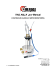
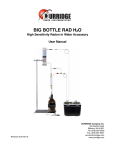
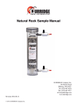
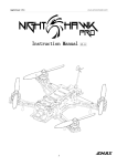
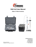
DUTY CYCLE CONTROLLER
CONTENTS
1. Introduction!.......................................................................................3
2. Operating Instructions !.....................................................................3
3. Electrical and Mechanical Specifications!.......................................4
3.1 Electrical Specifications!..............................................................................4
3.2 Mechanical Specifications!...........................................................................4
4. Use with the DRYSTIK and the RAD7!..............................................5
4.1 Soil gas monitoring!......................................................................................5
4.2 Minimum flow rate!........................................................................................6
4.3 Correcting for very low flow rates!...............................................................7
4.4 Thoron!............................................................................................................7
1. Introduction
The DURRIDGE Duty Cycle Controller
controls the on and off time of a DC voltage
powered device, resulting in lower power
usage, lower consumption of consumable
resources, and, in the case of a device with a
pump, lower average flow rate.
The DURRIDGE Duty Cycle Controller
accepts a continually-on supply voltage
between 9-15 VDC and converts it to a
modulated square wave signal.
The duty cycle of a signal is defined as a ratio
of the time the signal is on to the total period
of the cycle (the on and off time combined).
If a signal is continuously on, it has a duty
cycle of 100%
Duty Cycle = (On Time)/(Total Cycle Time)
The DURRIDGE Duty Cycle Controller can
be used in any application where the duty
cycle of a DC power supply needs to be
controlled. The signal is always turned on for
approximately 3 seconds and then turned off
for any amount of time between 0 and 1000
seconds (except when the output is turned
fully off). The output signal can be used to
power any DC powered device which runs on
voltages between 9 and 15 VDC. As the
output signal of the Duty Cycle Controller is
turned on and off, so is the DC powered
device.
2. Operating Instructions
To use the Duty Cycle Controller, plug a DC
power supply or battery (9-15V) into the
“Voltage In” connector on the side of the
Duty Cycle Controller. Use the provided
cable to connect the “Voltage Out” of the
Duty Cycle Controller to the voltage input on
the device to be controlled.
For example, to use the Duty Cycle
Controller to power the DURRIDGE Active
DRYSTIK, the system would be set up as
shown in paragraph 4, page 5.
The Duty Cycle Controller provides a voltage
output almost equal in magnitude to the input
voltage with a selectable duty cycle. The
duty cycle of the output voltage is selected by
the position of the knob on the Duty Cycle
Controller.
©2010, DURRIDGE Company, Inc.
When the knob is turned all of the way to the
right the output will be continually on. When
the knob is turned all the way left the output
will be continually off. In between these two
positions, the duty cycle can be varied
between 100% and 0.3%. The LED on the
front of the Duty Cycle Controller lights up
when the output signal is on.
The behavior of the Duty Cycle Controller for
a setting of 33% duty cycle is shown in
section 3.1, page 4.
Note that the timing will vary slightly with
changes in temperature. Because of this, the
times and duty cycles on the face plate of the
Duty Cycle Controller are approximate. The
user should always note the performance of
the device being controlled and adjust the
Duty Cycle Controller as necessary.
DCC
Page 3
3. Electrical and Mechanical Specifications
3.1 Electrical Specifications
3.2 Mechanical Specifications
Voltage Input (VDC)
9 - 15V
Length (mm/inches)
101 / 3.9
Maximum Output Current (A)
1A
Height (mm/inches)
41 / 1.6
Minimum Operating Temperature (°C)
0 °C
Width (mm/inches)
50 / 2.0
Maximum Operating Temperature (°C)
50 °C
Weight (g/oz)
30 / 4.6
Input Connector is a 2.1mm DC Power Jack
Output Connector is a 3.5mm Tip-Sleeve Jack
©2010, DURRIDGE Company, Inc.
DCC
Page 4
4. Use with the DRYSTIK and the RAD7
4.1 Soil gas monitoring
The duty cycle controller was produced
specifically for long-term monitoring of soil
gas radon concentration with a soil gas probe.
It controls the operation of an active
DRYSTIK in the sample path upstream of a
RAD7 Radon Detector, enabling the average
flow rate to be reduced to such a level that
there is no effect of fresh air diffusing down
through the soil to the sampling point. With
this setup, continuous monitoring of soil gas
from one sample point may be performed
indefinitely. The maximum permissible flow
rate depends on the porosity of the soil and
the depth of the probe.
point. We may then accept that the air at the
sampling point continues to stay very close to
equilibrium with the radium in the soil.
The half life of radon is 3.8 days. The air
sample may be considered to be drawn from a
sphere centered on the sampling point. If that
sphere takes two weeks to grow before it just
touches the ground surface, then it takes two
weeks for air to filter down to the sampling
Maximum flow rate, F, is roughly given by:
©2010, DURRIDGE Company, Inc.
For a probe depth of D cm, the maximum
sphere volume will be 4πD3/3,000 litres. If
the porosity of the soil is 50%, the
corresponding air volume will be 2πD3/3,000.
Two weeks is about 20,000 minutes. So the
average flow rate must be less than
2πD3/60,000,000 litre/min. If we allow that
2π is close to 6, the rate must be less than D3
* 10-7 litre/min where D is the probe depth in
cm.
F = D3 / 107 litre/min
where D is the probe depth in cm
DCC
Page 5
Sphere of soil gas drawn into sampling point.
If, for example, D is about two feet, or 61cm,
the maximum flow rate to meet this criterion
for continuous sampling will be 0.022 L/min.
Uncertainties in the porosity and other
assumptions may make it advisable, for this
depth, to keep the flow rate less than 0.01 L/
min.
the surface. Increasing the depth by 26%, to
77cm, will allow double the flow rate,
assuming uniform soil porosity down to 2m
or so.
Typically, the ON flow rate of an active
DRYSTIK is set to about 0.2 L/min to match
the average flow rate of a RAD7 where the
pump, pumping at 1 L/min, runs for one
minute in every five. So the duty cycle
controller, which is placed between the 12V
supply and the DRYSTIK power input,
should be set to a duty cycle of about 5%, or
an off time of about one minute, to produce
an average flow rate of 0.01 L/min from the
soil gas probe.
Radon has a half life of 3.8 days. If the air
sample takes more than an hour or two to
reach the measurement chamber, there may
be sufficient loss of sample that a correction
for sample decay is called for. With a
laboratory drying unit in the air path, you can
assume a sample path volume of about 2 litres
plus more if the probe is so far from the
RAD7 that the volume of the tubing becomes
significant. If the probe is close to the RAD7,
within 10m, say, and 2 hours is the maximum
acceptable delay before corrections have to be
applied, the minimum permissible flow rate
will be 2L / 120min = 0.016 L/min. At flows
below this rate, a correction factor for radon
decay in the sample may be required.
With a probe depth of 61cm and a porosity of
50%, this setting will enable continuous,
indefinite sampling of the soil gas for radon
concentration without significant dilution of
the sample by fresh air diffusing down from
©2010, DURRIDGE Company, Inc.
4.2 Minimum flow rate
DCC
Page 6
4.3 Correcting for very low flow rates
In the examples above, it may be seen that for
a probe depth of 61cm, to avoid dilution of
the air sample after a week or two of
sampling, a flow rate of no more than 0.01L/
min is desired, but with this flow rate the
sample will lose some radon by radioactive
decay during sample acquisition.
One solution to this problem would be to
increase the sampling depth to 2ft 6inches
(77cm) or more and draw at an average flow
rate of 0.02 L/min. This may be obtained
with a duty cycle of 10% (or OFF times of 27
sec.) on the Duty Cycle Controller and a
DRYSTIK ON flow rate of 0.2 L/min.
Another solution would be to leave the
sampling point at 2ft (61cm), draw at an
average flow rate of 0.02 L/min, take note of
any long-term change in the average after one
week of sampling, and apply a correction for
fresh air infiltration to readings after three or
four weeks of sampling.
A third solution would be to keep the probe at
2ft (61cm) and keep the flow rate at 0.01 L/
min. Assuming a sample volume of 2L, this
will cause an acquisition time of around 2 /
©2010, DURRIDGE Company, Inc.
0.01 min = 200 minutes. In 200 minutes,
about 2.5% of the radon will have been lost
by radioactive decay. A factor of 1.025 may
therefore be applied to the reading to correct
for the loss.
4.4 Thoron
Thoron has a half life of less than a minute.
An active DRYSTIK with Duty Cycle
Controller will, inevitably, cause sample
acquisition delays far in excess of one minute.
Therefore they may not be used for the
measurement of thoron.
To measure thoron in soil gas, the DRYSTIK
may still be used, but the needle valve should
be bypassed and the pump run continuously.
The flow rate will then be close to 1 L/min if
the soil is porous.
At a flow rate of 1 L/min, with a Laboratory
Drying Unit in the sample path, the sample
delay increase over standard thoron protocol
will be about 1 minute, so that the thoron
readings should be multiplied by a factor of 2.
If the flow rate is reduced and/or if the sample
volume is bigger, there will be a bigger
correction factor.
DCC
Page 7