1
3.6.2.Download
3.6.3.Clear APB
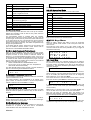
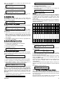
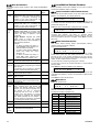
The DOWNLOAD screen allows you to send complete setup and
key database from controller #1 to ALL other controllers in the
network.
Log in and enter MAINTENANCE menu.
Scroll down to DOWNLOAD and press Enter.
Wait until screen goes back to MAINTENANCE menu.
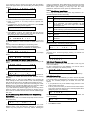
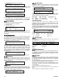
The CLEAR APB screen allows you to reset all anti-passback key
counters. When a key is presented to a reader whose controller is
configured for anti-passback, it sets off an anti-passback period
defined in half-hours in MISC SETUP.
Clearing the counter table with CLEAR APB, will cause the
controller to accept ALL keys again from any of the readers.
Please note that the counter table can also be cleared
automatically one time every day by setting the APB RESET
HOUR in LOCAL SETUP to a number in range of 0 (midnight)
through 23 (11pm at night).
D O WN L O A D
S E T U P
4.OPERATING MODES
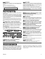
The AXS-100 controller network can function in a loop wide antipassback mode:
This mode causes controllers #1 through #8 to share tag entry
and exit events. To achieve this, you need to set each controller
to any of the anti-passback modes detailed below and set flag 8
in FLAGS SET #2 screen (see sec. 3.2.8.2.Anti-Passback
Duration). This operation is specific to each controller and is NOT
transmitted to all controllers.
For hard anti-passback, an exit must follow each entry (for reentry to occur). An entry must follow an exit (for re-exit to occur).
For soft anti-passback, an exit must follow each entry (for re-entry
to occur), but unlimited exit may occur several times without reentry.
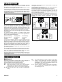
4.1.Single Door with Two Readers
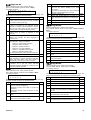
There are three modes dealing with a single door and two readers.
In these modes, the door number is the odd number for this
controller, i.e. door #1 for controller #1, door #3 for controller #2.
Note: The Magnetic Lock (Maglock) or Electro-Magnetic Door
Strike (EMS) has to be connected to left side door connector!
The three modes are:
4.1.1.Single door, without Anti-passback
The two readers control a single door, one within and the other,
outside of the secured area. This is mode 2.
ENTER
ENTER PASSWORD
XXXX
>SETUP
ENTER Enter
EDIT KEYS
ENTER
ENTER
ENTER
EDIT REGISTERS
>LOCAL SETUP
ENTER
ENTER
Any exit has to be preceded by an entry. Every entry has to be
preceded by an exit. This is mode 6.
4.2.Two Doors
The “Two Doors” mode is the most common operating mode, in
which two doors’ locks are controlled by each controller. Each of
the two doors is controlled separately. Controller #1 controls
doors #1 and #2, controller #2 controls doors #3 and #4, etc.
4.2.1.Two doors without Anti-passback
This mode allows the connection of two separate doors or gates
without the anti-passback feature. There is no interaction
between the two locks. This is mode 7 and is the factory default.
4.2.2.Two doors, with Anti-passback in both
directions (Soft Anti-Passback)
This mode allows the connection of two separate doors or gates
with the anti-passback feature. Lock #1 (left side) is used for entry
and lock #2 (right side) is considered as the exit. This is mode 3.
4.2.3.Two doors, with Anti-passback for
entry only (Hard Anti-Passback)
This mode allows the connection of two separate doors or gates
with the anti-passback feature. Any exit has to be preceded by an
entry. Every entry has to be preceded by an exit. This is mode 1.
4.2.4.Two doors, entry only Anti-passback
Default is 2975
>DATE TYPE
DATE/TIME
4.1.3.Single door, with Anti-passback in both
directions (Hard Anti-Passback)
MODE
7
ENTER
ENTER
APB RESET HOUR
99:00
EDIT REGISTERS
>LOCAL SETUP
Mode is from 1 to 9
(9 represents
elevator control)
4.1.2.Single door, with Anti-passback for
entry only (Soft Anti-Passback)
Multiple exits are allowed, but only a single entry is allowed until
the key is presented to the inside reader. This is mode 4.
The two doors are for entry only. The Anti-passback will work with
the other controller [controllers #1 to #8] on the loop that is set to
mode 5. This is mode 8.
4.2.5.Soft Anti-Passback use loop with mode
8 as entry
The two doors are for exit only.
This is mode 5.
Note: 4.2.4 and 4.2.5 can operate together as entry and exit, and
together with all other modes within a loop.
4.2.6.Elevator control
Elevator control using IOX-4 add-on cards. This is mode 9.
For full description, refer to the IOX-4 user manual.
5.ADVANCED FEATURES
The AXS-100 user interface allows for advanced features and
also lets the user make shortcuts in certain situations for
speeding up data entry. All hidden features are accessed by
pressing the UP ↑ and DOWN ↓ arrow buttons. The UP ↑ arrow,
where available, lets you reach data entry screens for extra
features. The DOWN arrow, where available, acts like the Enter
button (execute function) but executes the same function again.
DE6280U
This allows for fast adding or modifying of keys. The following
sections list the extra functions available using the UP and
DOWN arrow buttons modification of many keys without the need
to press any button.
11