1
WEB CONTROL PRODUCTS
User Manual
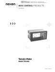
Open Loop Tension Controller
TCD 600
FORM NO. L-20348-F-0705
In accordance with Nexen’s established policy of constant product improvement, the specifications contained in this
manual are subject to change without notice. Technical data listed in this manual are based on the latest information
available at the time of printing and are also subject to change without notice.
Technical Support:
800-843-7445
(651) 484-5900
www.nexengroup.com
DANGER
Read this manual carefully before installation and operation.
Follow Nexen's instructions and integrate this unit into your system with care.
This unit should be installed, operated and maintained by qualified personnel ONLY.
Improper installation can damage your system or cause injury or death.
Comply with all applicable codes.
Nexen Group, Inc.
560 Oak Grove Parkway
Vadnais Heights, Minnesota 55127
ISO 9001 Certified
Copyright 1999 Nexen Group, Inc.
FORM NO. L-20348-F-0705
2
Table of Contents
INTRODUCTION --------------------------------------------------------------------------------------------------------------------------- 1
INSTALLATION ----------------------------------------------------------------------------------------------------------------------------- 2
PANEL DIMENSIONS AND MOUNTING INSTRUCTIONS -------------------------------------------------------------- 2
ELECTRICAL CONNECTIONS ------------------------------------------------------------------------------------------------------ 4
GLOSSARY OF TERMS ---------------------------------------------------------------------------------------------------------------- 7
SETUP PROCEDURE ------------------------------------------------------------------------------------------------------------------- 8
Machine ---------------------------------------------------------------------------------------------------------------------------------- 9
Job ------------------------------------------------------------------------------------------------------------------------------------------ 9
Calibration ------------------------------------------------------------------------------------------------------------------------------11
QUICK REFERENCE SETUP AND CALIBRATION WORKSHEET --------------------------------------------- 13-15
OPERATION --------------------------------------------------------------------------------------------------------------------------------16
Overview --------------------------------------------------------------------------------------------------------------------------------16
Loading a Job --------------------------------------------------------------------------------------------------------------------------17
Automatic Operation ----------------------------------------------------------------------------------------------------------------17
Manual Operation --------------------------------------------------------------------------------------------------------------------17
Unwind Application ------------------------------------------------------------------------------------------------------------------18
Winding Application ----------------------------------------------------------------------------------------------------------------18
SPECIFICATIONS ------------------------------------------------------------------------------------------------------------------------19
PARTS LIST ---------------------------------------------------------------------------------------------------------------------------------19
SERVICE INSTRUCTIONS -----------------------------------------------------------------------------------------------------------19
WARRANTY ------------------------------------------------------------------------------------------------------------------------------- 20
3
FORM NO. L-20348-F-0705
INTRODUCTION
The Nexen TCD 600 is a non-contact open loop tension
control system that provides reliable web tension control
that’s easy-to-use and requires minimum attention by the
operator.
SENSOR
The TCD 600 maintains constant tension by varying the brake
or clutch torque with the change in roll diameter. When the
set point is adjusted for the maximum torque needed at full
roll diameter, the TCD 600 applies a correction based on
its diameter calculation and proportionately increases clutch
torque as a wind roll builds up, or decreases brake torque
as an unwind roll becomes smaller.
BRAKE
OR CLUTCH
TCD 600
FIGURE 1
For example, Figure 1 shows a system that includes a sensor,
which measures the diameter of the roll. The sensor sends
this information to the TCD 600 Controller. An operator
enters into the TCD 600 the maximum and minimum size
of the roll, along with other information that applies to the
specific job. The TCD 600, using this information, varies
the amount of torque applied to a brake or a clutch as the
roll diameter changes. As a result, a constant tension is
maintained on the web. This example is only one of the
many potential control systems that can be built around
the TCD 600.
Output to brake for Unwind
applications, or to clutch for
Wind applications.
ULTRASONIC
SENSOR
FIGURE 2
The TCD 600 will work with three different sensor configurations: Ultrasonic Sensor, Proximity Switch, and Proximity
Switch - Optical Encoder combination. The Ultrasonic Sensor
configuration measures roll diameter directly (See Figure 2).
The Proximity Sensor configuration counts the number of roll
revolutions. This value, plus the web thickness, enables the
TCD 600 to estimate the roll diameter (See Figure 3). The
Proximity Switch - Optical Encoder combination accurately
calculates the roll diameter by measuring the amount of web
paid out for each revolution of the roll.
TARGET
PROXIMITY
SWITCH
The TCD 600 provides three output signals: two for control,
4-20 mA and 0-10 VDC, and one for monitoring, 0-5 VDC. The
4-20 mA output signal is typically used with Nexen ElectroPneumatic Converters to vary the air pressure applied to air
actuated tension brakes and clutches. The 0-10 VDC output
signal is often used as a speed or torque reference voltage
for motor drive controllers or is used with power supplies
for electric brakes or clutches. The 0-5 VDC output signal
provides a way to remotely monitor roll diameter; 0 VDC
corresponds to the roll core, and 5 VDC corresponds to a
maximum diameter roll. In addition, two contact outputs are
available for use as user specified minimum and maximum
roll diameter alarm outputs.
FIGURE 3
OPTICAL
ENCODER
TARGET
PROXIMITY
SWITCH
FIGURE 4
FORM NO. L-20348-F-0705
4
INSTALLATION
CONTROLLER POSITIONING
The TCD 600 Controller should be mounted in a location that will allow convenient use for the operator.
CAUTION
The TCD 600 is an electronic component and should be mounted in a shock and vibration free area which has
an ambient temperature of less than 120o F [50o C] and more than 32o F [0o C].
PANEL DIMENSIONS AND
MOUNTING INSTRUCTIONS
.50 In.
[13 mm]
7.25 In.
[184 mm]
1
3.77 In.
[96 mm]
5
2
4
.75 In.
[19 mm]
3
7.56 In.
[192 mm]
7.28 In.
[185 mm]
PANEL CUTOUT
Dimensions
CONTROL PANEL
BEZEL
3.63 In.
[92 mm]
PANEL MOUNTING INSTRUCTIONS
1
Remove the Retaining Screw with a 1/16" Allen wrench.
2
Pull the Slide Bars (on both sides) off the Case.
3
Slide the Case through the cutout in the control panel.
4
Push the Slide Bars back into the grooves of the Case.
5
Reinstall the Retaining Screws and tighten to squeeze
the Control Panel between the Slide Bars and the TCD
600 Bezel.
MOUNTING BRACKET DIMENSIONS
.203Ø
2.0 In.
[51 mm]
Desktop Configuration
1.0 In.
[26 mm]
5.31 In.
[135 mm]
4.63 In.
[118 mm]
Wall Mount Configuration
FIGURE 5
.203Ø
(Screws Provided)
4.0 In.
[102 mm]
7.3 In.
[186 mm]
(continued...)
5
FORM NO. L-20348-F-0705
INSTALLATION (continued...)
SENSOR MOUNTING
An Ultrasonic Sensor can measure the change in roll radius
by bouncing soundwaves off the material, enabling the
TCD 600 to calculate roll diameter. For calibrations to be
accurate, the sensor must be installed perpendicular to
the axis of the wind or unwind shaft. Also, the Ultrasonic
Sensor must be mounted at least four inches [100mm]
away from the maximum diameter roll.
Ultrasonic Sensor
4" [100mm]
Minimum
40" [1,000mm]
Maximum
ADJUSTMENT OF THE ULTRASONIC SENSOR
Nexen's Ultrasonic Sensor is factory adjusted for a 4 to 40
inch range and typically does not require re-adjustment prior
to use. If a shorter range is desired, then re-adjustment may
be performed by connecting a voltmeter to the sensor's
output and turning P1 for the near point adjustment and P2
for the far point adjustment. (See figure 6) Adjust P1 and
P2 until the output voltage covers as much of the 0 to 10
VDC range as possible over the desired distance.
ADJUSTING
SCREWS
P2
P1
NOTE: The indicator on the end of an Ultrasonic Sensor
shows an indication of signal strength. The indicator
will light GREEN when a target is out of range, and
fades to RED as a target moves into range, depending on how much reflected signal it receives from a
target.
(Far Point
Adjustment)
(Near Point
Adjustment)
Green-Red
Indicator
FIGURE 6 - Ultrasonic Sensor
A Proximity Switch (See Figure 7) is designed to count
revolutions as the roll turns by sensing an iron or steel
target once every revolution. Mount the Proximity Switch
to a secure, nonrotating member and set the gap between
the Nexen Proximity Switch and the target to .20 to .40
inch (5.1 - 10.3mm).
TARGET
GAP
The target must be large enough to trigger the switch and
can be mounted to the roll shaft or any other mechanical
component that rotates at the same speed as the roll.
PROXIMITY
SWITCH
When using an Optical Encoder along with a Proximity
Switch (See Figure 8), precise diameter measurement of
the roll can be achieved.
FIGURE 7
The Optical Encoder is coupled to a measuring wheel
which, when rotated one full turn, equals 12 inches. The
Optical Encoder translates this rotation into 100 pulses per
foot. As a result, the Optical Encoder must be mounted
so as to ensure that the measuring wheel rotates at the
same speed as the web moving through the machine. A
good mounting location would have the measuring wheel
making contact with one of a pair of nip rollers, because
the pressure between these rollers ensures that there
will be no slippage between the web surface and the roll
surface. However, the wheel should NOT make direct
contact with the web as that might scratch or mar the
surface of the web.
FORM NO. L-20348-F-0705
MEASURING WHEEL
OPTICAL
ENCODER
NIP ROLLER
TARGET
PROXIMITY
SWITCH
FIGURE 8
6
ELECTRICAL CONNECTIONS
Refer to Figure 10A and 10B for all electrical connections.
WARNING
Before connecting any wires, be sure that AC
power is turned off, locked and proper signage
applied according to safety regulations. All
wiring must be shielded or run through
conduit. Wire runs are to be no more than 300
feet. Connect all wires to the terminal strip on
the back panel of the TCD 600 (See Figure 9).
Avoid splicing wires.
All wires to be inserted into the modular connectors must
be prepared ahead of time by stripping the insulation
1/4" from the end of the wire (See Figure 9). Twist the
end of each wire to be sure there are no loose or frayed
strands. Unplugging the modular connectors will make
wiring easier.
CAUTION
Wires must be stripped to the proper length to
avoid electrical shorting.
CAUTION
After making all the connections, double-check each one
for accuracy and clamping tightness.
Observe polarity when connecting any devices
marked + and -.
Apply AC power.
CAUTION
Make sure the AC Select Switch is in the proper
position, or damage could result to the TCD 600
(See Figure 9).
STRIP INSULATION 1/4" BACK FROM END OF WIRE
1/4"
AC Select Switch
1
2
3
4
5
6
7
8
9 10 11
12 13 14 15 16 17
115/230 VAC
60/50Hz
30VA Max
115V
4
L1 L2
22 23 24 25 26 27 28
18 19 20 21
29 30 31 32 33 3
FIGURE 9 - BACK PANEL ELECTRICAL CONNECTIONS
(continued...)
7
FORM NO. L-20348-F-0705
ELECTRICAL CONNECTIONS
(continued...)
ELECTRICAL CONNECTIONS
(TCD 600 Back Panel)
L1 L2
115/230 VAC
Neutral/230 VAC
Earth Ground
To EN40 or EN50
{
+
-
- Minimum Diameter Alarm
+ Maximum Diameter Alarm
- Maximum Diameter Alarm
Not Used
Not Used
See
Note 2.
Blac k, Signal
White, Signal
Blac k, Com
Shield
o
o
Remote Start
o
o
Remote Stop
o
Remote
Hold/ Resume
o
Notes: 1. See Alarm Output Connection Diagrams on page 6.
2. Remote contact closures are momentary only.
3. Shield all signal wiring and keep away from wires carying
heavy loads or AC supply power.
FIGURE 10A
(continued...)
FORM NO. L-20348-F-0705
{
Blue, Com
8
12 13 14 15 16 17
See
Note 1.
Brown, +15 VDC
Not Used
29 30 31 32 33 34
+ Minimum Diameter Alarm
{ Red, +24 VDC
9 10 11
0 - 5 VDC
Roll Diameter
Output
To
Ultrasonic
Sensor
Blac k
8
Not Used
{
Red
7
Shield
.
6
Brown, Signal
To
Pro ximity
Sensor
-
.
5
{
Blac k, Common
To Ultrasonic
Sensor
22 23 24 25 26 27 28
To
Nexen
Encoder
Red, +15 VDC
{
{
+
4
Not Used
4-20 mA DC
Control Output
Com
3
Shield
{
+15 VDC
2
-
External Power Supply
Input for Isolated Control
Output Signals
1
+
18 19 20 21
{
0 - 10 VD C
Control
Output
ELECTRICAL CONNECTIONS
(continued...)
TCD 600 ALARM OUTPUT CONNECTION DIAGRAMS
User Supplied
VDC (See Specifications for
maximum voltage.)
R (See Note.)
TCD 600
29/31
To PLC Input
30/32
VDC Common
User Supplied
NOTE: The minimum value of resistor (R) is 10 x VDC.
Alarm Output Tied to PLC Input.
User Supplied
External Indicator
(See Note.)
TCD 600
29/31
R
VDC
(See Specifications for
maximum voltage.)
30/32
VDC Common
User Supplied
NOTE: The minimum value of Resistor (R) is equal to VDC
divided by the maximum current limit of the Indicator.
Alarm Output Tied to External Indicator
User Supplied
TCD 600
29/31
(See Notes.)
External
Coil
VDC
1N4002
30/32
(See Specifications for
maximum voltage.)
VDC Common
User Supplied
NOTES: 1. Be sure the current requirement of the External Coil does not
exceed the capability of the alarm output (
2. Any inductive load, such as a relay coil, must have a 1N4002,
or equivalent, diode across it as shown.
FIGURE 10B
Alarm Output Tied to External Inductive Coil
9
FORM NO. L-20348-F-0705
TCD600 ISOLATED OUTPUTS
The 0 -10 VDC and 4 - 20 mA tension control outputs can be isolated from the TCD600's power supply. This is often
done when connecting the outputs to a motor drive system or whenever there is a concern about ground loops causing electrical noise problems. A 15 VDC power supply is required and connects to terminal block positions 1 and 2,
see figure 10A. The TCD600 is shipped in the non-isolated setting. Two internal jumpers, JP1 and JP2, must be set
before the control outputs can be isolated. Refer to the following procedure to change the setting.
Note: Only the tension control outputs can be isolated. The diameter output signal can
not be isolated from within the TCD600.
Changing the Output Isolation Setting
1.
Disconnect all electrical power from the TCD600.
2.
Remove all terminal block plug connectors from the
back of the TCD600.
3.
Remove six fasteners from the back nomenclature
panel.
4.
Remove the upper left hand fastener from the front
membrane switch panel. (See figure 10C)
5.
Pull the top panel of the enclosure toward the back
until it is completely removed.
6.
Locate JP1 and JP2 on the printed circuit board.
7.
Set the jumpers for the desired setting.
(See figure 10D.)
8.
Replace the top cover, back nomenclature panel and
all fasteners.
9.
Plug the connectors back into the terminal blocks.
10.
Connect the 15 VDC power supply to terminal block
terminals 1 and 2.
(Terminal 1: +15 VDC
11.
FIGURE 10C
JP1
Non-Isolated
Outputs
Terminal 2: DC common)
JP1 JP2
Reconnect electrical power to the TCD600.
FIGURE 10D
FORM NO. L-20348-F-0705
JP2
10
JP1
JP2
Isolated
Outputs
GLOSSARY OF TERMS
Sonic
Ultrasonic Sensor
Prox
Proximity Sensor
Prox Encod
Proximity Sensor-Encoder combination
Counts
For Prox encoder combination only, counts represent the number of pulses generated by the encoder during 100 inches of web travel.
Full Roll
Diameter of the largest roll used within the range of 0 to 70 inches (0 to 1778 mm).
Setpoint
Percentage of controlled output applied to the brake, clutch or drive at full roll diameter; Setpoint adjustment range is 0 to 100%.
Hold Torque
Percentage of controlled output used in several different ways. For Unwind applications, when the web is
not moving, it is used to apply a constant output which holds the roll stationary and prevents slack webs.
At the beginning of a run, Hold Torque is maintained for the duration of Start Time, enabling the process
to have a lower brake torque as the roll is accelerating. For Wind applications, Hold Torque provides sufficient torque during Start Time to enable the winding process to begin. Hold Torque adjustment range is 0
to 100%.
Strt Time
(Start Time) During Start Time, the TCD 600's output is determined by the Hold Torque Value. This value is
maintained for the duration of the Start Time period, enabling the process to have a lower torque while the
roll is accelerating, thus providing a smooth startup of the process and preventing web breaks. Start Time
has an adjustment range of 0 to over 200 seconds.
Taper
Used only in Wind applications, Taper starts the roll, at core, with a higher tension value, then automatically
decreases this tension as the roll diameter increases. Taper affects the original Setpoint value by gradually taking away from the Setpoint a percentage of its value. The amount of Taper can be adjusted within a
range from 0 to 86.5%.
Stop Mult
(Stop Multiplier) During a stop cycle of an Unwind application, the current output value is multiplied to
produce sufficient torque to completely stop a roll. The Stop Multiplier can be adjusted to a value from 1 to
9.9.
Stop Time
Stop Time is the length of time that the Stop Multiplier Torque value is applied, and can be adjusted from 0
to over 200 seconds.
Diam Hyst
(Diameter Hysteresis) This feature is used to enable the TCD 600 to ignore the changes in roll radius created by out-of-round or egg-shaped rolls. The Diameter Hysteresis can be adjusted from 0 to 2.55 inches
(0 to 25.5 mm).
Idiam
(Initial Diameter) This is used with Proximity Sensor only systems for both Wind and Unwind applications.
This value is the actual diameter of the roll or core at the start of a job, and must be entered to ensure
proper operation. The value of Idiam can be adjusted from 0 to 650 inches (0 to 6500 mm).
Thick
Web thickness -- also used with Proximity Sensor only systems. The TCD 600 uses the Initial diameter and
the Thickness to estimate the roll's diameter by subtracting or adding one "thickness amount" for every
revolution of the roll. Thick can be adjusted from 0 to 1.0 inches (0 to 25.4 mm).
Min Dia Alrm
(Minimum Diameter Alarm) This is used for Unwind applications where an alarm output is triggered when
the roll size has decreased to a specified diameter; adjustment range is 0 to 650 inches (0-6500mm).
Min Alarm: [NC] NO
Minimum Alarm Configuration; Minimum Diameter Alarm output can be configured for Normally Closed
(NC) or Normally Open (NO) operation.
Min Out
Minimum Output is used only for Wind applications that use a clutch. This feature sets a minimum output
level to overcome the mechanical force of the clutch for engaging.
Max dia Alrm
(Maximum Diameter Alarm) This is used for Wind applications where an alarm output is triggered when the
roll size has increased to a specified diameter; its adjustment range is 0 to 650 inches (0-6500mm).
Max Alarm: [NC] NO
Maximum Alarm Configuration; Maximum Diameter Alarm output can be configured for Normally Closed
(NC) or Normally Open (NO) operation.
Accept Changes Y [N]
After entering in new information, the TCD 600 will ask if the changes should be accepted; select Yes (Y)
or No (N).
11
FORM NO. L-20348-F-0705
SETUP PROCEDURE
The front panel of the TCD 600 has nine function buttons and a two-line display (See Figure 11).
The TCD 600 has a feature that locks out access to certain setup and calibration functions. Upon powering up, the operator
has access to the Standby Mode, Run Mode, and the Setup Mode. To gain full access for setting up and calibrating,
press the Nexen Logo button while simultaneously pressing the Stop button and hold them until SETUP ENABLE
appears on the display. Full access allows changes to be made to the Machine parameters and sensor calibration. This
access is allowed until the unit is powered down or until the same key sequence is repeated.
Pressing the Select Upper button causes the top line of the display to step through the operation modes - Run Mode,
Setup Mode, Calibration Mode and back to Standby Mode.
Pressing the Select Lower button, while in the Standby Mode, will enable you to quickly view the parameter settings of
the current loaded job. These settings cannot be changed while in the Standby Mode.
Pressing the Select Lower button, while in Automatic Run Mode, will enable you to view and change the following job
parameters: Setpoint, Taper %, and Diam Hyst (Diameter Hysteresis).
Pressing the Minus and Plus buttons enables you to select values while in Run Mode, Setup Mode, and Calibration Mode.
Selected values are displayed inside brackets ( [ ] ).The Enter button is used to enter values (or customized settings) into
the TCD 600's’ memory.
Pressing the Output button toggles on and off the output signal being sent from the TCD 600 to a Motor Controller or a
pneumatic device for clutches and brakes. During the Setup and Calibration Modes, you may want to keep the Output
turned Off. Also, to allow free movement, the Output should be Off whenever a roll is being changed.
The rest of the buttons will be explained in the RUN MODE section of this manual.
Parameter default settings for Wind and Unwind applications are listed on the Quick Reference Worksheets on Pages 13
- 15. The Worksheets also provide space for you to write in your own settings; this can be useful during Setup.
The parameters for the Setup and Calibration Modes must be set to the specifications of the job to be run: first, in Setup
Mode, enter the Machine parameters; next, the Job parameters; and finally in Calibration Mode, enter the Calibration
Mode parameters.
SELECT
UPPER
BUTTON
NEXEN
LOGO
BUTTON
2-LINE DISPLAY
SELECT LOWER
BUTTON
STOP
BUTTON
OUTPUT
BUTTON
FIGURE 11
STANDBY MODE
Nexen TCD
MINUS/LEFT SHIFT
BUTTON
(OFF)
Rev
PLUS/RIGHT SHIFT
BUTTON
ENTER
BUTTON
(continued...)
FORM NO. L-20348-F-0705
START
BUTTON
12
HOLD/RESUME
BUTTON
SETUP PROCEDURE (continued...)
SETUP MODE - MACHINE SETUP
NOTE: To gain access to Machine setup, press the Nexen logo
button while simultaneously pressing the STOP button and
hold them until SETUP ENABLE appears on the display.
1.
Press the Select Upper button until you reach Setup
Mode (See Figure 12). The parameters in Setup Mode
are set when the machine is initially installed or when the
machine is modified. Press the plus or minus buttons to
select Machine. Then press Enter.
2.
The lower display line will advance to Language (See
Figure 13). Press the plus or minus button to select the
desired language, then press Enter.
3.
The lower display line will advance, prompting you to
select millimeters or inches (See Fig. 14). Press the plus
or minus button to select the desired measurement; then
press Enter.
4.
The lower display line will advance, prompting you to
select wind or unwind (See Figure 15). Wind controls
tension during the increase in the diameter of a roll,
and Unwind controls tension during the decrease in the
diameter of a roll. Press the plus or minus button to select
WIND or UNWIND, then press Enter.
5.
SETUP MODE
(OFF)
Job
[Machine]
FIGURE
Minus
Enter
Plus
SET MACHINE
(OFF)
Language:
English
FIGURE 13
SET MACHINE (OFF)
Millimeters
[Inches]
The lower display line will advance, prompting you to
select the type of sensor to be used. The selections are
Sonic, which stands for Ultrasonic Sensor; Prox, which
stands for proximity sensor, or Prox-Encod, which stands
for Proximity Sensor - Optical Encoder (See Figure 16).
Press the plus or minus button to select the proper type of
sensor, then press Enter.
FIGURE 14
SET MACHINE
(OFF)
[WIND]
UNWIND
NOTE: When the Prox-Encod combination is selected, the
lower display will advance, revealing the following (Counts:
00833/100 in [2540mm]). If you are using a Nexen Optical
Encoder this information is the Factory default setting, and
you can proceed to the next step by pushing Enter. If you
are using another Optical Encoder you will have to calculate
the number of pulses per 100 in [2540mm] of web length
and replace the default value (00833) with your calculated
value.
FIGURE 15
Example: The Nexen Optical Encoder is attached to a 12in
[305mm] circumference wheel. This wheel contacts a roller
that is moving at the same speed as the web. For every 12
in [305mm] of web that passes by, the Encoder produces
100 pulses. Use the following formula to calculate the new
number: (100 multiplied by number of pulses per revolution
of the encoder) divided by the number of inches of web length
per revolution of the encoder.
SET MACHINE
[Sonic]
Prox
(OFF)
Encod
FIGURE 16
Example: (100 in. [2540mm] x 100 pulses per rev.) / 12 inches
[305mm] per rev. = 00833.
SET JOB
[Edit]
Press the plus or minus buttons to change the default value
to your calculated value, then press Enter. The upper display
line will now return to the Setup Mode.
(OFF)
Load Save
FIGURE 17
(continued...)
13
FORM NO. L-20348-F-0705
SETUP PROCEDURE (continued...)
SETUP MODE - JOB SETUP
1.
2.
Press the minus button to select Set Job, then press Enter.
The upper display line changes to Set Job and the lower
display line allows you to select Edit, Load or Save (See
Figure 17). Select Edit and press Enter.
EDIT JOB
(OFF)
Full Roll: 060.00 in
The upper line advances to Edit Job. The lower line,
displaying Full Roll, will scroll though a list of parameters
that can be set for the specific job (See Figure 18). For
example, to change the value of the Full Roll parameter,
press the plus or minus buttons to set the size of the full
roll diameter. Then press Enter and the next parameter will
appear on the lower line, which will be Setpoint.
FIGURE 18
EDIT JOB
(OFF)
Accept Changes [Y] N
Use the Quick Reference Worksheets on Pages 13 -15 to
enter the settings for the rest of the parameters. For explanations of the parameters see the Glossary of Terms.
3.
After stepping through and setting all of the parameters, you
are then prompted to accept the changes you have made
(See Figure 19). If you are not ready to accept them or
want to reset the parameters to default values, select N for
no and press Enter. You will be returned to the beginning of
the Set Job Mode.
FIGURE 19
SET JOB
(OFF)
Edit
Load
[Save]
If you are ready to accept the changes you have made,
select Y for yes and press Enter. The display will return to
the Set Job Mode.
4.
The TCD 600 can store up to 5 different jobs into memory.
Press the plus or minus button to select Save, then press
Enter (See Figure 20).
5.
Using the plus or minus button, select the number for the
job that is to be saved. Choose from Job 1 through Job 5,
then press the Enter button (See Figure 21).
6.
The display will prompt you to overwrite any previous job
you may have entered (See Figure 22).
7.
Press the plus or minus button to select Y for yes, then
press Enter and the display will confirm the save (See Figure 23).
FIGURE 20
SAVE JOB AS . . .
Job 1
FIGURE 21
Overwrite?
Y
[N]
Job 1
FIGURE 22
Overwrite?
[Y]
N
Job 1 Saved!
FIGURE 23
(continued...)
FORM NO. L-20348-F-0705
14
SETUP PROCEDURE (continued...)
8.
9.
The display returns to Set Job. Press EDIT again to edit
JOB 2, and repeat this procedure up to JOB 5 if needed.
Or, press Load to recall previously saved job settings to
use for a job you want to run now. Press the plus or minus
button to select Load, then press Enter (See Figure 24).
SET JOB
Edit
[Load]
You can then choose to load either the default job or any of
5 previously saved jobs. Press the plus or minus button to
select the desired job (See Figure 25), then press Enter;
the display will confirm that the selected job is loaded, then
it will return to the Set Job Mode.
FIGURE 24
LOAD JOB
(OFF)
Default Job
Calibration Mode
NOTE: Diameter calibration for the ultrasonic sensor, is
only required for the initial setup of the machine, or if
the ultrasonic sensor has been moved.
FIGURE 25
To gain access to Machine setup and diameter calibration, press the Nexen logo button while simultaneously
pressing the STOP button and hold them until SETUP
ENABLE appears on the display (See Figure 11).
1.
2.
Using the Select Upper button, advance the top line of the
display to Calibration Mode (See Figure 26). Using the
plus or minus buttons, select Edit, then press the Enter button.
4.
5.
(OFF)
Default
CAL MODE
[Diam]
(OFF)
Diam will appear in the display (See Figure 27). Press
Enter.
Slide an empty core onto the roll shaft, so it is seen by the
Ultrasonic Sensor.
FIGURE 27
CAL DIAMETER, Core Diam: will appear in the display
(See Figure 28). Using the plus or minus button, enter desired core diameter, then press the Enter button. Computing will appear in the display for a few seconds, then the
display will advance to the next step (See Figure 29).
CAL DIAMETER
(OFF)
Core Diam: 001.00 in
Remove empty core, slide on a maximum-diameter roll so it
is seen by the Ultrasonic Sensor.
FIGURE 28
Rolls of less than the maximum diameter can be used. In
these instances, enter the actual diameter when prompted
for Max Diam.
6.
CAL MODE
[Edit ] or
FIGURE 26
NOTE: The following procedure (Steps 3-6) applies only to the
Ultrasonic Sensor. Advance to Step 7 to calibrate a Proximity
Switch Sensor or Proximity Switch-Encoder sensors.
3.
(OFF)
Save
CAL DIAMETER, Max Diam: will appear in the display (See
Figure 30). Using the plus or minus button, enter the maximum roll diameter then press the Enter button. Computing
will appear in the display for a few seconds (See Figure
29), then the display will return to the CAL MODE (See
Figure 26). Advance to Step 11 to enable lockout.
CAL DIAMETER (OFF)
Computing
FIGURE 29
(continued...)
15
FORM NO. L-20348-F-0705
SETUP PROCEDURE (continued...)
CALIBRATION MODE - (continued...)
NOTE: The following procedure is for either the Proximity
Switch system or the Proximity Switch-Encoder system.
7.
CAL DIAMETER, Core Diam: will appear in the display
(See Figure 28). Using the plus or minus button, enter the
desired core diameter then press the Enter button.
8.
CAL DIAMETER, Max Diam: will appear in the display
(See Figure 30). Using the plus or minus button, enter the
desired maximum diameter then press the Enter button.
CAL DIAMETER
(OFF)
Max Diam: 060.00 in
FIGURE 30
NOTE: Minimum Output is used only for Wind applications
that use air-actuated clutches. This feature enables you to
adjust the minimum TCD 600 output needed to overcome the
mechanical characteristics of the clutch; e.g., a release spring.
If not used, advance to step 11 to enable lockout.
9.
CAL MODE
Diam
CAL MODE, Diam [Min Out]: will appear in the display
(See Figure 31). Using the plus or minus button, select Min
Out then press the Enter button.
FIGURE 31
10. CAL MIN OUT, Min Output: will appear in the display (See
Figure 32). Using the plus or minus button, adjust the
output until the clutch is fully engaged, then decrease the
value until the clutch is slightly disengaged and press the
Enter button.
CAL MIN OUT
(OFF)
Min Output: 000.0%
11. After calibration is completed, simultaneously press and
hold the Nexen and Stop buttons for 3 seconds to enable
the lockout feature and prevent any unintended changes to
the calibration settings.
FORM NO. L-20348-F-0705
(OFF)
[Min Out]
FIGURE 32
16
QUICK REFERENCE SETUP AND CALIBRATION WORKSHEET
DEFAULT
JOB 1
JOB 2
JOB 3
JOB 4
JOB 5
SETUP MODE [Set Machine]
*
Language:
English
Millimeters
Inches
Inches
Wind
Unwind
Wind
Sonic
Prox
Prox Encod
Counts: (For Prox and Prox Encod Sensors Only)
English
Sonic
00833/100 in
SETUP MODE [Set Job]
Wind Applications, Sonic Sensor
[Edit Job] (Parameters)
Full Roll:
060.00 in
Setpoint:
010.0 %
Hold Torque:
010.0 %
Strt Time:
003.0 sec
Taper:
000.0 %
Diam Hyst:
Min Dia Alrm:
Min Alarm:
Max Dia Alrm:
Max Alarm:
Accept Changes (Yes or No)
0.10 in
006.00
NC
050.00
NC
Y [N]
Wind Applications, Prox Sensor
[Edit Job] (Parameters)
Full Roll:
060.00 in
Setpoint:
010.0 %
Hold Torque:
010.0 %
Strt Time:
003.0 sec
Taper:
000.0 %
IDiam:
006.00 in
Thick:
0.0050 in
Min Dia Alrm:
006.00
Min Alarm:
Max Dia Alrm:
Max Alarm:
Accept Changes (Yes or No)
NC
050.00
NC
Y [N]
* Additional Languages include Spanish and French; other languages may be included later; contact Nexen for details.
Note: Refer to Glossary of Terms for explanations of the parameters.
17
FORM NO. L-20348-F-0705
QUICK REFERENCE SETUP AND CALIBRATION WORKSHEET
DEFAULT
JOB 1
JOB 2
Wind Applications, Prox Encod Sensor
[Edit Job] (Parameters)
Full Roll:
060.00 in
Setpoint:
010.0 %
Hold Torque:
010.0 %
Strt Time:
003.0 sec
Taper:
000.0 %
Diam Hyst:
010.0 in
Min Dia Alrm:
006.00
Min Alarm:
NC
Max Dia Alrm:
050.00
Max Alarm:
NC
Accept Changes (Yes or No)
Y [N]
Unwind Applications, Sonic Sensor
[Edit Job] (Parameters)
Full Roll:
060.00 in
Setpoint:
010.0 %
Hold Torque:
010.0 %
Stop Mult:
01.0X
Stop Time:
003.0 sec
Start Time:
003.0 sec
Diam Hyst:
0.10 in
Min Dia Alrm:
006.00
Min Alarm:
[NC] NO
Max Dia Alrm:
050.00
Max Alarm:
[ NC ] NO
Accept Changes (Yes or No)
Y [N]
Unwind Applications, Prox Sensor
[Edit Job] (Parameters)
Full Roll:
060.00 in
Setpoint:
010.0 %
Hold Torque:
010.0 %
Stop Mult:
01.0X
Stp Time:
003.0 sec
Strt Time:
003.0 sec
IDiam:
Thick
60.0 in
0.005 in
Min Dia Alrm:
006.00
Min Alarm:
[NC] NO
Max Dia Alrm:
050.00
Max Alarm:
[ NC ] NO
Accept Changes (Yes or No)
Y [N]
Note: Refer to Glossary of Terms for explanations of the parameters.
FORM NO. L-20348-F-0705
18
JOB 3
JOB 4
JOB 5
QUICK REFERENCE SETUP AND CALIBRATION WORKSHEET
DEFAULT
JOB 1
JOB 2
JOB 3
JOB 4
JOB 5
Job 1
Job 2
Job 3
Job 4
Job 5
Job 1
Job 2
Job 3
Job 4
Job 5
Unwind Applications, Prox Encod Sensor
[Edit Job] (Parameters)
Full Roll:
060.00 in
Setpoint:
010.0 %
Hold Torque:
010.0 %
Stop Mult:
01.0X
Stp Time:
003.0 sec
Strt Time:
003.0 sec
Diam Hyst:
0.10 in
Min Dia Alrm:
006.00
Min Alrm:
[NC] NO
Max Dia Alrm:
050.00
Max Alrm:
[NC] NO
Accept Changes (Yes or No)
Y [N]
CAL MODE
[Edit]
Diam
Min Out
Diam
Core Diam:
001.00 in
Max Diam:
060.00 in
Min Output:
000.0 %
SETUP MODE [Set Job]
[Save]
SETUP MODE [Set Job]
[Load]
Default Job
Note: Refer to Glossary of Terms for explanations of the parameters.
19
FORM NO. L-20348-F-0705
OPERATION
OVERVIEW
The TCD 600 is an open loop controller that maintains
constant tension by changing its output as the diameter
of the roll changes. This controlled output can be used for
wind or unwind applications. The TCD 600 can be used to
control air-actuated clutches and brakes or as a trim signal
to control motor drives. The TCD 600 can calculate the
roll diameter by using any of three sensor configurations:
Ultrasonic, Proximity, or Proximity-Encoder.
S
E
T
P
O
I
50% N
T
50%
25%
Output Levels
at Core Diameter
The TCD 600's Setpoint determines the amount of output
to be applied to the brake, clutch or drive at maximum roll
diameter (See Figure 33). If the Setpoint is adjusted to
maximum, 100%, then maximum output will be applied when
the roll is at its maximum diameter. When the Setpoint is
adjusted for less than maximum, the output at maximum roll
diameter will be proportionately less. This Setpoint value
can be changed during actual operation by using the plus
or minus buttons to increase or decrease the Setpoint to
fine tune the tension.
25%
{
0 CORE
ROLL
DIAMETER
MAXIMUM
FIGURE 33
T
E
N
S
I
O
N
To maintain constant tension, it is necessary to vary the
output level with the change in roll diameter. The TCD 600
applies a correction based upon a diameter calculation and
proportionately increases the output level as a wound roll
builds up, or decreases the output level as an unwind roll
becomes smaller.
CONSTANT
T APER
0
The Setpoint setting will be different for each type and each
width of material run on a specific machine. Therefore, Setpoint must be determined by experimentation. As experience
is gained on a particular machine, determining the Setpoint
for a given job will become easier.
0
FIGURE 34
Output level (as illustrated in Figure 33) is decreased all
the way to theoretical zero diameter. Of course, the roll only
decreases to core diameter; thus, there is a positive output
level applied at the core diameter, allowing constant tension
control from maximum roll diameter down to the core.
Some winding operations require taper tension, a relatively
higher web tension applied at the core which gradually decreases as the wound roll builds in size (See Figure 34).
In order to have taper tension, the torque of the winding clutch
or motor must still increase with roll diameter, but not as much
as would be required to maintain constant tension.
Taper tension is achieved by adjusting the Taper setting in
the Job Edit mode. The Taper range can be adjusted from 0
to 86.5% of the tension Setpoint. Due to the vast variety of
applications involving many different materials, the only way
to find the right amount of Taper is through experimentation.
Too little Taper will yield telescoped rolls, and too much Taper
will yield soft rolls.
(continued...)
FORM NO. L-20348-F-0705
100%
100%
O
U
T
P
U
T
20
CORE
ROLL
DIAMETER
OD
OPERATION (continued...)
SELECT UPPER
BUTTON
NOTE: A Job must be Loaded before
operating the TCD 600. Once a Job is
Loaded into memory, the TCD 600 will
recall this Job on power up.
2-LINE
DISPLAY
START
BUTTON
NEXEN LOGO
BUTTON
SELECT LOWER
BUTTON
STOP
BUTTON
OUTPUT
BUTTON
RUN (STOP)
(OFF)
SELECT: [AUTO] MANUAL
MINUS/LEFT
SHIFT BUTTON
FIGURE 35
ENTER
BUTTON
HOLD/RESUME
BUTTON
PLUS/RIGHT SHIFT BUTTON
LOADING A JOB
OUTPUT STATUS INDICATOR
Press the Upper Select Button until Set Job is displayed. Next, press
the plus or minus button to select Load, then press Enter. Display
will advance to Load Job. Now press the plus or minus button to
select from Job 1 - Job 5. After selecting a job, press Enter. The
display will briefly show Job Loaded, then go back to Set Job.
AUTO (STOP)
(ON)
010.0% DIAM 12.01IN
AUTOMATIC OPERATION
Press the Select Upper button to advance the top line of the display
to Run Mode (See Figure 35). Use the plus or minus button to
select Auto and press Enter. The display will indicate the currently
selected job's hold torque and the current roll diameter (See Figure 36). Make sure that the Output is turned On by pressing the
Output button and observing the Output Status Indicator. Press
the Start button. The TCD 600 will now automatically run the job
using the preset parameters to calculate the roll diameter. The
display will indicate the output level and roll diameter.
or
After power up, press the Start button or momentarily close the
Start Contact input. The TCD600 will now automatically turn on
the output and run the last job that was loaded. The display will
indicate the output level and roll diameter (See Figure 37.)
FIGURE 36
AUTO
(RUN) (ON)
010.0% DIAM 12.01IN
FIGURE 37
In some situations it is necessary to maintain a steady, unchanging
output. By holding down the Hold/Resume button, the output of
the TCD 600 will remain constant. When the Hold/Resume button is released, the TCD 600 readjusts the output according to
the current roll diameter.
Pressing the Stop button brings the current job to a stop. Press
the Hold/Resume button to resume control at the diameter and
output levels when the Stop was initiated, as when stopping and
restarting in mid-roll. Press the Start button to begin control of a
new roll at hold level and start diameter.
NOTE: The Start, Resume, and Stop functions can be controlled
remotely using momentary contact closures (See Figure 10a).
Using maintained contact closures will prevent the front panel
buttons from functioning.
During Automatic mode, the output set point can be adjusted while
the process is running (See Figure 37). Use the plus and minus
buttons to change the output set point either up or down.
NOTE: The controlled output is represented as a percentage;
100% is full output (i.e., 10 VDC or 20 mA).
MANUAL (RUN)
(ON)
010.0% DIAM 12.01IN
FIGURE 38
MANUAL OPERATION
NOTE: In Manual Mode the output will not change automatically
with roll diameter; the operator MUST make all corrections as
the roll size changes.
To manually operate the machine, press the Upper Select button to
return the top line of the display to the Run Mode (See Figure 37).
Use the plus or minus button to select Manual, then press Enter.
The display will indicate the set point of the currently selected job
and the current roll diameter (See Figure 38). After making sure
that the Output is On, press the Start button. While the machine
is running, you can vary the output up or down by pressing the
plus and minus buttons.
(continued...)
21
FORM NO. L-20348-F-0705
OPERATION (continued...)
UNWIND APPLICATION
3
With a full roll on the unwind shaft, the Start contact or button
is momentarily closed or pressed to put the TCD600 into Start
operation at the same time the machine begins pulling the web.
During the Start operation, which lasts for the duration of the Start
Time (see figure 39), TCD600’s output is at the Hold Torque value
that was set as one of the Job parameters. The purpose of the
Start value and Timer is to keep the brake torque low while the roll
accelerates, thus preventing the web from being over-tensioned
during acceleration.
4
5
3
1
1
Output Level
2
2
6
Web Speed
Start Contact
Hold/Resume Contact
Stop Contact
After the Start Timer has expired, the TCD600 enters Automatic
Operation. The output level is a function of the roll diameter and
the setpoint percentage. As the roll unwinds, the output level will
decrease in order to maintain constant tension. If the Hold/Resume contact is closed or the Hold/Resume button is pressed,
the output level will remain constant until the contact is opened
or the button is released, allowing the TCD600 to return to Automatic Operation.
1. Hold Torque
2. Start Time
3. Automatic Operation
4. Hold Operation
5. Stop Operation
6. Stop Time
UNWIND APPLICATION
FIGURE 39
When the Stop contact is momentarily closed or the Stop button is
pressed, the TCD600’s output will increase by the number of times
set in Stop Mult as one of the Job parameters. This increased level
will be maintained for the duration of the Stop Time to provide the
additional braking torque needed to decelerate the roll. After the
expiration of Stop Time, the output level will return to the value it
had before the stop. If the Hold/ Resume contact is then closed
or the Hold/Resume button is momentarily pressed, the output
level will remain at the pre-stop value for the duration of the Start
Time. However, if the Start contact is closed or the Start button
is momentarily pressed, the output level will change to the Hold
Torque value for the duration of the Start Time.
1
4
2
5
4
6
2
Output Level
3
Web Speed
Start Contact
Hold/Resume Contact
Stop Contact
WINDING APPLICATION
1. Minimum Output
2. Hold Torque
3. Start Time
4. Automatic Operation
5. Hold Operation
6. Stop Operation
NOTE: For winding applications that use a mechanical clutch,
the minimum output level can be set to overcome the mechanical characteristics of the clutch, e.g. a release spring.
See Calibration Mode CAL MIN OUT for the set up procedure.
Otherwise the minimum output level should be set to zero for
instances when a mechanical clutch is not used.
FIGURE 40
When the Start contact is closed or the Start button is momentarily
pressed, the TCD 600 goes into Start operation for the duration
of the Start Time (see figure 40). The output level changes to the
Hold Torque value that was set as one of the Job parameters.
The clutch begins to rotate and take up slack from the web. The
machine begins to accelerate.
WINDING APPLICATION
contact is closed or the Hold/Resume button pressed, the output
will remain constant until the Hold/Resume contact is opened or
the button is released allowing the TCD 600 to return to Automatic
Operation. This is used when winding is interrupted once or several
times per roll winding.
When the Stop contact is closed or the Stop button is momentarily pressed, the TCD 600’s output will remain constant at its
present value. The machine is decelerated to a complete stop. If
the Hold/ Resume contact is then closed or the Hold/Resume
button is momentarily pressed, the output level will remain at
the pre-stop value for the duration of the Start Time. If the Start
contact is closed or the Start button is momentarily pressed, the
output level will change to the Hold Torque value for the duration
of the Start Time.
After the Start Time has expired, the TCD 600 will enter Automatic
operation and output will increase steadily as a function of the
roll’s diameter and Setpoint (and Taper setting, if required). As the
roll winds, output level will increase in order to maintain constant
tension. If taper tension is needed rather than constant tension,
use the Taper Tension setting to decrease the tension as the roll
increases in diameter. See "Overview" in OPERATION section
for a description of Taper Tension. Whenever the Hold/Resume
22
FORM NO. L-20348-F-0705
SPECIFICATIONS
AC Power ..................................................................................... 115VAC/230VAC, 0.3A/0.6A, 50/60Hz, 1 Phase
Torque Control Output............................................................................ 0-10VDC@10mA, 4 - 20mA@600 max.
Diameter Output ...................................................................................................................................... 0-5VDC@10mA
Alarm Outputs ...................................................................................................... 30Volts@100mA (optically isolated)
Switch Inputs (Start, Stop, Hold) ..........................................................................................................15VDC@1.5mA
Ambient Temperature ............................................................................................................ 32ºF - 120ºF (0ºC - 50ºC)
Weight ......................................................................................................................................................... 1 pound [1.6kg]
Proximity Switch ...............................+15 VDC, NPN, Normally Closed, Open Collector 40 mA Sink, minimum
Logic Level: VLOW <1 VDC, VHIGH > 2.25 VDC
Minimum Pulse Width: 100 Microseconds
Encoder ...........................................................................+15 VDC, Open Collector Output, 12 mA Sink, minimum
Logic Level: VLOW <1 VDC, VHIGH > 2.25 VDC
Minimum Pulse Width: 600 Nanoseconds
Ultrasonic Sensor ............................................................................................................. +24 VDC, 0-10 VDC Output
PARTS LIST
TCD 600 Controller - English/Spanish........................................................................................912123
TCD 600 Controller - English/French ..........................................................................................912145
Ultrasonic Sensor ............................................................................................................................. 912127
Optional - Mounting Bracket for TCD 600 .................................................................................912129
Optical Encoder ................................................................................................................................912140
Optional Encoder Mounting Bracket ............................................................................................912141
Proximity Switch ................................................................................................................................912068
SERVICE INSTRUCTIONS
The TCD 600 has no field serviceable parts and must be returned to Nexen for repair.
FORM NO. L-20348-F-0705
23
WARRANTY
Warranties
Nexen warrants that the Products will be free from any defects in material or workmanship for a period of 12 months
from the date of shipment. NEXEN MAKES NO OTHER WARRANTY, EXPRESS OR IMPLIED, AND ALL IMPLIED
WARRANTIES, INCLUDING WITHOUT LIMITATION, IMPLIED WARRANTIES OF MERCHANTABILITY AND FITNESS FOR A PARTICULAR PURPOSE ARE HEREBY DISCLAIMED. This warranty applies only if (a) the
Product has been installed, used and maintained in accordance with any applicable Nexen installation or maintenance
manual for the Product; (b) the alleged defect is not attributable to normal wear and tear; (c) the Product has not been
altered, misused or used for purposes other than those for which it was intended; and (d) Buyer has given written notice of the alleged defect to Nexen, and delivered the allegedly defective Product to Nexen, within one year of the date
of shipment.
Exclusive Remedy
The exclusive remedy of the Buyer for any breach of the warranties set out above will be, at the sole discretion of
Nexen, a repair or replacement with new, serviceably used or reconditioned Product, or issuance of credit in the
amount of the purchase price paid to Nexen by the Buyer for the Products.
Limitation of Nexen’s Liability
TO THE EXTENT PERMITTED BY LAW NEXEN SHALL HAVE NO LIABILITY TO BUYER OR ANY OTHER PERSON FOR INCIDENTAL DAMAGES, SPECIAL DAMAGES, CONSEQUENTIAL DAMAGES OR OTHER DAMAGES OF ANY KIND OR NATURE WHATSOEVER, WHETHER ARISING OUT OF BREACH OF WARRANTY OR
OTHER
BREACH OF CONTRACT, NEGLIGENCE OR OTHER TORT, OR OTHERWISE, EVEN IF NEXEN SHALL HAVE
BEEN ADVISED OF THE POSSIBILITY OR LIKELIHOOD OF SUCH POTENTIAL LOSS OR DAMAGE. For all of
the purposes hereof, the term “consequential damages” shall include lost profits, penalties, delay images, liquidated
damages or other damages and liabilities which Buyer shall be obligated to pay or which Buyer may incur based
upon, related to or arising out of its contracts with its customers or other third parties. In no event shall Nexen be liable for any amount of damages in excess of amounts paid by Buyer for Products or services as to which a breach of
contract has been determined to exist. The parties expressly agree that the price for the Products and the services was
determined in consideration of the limitation on damages set forth herein and such limitation has been specifically bargained for and constitutes an agreed allocation of risk which shall survive the determination of any court of competent
jurisdiction that any remedy herein fails of its essential purpose.
Limitation of Damages
In no event shall Nexen be liable for any consequential, indirect, incidental, or special damages of any nature whatsoever, including without limitation, lost profits arising from the sale or use of the Products.
Warranty Claim Procedures
To make a claim under this warranty, the claimant must give written notice of the alleged defect to whom the Product
was purchased from and deliver the Product to same within one year of the date on which the alleged defect first
Nexen Group, Inc.
560 Oak Grove Parkway
Vadnais Heights, MN 55127
800.843.7445
Fax: 651.286.1099
www.nexengroup.com
ISO 9001 Certified
24
FORM NO. L-20348-F-0705