1
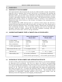
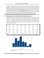
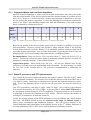
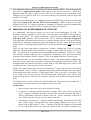
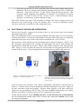
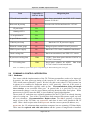
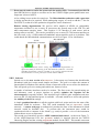
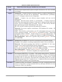
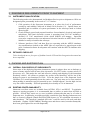
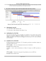
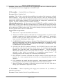
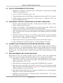
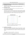
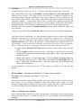
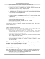
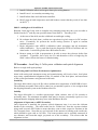
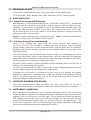
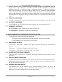
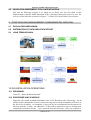
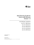
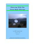
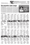
THE SUPERCAM ARRAY AT APEX:
IMPLEMENTATION PLAN
Version 2.2
16 October 2014
Not Export Controlled
Supercam at APEX: Implementation Plan
VERSION HISTORY
Version #
1.1
Implemented
By
Craig Kulesa
Craig Kulesa
Revision
Date
29 July 2014
31 July 2014
1.2
Craig Kulesa
4 Aug 2014
1.3
Craig Kulesa
4 Sept 2014
2.0
2.1
Craig Kulesa
Craig Kulesa
Brian Duffy
Craig Kulesa
12 Oct 2014
15 Oct 2014
1.0
2.2
Approved
By
Approval
Date
Description of Changes
First complete draft
1. Fixed Typos
2. Alignment to subreflector
1. Eliminated staging at
Sequitor. Instrument ships
directly to the summit.
Advanced the schedule to
allow for adequate time for
staging and testing.
2. First round of edits based
on 31 July discussion.
1.
Numerous updates to
laboratory action items.
Updates to deployment plan
Added draft of detailed
schedule for sections 5 & 6
Fixed typo in schedule dates
in Section 6; there were two
24 Nov schedules... the
latter was meant for the 25th.
16 Oct 2014
Page 1 of 33
Supercam at APEX: Implementation Plan
TABLE OF CONTENTS
1 - OVERVIEW..................................................................................................................................4
1.1 - Purpose of This Document...................................................................................................4
1.2 - Current Instrument State & Target Goals for Delivery........................................................4
1.3 - Overview of Development and Integration Efforts..............................................................4
2 - LABORATORY DEVELOPMENT AND INTEGRATION (AUG-OCT)..............................5
2.1 - Improving Yield of Good Pixels in the Focal Plane.............................................................5
2.1.1 - Cryogenic Mixers and Low Noise Amplifiers...........................................................6
2.1.2 - Warm IF processors and FFT Spectrometers.............................................................6
2.2 - Improving Cold Performance of Cryostat............................................................................7
2.3 - Mechanical Mounts: Design and Integration.......................................................................8
2.4 - Optics: Design, TESTING, Integration................................................................................8
2.5 - Electronics: Design and Integration.....................................................................................9
2.6 - Command & Control Integration.......................................................................................10
2.6.1 - Hardware.................................................................................................................10
2.6.2 - Software...................................................................................................................11
2.7 - Data Flow Integration.........................................................................................................12
2.8 - Schedule and Resources Required.....................................................................................12
3 - READINESS REQUIREMENTS PRIOR TO SHIPMENT...................................................14
3.1 - Instrument Qualification.....................................................................................................14
3.2 - Detailed Checklist..............................................................................................................14
4 - PACKING AND SHIPPING PLAN..........................................................................................14
4.1 - Overall Philosophy of Survivability...................................................................................14
4.2 - Existing Crate Availability.................................................................................................14
4.3 - Design and Fabrication for Crates......................................................................................15
4.4 - Packing Plan and Manifest Lists........................................................................................15
4.5 - Shipping Details, Schedule and Responsibilities...............................................................15
5 - ON-SITE STAGING AND TESTING BEFORE INSTALLATION......................................16
5.1 - Personnel on Site................................................................................................................16
5.2 - Overview of Activities........................................................................................................16
5.3 - Schedule of Activities.........................................................................................................16
5.4 - Facility Requirements for Staging......................................................................................19
5.5 - Instrument Checkout Procedure in the APEX Laboratory.................................................19
5.6 - Assembly and Integration State Before Entering C-Cabin.................................................19
5.7 - Risk Assessment and Troubleshooting...............................................................................19
6 - INSTALLATION INTO THE C-CABIN AND EARLY COMMISSIONING......................20
6.1 - Overview of Activities........................................................................................................20
6.2 - Personnel On Site...............................................................................................................20
6.3 - Sun Avoidance Constraints.................................................................................................20
Page 2 of 33
Supercam at APEX: Implementation Plan
6.4 - Schedule of Activities.........................................................................................................20
6.5 - Risk assessment and Troubleshooting................................................................................24
7 - ON-SKY COMMISSIONING TESTS AND QA.....................................................................24
7.1 - Personnel On Site...............................................................................................................25
7.2 - Point and Focus..................................................................................................................25
7.2.1 - Single Pixel through APEX Backend......................................................................25
7.2.2 - Full Array through Supercam Backend...................................................................25
7.3 - Aperture and Beam Efficiencies.........................................................................................25
7.4 - Instrument Calibration........................................................................................................25
7.5 - Position Switching..............................................................................................................26
7.6 - On The Fly Mapping..........................................................................................................26
7.7 - Summary Schedule.............................................................................................................26
8 - MAIN OBSERVING PROGRAM, DATA FLOW, QA...........................................................26
8.1 - Personnel On Site...............................................................................................................26
8.2 - Observing Program Summary............................................................................................26
8.3 - Service Mode Observing....................................................................................................26
8.4 - Scheduling Philosophy.......................................................................................................26
8.5 - Quicklook assessment tools and Mitigation.......................................................................27
9 - POST-RUN DATA MANAGEMENT, DISSEMINATION, ARCHIVAL..............................27
9.1 - Data Access Mechanism.....................................................................................................27
9.2 - Distribution of Data Reduction Effort................................................................................27
9.3 - Long Term Archival...........................................................................................................27
10 - DE-INSTALLATION OPERATIONS....................................................................................27
10.1 - Personnel..........................................................................................................................27
10.2 - Procedure and Schedule...................................................................................................27
Page 3 of 33
Supercam at APEX: Implementation Plan
1
OVERVIEW
1.1
PURPOSE OF THIS DOCUMENT
This Implementation Plan documents the step-by-step efforts needed to prepare and optimize
Supercam prior to shipment from Arizona, and provide a description of the packing and
deployment effort. It is provided as a counterpart to the Supercam-APEX Interface Control
Document (ICD) which provides a direct discussion of the instrument mechanical, electrical,
cryogenic, and software interfaces to the telescope itself. This document provides a broader
approach that includes metrics for instrument readiness, checkout of the instrument at
Sequitor/San Pedro before delivery to the telescope, and staging of the instrument prior to
telescope downtime.
The recognition that APEX telescope time is a precious resource drives the need for a
detailed, thorough implementation plan that all parties are happy with. The ultimate goal is
that the Supercam instrument can be successfully installed, commissioned and productively
used with minimal downtime. This is especially important since the late November and
December observing window typically has observing conditions worsening with time.
Statistically, the best weather will occur during installation!
1.2
CURRENT INSTRUMENT STATE & TARGET GOALS FOR DELIVERY
Parameter
Target Performance
October 2014
# of live mixers
Median Trec(K DSB)
Mixer temperature
52 mixers
100K DSB
5.5 K
60 mixers
<90K DSB
4.5 K
# of IFs, spectrometers
48 of 64
60 of 64
Mean beam efficiency (ηmb)
Sideband ratio
Allan stability time
1.3
Achieved Performance
March 2014
0.7 on Jupiter & Orion
1 +/- 0.2 (1 sigma)
1-8 seconds (continuum)
30-90 seconds (spectroscopic)
0.75
1 +/- 0.2 (>1 sigma)
>10 seconds (continuum)
>120 seconds (spectroscopic)
OVERVIEW OF DEVELOPMENT AND INTEGRATION EFFORTS
In order to achieve the desired level of performance before delivery, two focused campaigns
for Supercam will be performed. The first is to improve the yield of good-performing
devices in the Supercam focal plane (end-to-end; from mixer to spectrometer), and the second
is to improve the thermal performance of the cryogenic system, to drive mixer temperatures
down by 0.5-1K. These two efforts lie at the leading edge of the Supercam implementation
plan during early Fall 2014. A parallel (and following) effort will focus on integration and
testing for the APEX deployment, both in hardware and software. The final effort will be
preparation for deployment, including readiness review, knowledge transfer from the
laboratory team to the deployment team, shipping, and deployment.
Page 4 of 33
Supercam at APEX: Implementation Plan
In order to maximize the likelihood of success with the very minimum of telescope
downtime, a tiered testing and integration plan is proposed. This plan begins with a thorough
laboratory checkout procedure that all deploying personnel will be intimately familiar with
before shipment. This checkout will be repeated to the greatest extent possible when the
instrument is unpacked into the APEX facility laboratory as a prerequisite to proceeding to
installation into the C-cabin. The off-telescope checkout will serve as the final readiness
check and the instrument will be pre-cabled to the greatest extent possible, so that installation
proceeds smoothly and efficiently once the go-ahead for installation has been made.
2 LABORATORY DEVELOPMENT AND INTEGRATION (AUG-OCT)
2.1
IMPROVING YIELD OF GOOD PIXELS IN THE FOCAL PLANE
The March 2014 state of the focal plane was generally in good shape. Table 2.0 below shows
the Y-factor measurements between the ambient load (275K) and a liquid nitrogen load
(eccosorb AN-72) at 80K. A histogram of the 48 pixels with reasonable sensitivity is shown
in Figure 2.1. This performance has been used to characterize the mean integration time
estimates for APEX, but improvement in three areas would benefit the overall instrument
sensitivity. This effort should be the initial focus of the laboratory effort, before moving
onward to APEX integration.
1 2 3 4 5 6 7 8 1 1.61 1.97 2.27 2.25 2.14 0.00 1.89 1.32
2 0.00 2.26 2.27 1.97 2.21 2.19 1.85 0.00
3 0.00 2.20 2.28 1.87 0.00 1.85 2.14 1.87
4 2.30 0.00 2.26 2.14 2.14 1.77 2.05 0.00
5 0.00 2.28 0.00 2.13 2.28 1.19 2.10 2.14
6 2.16 1.99 0.00 2.20 2.26 2.21 1.94 1.81
7 2.26 2.20 2.21 1.32 2.07 0.00 2.13 0.00
8 0.00 2.30 2.16 2.19 1.96 1.93 1.84 1.56
Table 2.0: Typical Y-factors achieved at the HHT. Median Trec in this case is 105 K DSB.
Figure 2.1: Histogram of the noise performance of the nominal 48 pixels
used in Supercam's March 2014 run at the HHT. Median T rec is 105K
DSB in this case.
Page 5 of 33
Supercam at APEX: Implementation Plan
2.1.1 Cryogenic Mixers and Low Noise Amplifiers
Previous focused campaigns to improve the focal plane performance have been successful,
with the current number of live devices greater than 80% and the number of excellent devices
above 50%. However, it is also clear that a further campaign may be beneficial as we have
not yet reached the point of regression. Is there low hanging fruit which can represent the
focus of our effort? One indication might come from the distribution of live and excellent
pixels, separated by 8-beam mixer block.
Mixer
Block #
1
2
3
4
5
6
7
8
# live
5
7
7
8
6
6
6
7
Y > 2.0
4
7
6
8
3
4
4
2
Table 2.1: Number of live pixels and pixels with Y-factors > 2, listed by mixer block.
Based on the number of live devices alone, mixer block #1 would be a candidate for removal
and repopulation. However, special care should be taken with this block as the working
devices in the block are excellent. Blocks 5-7 are uniformly mediocre and none stand out as
especially needing replacement. Row 8 suffers from a lack of good devices, however the LO
pumping of this row or its operating temperature may be a contributing factor.
Recommendation: Swap out devices #2,5,8 on mixer block 1. Swap out devices #3,5 in
block 5. Explore the reason why mixer block #8 uniformly performs poorly even when LO
pumping is seemingly adequate. Is the problem thermal?
August 2014 update: Mixer blocks to be left as-is. We will save Hamdi’s time for any
emergency fixes that need to be implemented at the last minute. The best strategy is to make
the very best of the existing devices. The previous recommendation is maintained for
reference.
2.1.2 Warm IF processors and FFT Spectrometers
Two Caltech IF processors remain problematic and must be repaired. The first is SN7, which
delivers unstable passbands. The second is SN1 which has not been used at the HHT due to
very little IF output. Both must be characterized in the lab and repaired so that they can be
used. Even if we ultimately choose to not use all 8 IF processors, one must be carried as a
spare.
Two FFT spectrometer cards have a single “dead” IF input. One of these is the infamous
Schein board borrowed by the STO-1 flight. A current effort to revive this FFTS board to
use for thermal-vacuum testing for STO-2 is underway. If it passes testing, it can be returned
to Supercam to increase the complement of FFT boards. This will increase the number of
working FFTS channels to 60 from the current 54.
Finally, the current splitting of the FFTS backplanes across the SORAL and Caltech chassis
must end. All SORAL boards need to be returned to the single 3U SORAL chassis to
reduce power consumption and installation footprint. This will involve removal of the
Caltech backplane and reinstallation in the SORAL chassis, as the 2 nd SORAL backplane is
currently installed in STO-2’s XPV and is difficult and time consuming to extract.
Page 6 of 33
Supercam at APEX: Implementation Plan
Two additional issues need to be ironed out with the Omnisys FFTS. One is the perpetual
generation of single-channel spikes which appear to be spurious bit errors. When they
happen to high-order bits, a spike is noted. The level 0 scooper process can flag the worst
offenders, but it would be best if we can isolate and bury this problem, both for Supercam
and STO-2’s benefit.
The final issue which has been a continual problem at the HHT has been the occasional and
aggravating lockup of the internal FFTS control computers. While we hope to solve this
problem in the lab, it is vital to implement a watchdog, or deadman switch to automatically
cycle the AC power to the FFTS in the event that it becomes unresponsive.
2.2
IMPROVING COLD PERFORMANCE OF CRYOSTAT
It is abundantly clear that the mixers are not at the design temperature of 4.5K. The
Sumitomo cold tip, unloaded, is about 3.0K. The load curve of the RDK-415D, indicates a
slope of about 1W/K. The current performance, which shows the mixers at 5.5K and the
cold tip at 4.9K, indicates 1.5W of load at 4K. This is nominally twice the design load.
The significant differential between the two indicates further that the Cold Work Surface
(CWS) has an inadequate conductive path to the Sumitomo cold tip. It also indicates that the
CWS is guilty of carrying the heat load to the cold tip; the thermal load is not at the cold tip
itself.
There are two basic heat paths to characterize: radiative loading and conductive loading.
While the radiation shield at the Sumitomo 2nd stage is indeed 50K, the opposite end is 7580K. The lids may be even hotter due to non-ideal thermal conduction. If they are >100K,
then thermal loading would become a significant contributing factor, and better thermal
strapping of the radiation shield is required. This is a straightforward test of the cryostat.
It is likely that there are also unwanted conductive paths. One known path to consider may
be the DC wiring, which represents a direct (but low cross section) heat path from 300K. We
should heatsink the harnesses carefully to either 50K or 15K (both stages have plenty of lift
capability, but one of the two may be easier to access).
Finally, the copper bracket that connects the Sumitomo 2 nd stage cold tip to the CWS should
be investigated. There is clearly a significant temperature differential that, given the paucity
of functional bolts in the interface, is likely improvable. Does it need to be reworked? N.B.
If one reduces the heat load on the CWS, the temperature differential to the cold tip will
automatically go down. This may be as much a symptom of the problem and not the primary
cause.
The ideal goal is to see the cold tip at 4-4.2K and both the CWS and mixers around 4.5K. I
would define “reasonable success” as seeing the mixers below 5K.
Action items:
1. Open cryostat, remove devices to safe storage for testing.
2. Cooldown #1 (radiation shield temperature testing). Move temp sensors to lids and
recool. Measure Sumitomo load curve with mixers removed: determine 4K load to
achieve performance delivered in March 2014 run. If low, Sumitomo cold head is
sick. If high, then we have an excessive heat leak at 4K.
3. Postmortem to cooldown #1. Calculate radiative heat loading. MLI between 4K CWS
and 15-50K surface (contact Phil Hinz and/or Manny Montoya for access to the
mother lode of MLI on the 4th floor). Calculate UT85-SS-SS conductive load: should
be low and should match coax data and empirical data. If radiative loading not a
Page 7 of 33
Supercam at APEX: Implementation Plan
concern, isolate conductive paths: heatsink DC wires to 15K. Any other thermal
pathways that are bridged when we plug in mixer modules?
4. Implement fixes determined in Step 3 and perform Cooldown #2 sans mixers. (Start
Sumitomo only to compare with cooldown #1 and then add the CTI-350 after initial
testing). If at least 0.5K improvement, clean up all interfaces and reinstall mixers,
warm IV check with cryostat open. When ready to cool, re-perform Sumitomo load
curve and test thermal and RF performance with a full focal plane.
2.3
MECHANICAL MOUNTS: DESIGN AND INTEGRATION
Suggestions: Tasking Ucryo and/or Steward shop with the construction of the cryostat mount
mount, as it will classify as capital. We could include all component purchases for the
extruded aluminum optical subframe, chopper wheel motor, etc. as part of the work effort.
The aluminum subframe and LO mount will be built at the University of Arizona, as we will
have the cryostat. Design needs to be complete by end of August, construction in September,
installation in the lab in October.
Most of the issues involving the mechanical mount are in the corresponding ICD. The basic
action item list is:
1. Complete final detailing in preparation for ordering, machining and welding.
2. Construct the upper octopod structure, down to the secondary mounting ring. Once
tested, ship to APEX as soon as practical so that it can be test-installed on the
telescope.
3. Build U-frame separately and install onto cryostat. Test cryostat mount adjustability.
4. Install calibration load at top of U-mount.
2.4
OPTICS: DESIGN, TESTING, INTEGRATION
At present, the cryostat camera lens is no longer coincident with the dewar window, so the
light path from the beamsplitter to the mixer blocks remains unchanged from the HHT. Thus,
one set of optics need to be constructed for the sky beams. Both sky and LO lenses should
be AR-coated.
The AR-coating prescription, assuming a teflon-to-UHMWPE match, needs to be ¼ wave
(6.9 mil) with an index of refraction that corresponds to 45% pore volume of zitex.
1. Zitex G108 is 8 mil 45% pore volume. This is slightly thick, and moves the band
center to 304 GHz. It will perform OK at 345 GHz (additional 2% loss). This is the
best match possible using stock Zitex.
2. 3-4um pore size G108 is available on Amazon as "fine grade" zitex, part number
D1069175. We have a few small sheets available.
3. Default sheet size is smaller than our lens diameter (but larger than the nominal
radius). One possibility is to match triangular sheets to a given lens (like filling a pie
pan with individual pie slices). This would require experimentation on a sample piece
of HDPE. Alternately, we need to find larger sheets.
4. The master reference for coating HDPE with Zitex is Hargrave & Savini, 2010, Proc
SPIE, 7741 (Cardiff group). They use a vacuum housing to pull the zitex tight.
http://loke.as.arizona.edu/~ckulesa/binaries/supercam/optics/Hargrave_AR_Coat_HDPE.pdf
Page 8 of 33
Supercam at APEX: Implementation Plan
5. We need to use the N135 FTS to verify the losses in lenses and window materials for
calibration. There are already many materials requiring testing for STO-2, HEAT and
Supercam. Action item list here: 1) make FTS go using pyroelectric detector. This
is mostly optical alignment and validation of operation. 2) Accumulate all testing
substrates. 3) Order 30 liters of LHe, 30 liters of LN 2. Confirm bolometer battery
operation, cool bolometer, perform substrate testing.
Team ASU will have the lenses CNC-machined in Tempe. Two weeks (August) needs to be
allocated to the careful design of the lens doublet, and 2-3 weeks for fabrication (Sept),
leaving as much time as possible for AR coating and testing.
2.5
ELECTRONICS: DESIGN AND INTEGRATION
Most of the electronics components will ship as they are, but several issues need attention
regarding integration at APEX.
First, each component needs to be tested and validated with single phase 230V for operation.
All items that cannot or will not be transformed to European power must stay on a dedicated
North American power strip, which will get direct-transformed to 115V at 50 Hz.
The electronics will be deployed in two rackmount racks as shown in Figure 2.2 and 2.3. The
DC electronics will remain in the existing 18U half-height rack; the IF stack includes the
Hammond box, FFTS and IF processor. The IF stack will be mounted on the M3 protection
table. Figure 2.3 does not show the many DC and IF cables crossing between the DC rack,
cryostat, and IF system. Physical passage between them may be possible with some care.
Figure 2.2: Proposed locations of the two "stacks"
of support electronics for Supercam.
Figure 2.3: Baseline plan for installation of
electronics showing DC electronics stack in the
18U rack by the C-cabin door, and IF rack adjacent
to the cryostat.
A list of items in the electronics rack, and its compatibility with APEX is shown below in
Table 2.2. Of these items, the most significant effort and expenditure is the power supply for
the bias electronics cards and preamps. All three linear supplies in the bias card power
supply box are incompatible with 230 VAC. The most straightforward solution is to replace
the three ‘gold bricks’ with their exact 230 VAC counterparts and reinstall.
Finally, the RF interfaces for the 10 MHz reference, and DC interfaces for synchronization
need to identified and suitable (SMA, BNC) coaxial cables fabricated, labeled, and set aside
for testing and shipment.
Page 9 of 33
Supercam at APEX: Implementation Plan
Item
Compatible w/
230VAC 50 Hz
Mitigation plan
CTI cold head controller
No
Run from unswitched non-UPS 115V circuit;
assume 50 Hz ok?
Bias cards & preamp
No
Precede with 2 kW transformer for 115VAC
IF processors
Yes
Omnisys FFTS
Yes
1U acquisition PC
16 port Ethernet switch
Fiducial pixel amp
Yes
Yes
No
Run from 12V IF processor supply
Edwards vacuum gauge
No
Bring out power on BNC from IF processor.
VDI LO power supply
No
Run from 115V circuit; standalone transformer.
No
Run from unswitched, non-UPS 115V circuit
IF processor cooling fans
TBD
12VDC? Run from power brick to 230VAC or
115VAC if necessary.
LO cooling fans
TBD
Need better solution for APEX. Run from
115VAC from LO mini-transformer.
Rack cooling fans
Table 2.2: Summary of electronics power compatibility for APEX and mitigation strategies.
2.6
COMMAND & CONTROL INTEGRATION
2.6.1 Hardware
Two issues with the implementation of the TS-7200 macrocontrollers needs to be improved.
In practice, the slow power-on timing of the Acopian 5V rail sometimes confuses the TS7200, which wants regulated 5V power. We don’t see this on any other TS-7200 systems, but
it appears to be common for Supercam upon a “cold” power-up. Once on, if the power is
cycled, all macrocontrollers typically come up fine. Recommendation: bring out simple
reset switches to an accessible front port. In general this is a good idea in case one
macrocontroller hangs; it can be reset without powering down the entire focal plane. While
unnecessary in 2014’s run at the HHT, it is nevertheless a good risk mitigation.
The no-name CF cards that were originally purchased for the TS-7200’s are already showing
signs of wearing out. Two of the 8 systems have had corrupted filesystems; again, an issue
not seen elsewhere. Recommendation: Replace them. Use dd to generate a reference
image of one of the TS-7200s, say supercam1, and clone it onto 8 new Sandisk 4 GB CF
cards. Write a shell script to turn each supercam1 into the correct system (IP address, etc.).
Supercam9,
the 1U rackmount data acquisition computer, has two spinning 2 TB hard disks.
These must be replaced with solid state drives and the system re-imaged and re-installed.
Page 10 of 33
Supercam at APEX: Implementation Plan
Room must be made to restore the system onto the smaller SSDs. I recommend two 600 GB
Intel SD3500 drives, which we can also use for the GUSSTO flight system qualification once
Supercam is done at APEX.
A few cabling issues need to be sorted out. The Microlambda synthesizer cable connection
is dodgy and needs to be repaired. While undergoing surgery, we need to add the 5 th line for
DATA OUT, so that all of the synthesizer diagnostics can be monitored.
Remote sensing augmentation. We need to add a number of AD590 (or comparable)
temperature monitors to one or more IF processors, the Spacek amp on the VDI LO, and
other temperature-sensitive items. This requires a 12V interface to each sensor, and an
analog return to an ADC. This can be provided by one or more TS-7200 macrocontollers on
the bias cards, or by a USB-connected standalone microcontroller such as an Arduino. This
could absorb the Microlambda communication as well. See Figure 2.2 for clarification.
Figure 2.4: Additional remote sensing information and augmentation of
digital I/O (DIO) for monitoring of the Microlambda synthesizer. The ADC
and DIO functionality could be provided by the existing onboard TS-7200
macrocontrollers or at the point of use with an add-on Arduino.
2.6.2 Software
Switch over to the new version of BiasServer. It has many new features that should make
(Brandon’s) mid-level scripts much simpler and faster. The goal is to reduce the amount of
intermediate Perl/Python code and the volume of network socket server calls to the hardware.
This will speed up receiver tuning and enable new features, below.
A number of software interfaces need to be written. The first set are for general tuning use
and laboratory work. A proper interface to quickly optimize the setpoints for the
electromagnets is urgently needed. This interface logic could be quite straightforward since
access to the I-V data and total power is available. A second would be to assess and optimize
the stability of the LNA settings.
A simple graphical interface to call the requisite mid-level scripts and view the state of the
instrument would be welcome. This GUI could nominally run on supercam9, viewed
remotely. A remote web page to unobtrusively monitor the state of the instrument in North
America would be desirable also. To perform this, the instrument state would be
synchronized with a computer in the North (e.g. soral) to provide a view of the instrument
without direct access to supercam9.
The second set of interfaces involves APEX command and control. As shown in Figure 7.1
of the APEX-Supercam ICD, the apex2hht module is required between the APECS
Observing Engine and the existing SuperComm module for the HHT. This module must turn
Page 11 of 33
Supercam at APEX: Implementation Plan
APECS notifications into the relevant HHT messages and pass them onto SuperComm for
actioning. Testing of this system has as its prerequisite the installation and operation of the
APECS simulator. Both of these tasks are significant efforts.
2.7
DATA FLOW INTEGRATION
The baseline approach to Supercam’s data acquisition, processing, distribution, and archiving
is depicted in the APEX-Supercam ICD in Section 7 and summarized in Figure 7.3. The
augmentations needed to complete this implementation are as follows:
1. The level 0 processing engine scooper will write two parallel data streams. The first
is the nominal SDFITS file, which is written to supercam9’s SSD. The second will be
a new (UDP) streamed raw data interface to the apexOnlineFitsWriter module
running on display2. This stream will consist of 64 x 900 channel structures of 16-bit
data. This will give the standard APEX interfaces access to data from Supercam’s
FFTS and a parallel data interface to the Supercam pipeline.
2. Both SuperComm and scooper need access to basic information about the observation
being performed. This information comes through apex2hht. Section 7 of the ICD
describes the theory of operation.
3. Archiving scripts that will push data from supercam9 to Sequitor are needed.
4. Much more rapid access to processed level 2 maps is needed. One path to this is
already underway using a highly reworked version of CSIRO’s gridzilla package,
which natively speaks SDFITS.
2.8
SCHEDULE AND RESOURCES REQUIRED
Table 2.3 shows the high-level month-by-month schedule of laboratory activities, and Table
2.4 (TBD after initial feedback) itemizes the detailed work efforts with a suggested
responsible person and estimate of the work expenditure in hours.
Page 12 of 33
Supercam at APEX: Implementation Plan
Month
Work efforts listed by type, deadlines by end of month
July
Draft ICD and implementation plan developed, discussed at site visit, reworked
accordingly.
August
Mechanical: Complete design of mounting interface completed including FEA
of critical items and sent out for manufacture. Mini-milestones: preliminary
review 7-29 August, critical review 8 September.
Optical: Complete lens and AR-coat design complete and sent out for
manufacture.
Cryostat: Reworked mixer blocks as recommended. CTI-8200 compressor
leak fixed; unit purged and recharged. Cold tests for radiation shield temps sans
mixers. Fixes for radiation loads as needed. Fixes for CWS cold tip interface
plate performed as needed. Heatsinking for DC wiring.
IF: SN1 and SN7 modules repaired and installed for operation.
Electrical: New power supplies, transformers, UPS purchased for testing. All
cables repaired.
C&C: reset switches, serial consoles, new CF cards bought and sysgen’d. New
remote interfaces enabled. New biasServer and midlevel scripts. Install and
understand APECS simulator. Prepare design for apex2hhtf and interface for
RA/DEC stream for scooper. Prepare test scripts for CORBA/SCPI handling.
Data management: Write level 2 pipeline using rewritten gridzilla. Test with
2014 HHT data.
September
Mechanical and Optical: All interfaces manufactured and assembly begins.
Cryostat: All cryogenic reworking completed this month. Mixers reinstalled.
Electrical: Full system operating from 230VAC or established 115 VAC strip.
All new server racks assembled and tested for deployment.
C&C: apex2hht development and testing with APECS simulator. GUI and midlevel script development. Replace supercam9’s HDDs with SSDs.
Data management: Continue work on gridzilla. Export data via scooper to
apexOnlineFitsWriter. Can this be adequately developed and tested?
October
Development FREEZE by 15 October. Full system testing follows. Readiness
review and documentation of shipping system around 17 October. All deploying
personnel must be able to go into the lab and bring up Supercam to a fully
operating state by themselves! Deconstruction and packing starts 20 October.
Shipping no later than 24-27 October by air. Continued software development
with the APECS simulator after instrument ships.
November
Continued software development. Instrument is en route, and deployment team
arrives 15 November to accept instrument delivery and begin checkout (see next
sections for follow-on schedules).
Table 2.3: Month-by-month coarse breakdown of major laboratory development prior to shipping Supercam.
Page 13 of 33
Supercam at APEX: Implementation Plan
3 READINESS REQUIREMENTS PRIOR TO SHIPMENT
3.1
INSTRUMENT QUALIFICATION
The following needs to be demonstrated via Readiness Review prior to shipment to Chile at a
designated point, presumably in the week of 13-17 October.
1. Cold operation of the Supercam instrument, at or above the level of performance
(sensitivity and stability) achieved in March 2014 (Section 1.2). Optical losses are
quantified and an estimate of system performance at the telescope made to inform
observing PIs.
2. Clearly defined, agreed, and prepared interfaces for mechanical, electrical, and optical
subsystems. Full warm electronics system is operating from 230 VAC including a
declared 115 VAC transformed circuit which SORAL will manage. Supercam
cryocooler compressors have an understood electrical interface at APEX that is either
installed or ready to install at the telescope.
3. Software interfaces (C&C and data flow) are operating with the APECS simulator.
Any modifications needed on the APEX side are expected to be agreed upon at this
point. Continued software development will continue with the APECS simulator after
shipping.
3.2
DETAILED CHECKLIST
To be developed once a first-pass of feedback on the ICD and this Integration document has
been completed.
4 PACKING AND SHIPPING PLAN
4.1
OVERALL PHILOSOPHY OF SURVIVABILITY
Since most of the deploying Supercam instrument system is unique, there are no backups or
spares of many mission-critical items (bias electronics, LO, FFTS cards, cryostat, mixers, IF
processors, etc.). This makes the safe and effective packing and shipping of the instrument
absolutely critical. All efforts to optimize the system in the laboratory will be lost if the
deployed system is not functional in Chile. Even the simple loss of the Supercam Local
Oscillator (LO) would potentially doom the entire run. Not only must we be extra cautious
when packing to maximize survival potential in case “forklift happens”, but the high site has
very low relative humidity – ESD can potentially be as deadly as it is in Antarctica.
4.2
EXISTING CRATE AVAILABILITY
Numerous excellent crates are available from AST/RO, STO-1 and HEAT. To minimize
impact to ongoing programs, it is recommended that we utilize as much from AST/RO as
possible. Several large crates are (or were) available at Sunnyside that may be of value to
Supercam now. In particular, we might especially consider the gray Hardigg rackmount cases
that we formerly shipped (Wanda and PoleSTAR) dewars in, for rackmount electronics or
other hardware. The canonical “standard APL crate” could be used for lab tools and other
incidentals. (Update: BLINC/MIRAC Hardigg cases and dewar crates, located at Sunnyside,
have been green-lighted for use with Supercam).
Page 14 of 33
Supercam at APEX: Implementation Plan
4.3
DESIGN AND FABRICATION FOR CRATES
The following crates are envisioned for shipping. Please edit to suit! We will utilize Phil
Hinz's Hardigg cases to the greatest extent possible.
1. Cryostat crate. Includes most of Supercam mechanical mount.
container. (Dimensions: 1.4 x 1.1 x 1.5 m. Weight: 600 kg)
Large Hardigg
2. Compressor crate #1: CTI-8200 and Sumitomo Indoor unit. (Dimensions: 1.1 x 0.9
x 1 m. Weight: 325 kg)
3. Compressor crate #2: Sumitomo Outdoor unit. Wooden crate. (Dimensions: 1.2 x
0.6 x 1.4 m. Weight: 300 kg)
4. Electronics rack: Contents unloaded and packed into gray Hardigg “WANDA” crate
and empty rackmount chassis disassembled and shipped flat (same crate?). Includes
all DC cables, UPS & coax. (Dimensions: 0.8x 0.8 x 1.4 m. Weight: 350 kg)
5. Transformer crate: 480 → 208 VAC 3-phase compressor transformer. Hardigg case.
(Dimensions: 1.1 x 0.8 x 0.7 m. Weight: 125 kg)
6. M3 table, and extruded aluminum subframe. Hardigg case. (Dimensions: 1.1 x 0.8
x 0.7 m. LO module sold separately. Batteries not included. Weight: 150 kg)
7. Tools and test equipment: Hardigg case. (Dimensions: 1.1 x 0.8 x 0.7 m. Weight:
150 kg)
8. Staging Carts: hydraulic scissor-lift cart and air-ride cart for instrument transfer.
Wooden crate. (Dimensions 1 x 1 x 1.2m Weight:400 kg)
TOTAL VOLUME: XXX m3. TOTAL WEIGHT = 2250 kg.
4.4
PACKING PLAN AND MANIFEST LISTS
This section will be developed once the basic plan for crates has been vetted and adjusted
accordingly.
We will provide Karina Celedon (ESO) with a prospective load plan for the shipment from
Santiago. We will clearly identify/mark the three pieces to be loaded last (first off). We
should have Thomas's concurrence on this.
4.5
SHIPPING DETAILS, SCHEDULE AND RESPONSIBILITIES
I am book-keeping 24-27 October as the shipping period, for a 15 November delivery at the
site. From Carlos de Breuck:
1. The Supercam team will be responsible for providing the adequate packing material
(crates, protections, insulation, etc.).
2. The Supercam team will be responsible that all parts of the instrument will be
properly packed for transport, also for the return shipment from APEX.
3. ESO will coordinate the customs clearance in Santiago. Contact person is Karina
Celedon at ESO Chile.
4. ESO and Sweden will share the shipping costs, both international and within Chile.
This will be initially paid by ESO and reimbursed by Sweden for their part.
5. ESO does not take any responsibility for theft or damage to the crates during the
transport or (un)loading during the entire shipment process.
Page 15 of 33
Supercam at APEX: Implementation Plan
6. While help will be provided by the APEX team, handling of the instrument at APEX
will also remain the responsibility of the Supercam team.
5 ON-SITE STAGING AND TESTING BEFORE INSTALLATION
Figure 5.1: Deployment plan, with personnel color-coded by speciality.
installation, Blue = instrument hardware, Red = instrument software.
5.1
Gray = mechanical and
PERSONNEL ON SITE
15-17 November: Brian, Brandon, Paul
17-22 November: Brian, Brandon, Paul, Ruben, Craig
5.2
OVERVIEW OF ACTIVITIES
The Supercam deployment team will arrive, be introduced to the facility and personnel,
receive the instrument, unpack and setup the instrument in a workspace at the high site,
validate operation of the instrument and stage the instrument prior to the main installation
on 22 November.
5.3
SCHEDULE OF ACTIVITIES
All Supercam activities during the 15-21 November period are to minimize impact on
scheduled APEX activities.
14 November – First wave of deployment team arrives in San Pedro.
Personnel: Brian, Brandon, Paul
Activities: Arrival, initial acclimitization at 2400m. No impact on APEX operations as
stated.
15 November – Deployment team gains first preliminary access to APEX site.
Personnel: Brian, Brandon, Paul
Page 16 of 33
Supercam at APEX: Implementation Plan
Activities: Short initial visit to high site for acclimitization and to re-evaluate the plan for
receiving Supercam, discuss staging space with APEX staff.
16 November – Nominal Delivery of Supercam
Personnel: Brian, Brandon, Paul
Activities: This will be a critical day that establishes the staging of the instrument, available
initial workspace. The goal by the end of the work period is to have all containers safely
stored, with all items that cannot be unloaded without mechanical assistance unloaded and
staged in the APEX entrance module. This would include the compressors, transformer, and
cryostat. All other components can be manually unpacked.
Offloading Requirements: If a box truck is sent, a FORKLIFT capability is required. If a
flatbed truck is sent, a truck CRANE is needed unless it is certain that we can use the facility
crane to offload equipment. One concern is that the horizontal reach of the facility crane may
not be adequate to offload a large truck. The need to interrupt telescope operations is bound
not to be popular either. Advice is needed here.
Suggested flow of operations:
1. Truck arrives. Supercam and APEX staff await it.
2. TOOLS and CARTS containers offloaded first. TOOLS container is opened to make
available components for rigging and staging. CARTS container is unpacked to
liberate air-ride cart, hand truck, and scissor-jack cart. Early availability of these
items eases the offloading of further cargo.
3. COMPRESSOR wooden containers offloaded. The following items must be craned
onto the ground where they can be rigged and hand-trucked, or carted for storage:
INDOOR SUMITOMO UNIT, OUTDOOR SUMITOMO COMPRESSOR, CTI
COMPRESSOR, TRANSFORMER.
4. CRYOSTAT & MOUNT container offloaded. The CRYOSTAT must be craned from
the container and lowered onto the air-ride cart to be transferred to the orange
hydraulic cart at the door jamb of the instrument laboratory. The SECONDARY
MOUNTING RING is then craned and rolled to storage. The crate, then partly
unloaded, is then forked or transferred to its permanent storage location. All
remaining items in this container can be manually offloaded later.
5. ELECTRONICS container offloaded into entrance module. Forklift and slide into
position. Or... crane to ground and use scissor lift cart or big-wheeled dolly to roll to
entryway.
6. If all containers are staged into their respective semi-permanent locations and all
remaining items can then be manually offloaded, the truck can be dismissed.
7. Manual offloading and staging of materials can proceed until the work shift ends or
facility space allocatable to Supercam is filled.
17 November – Manual unpacking and staging into instrument lab (if available) or
appropriate workspace.
Personnel: Brian, Brandon, Paul (Craig and Ruben arrive)
Page 17 of 33
Supercam at APEX: Implementation Plan
Activities: Manual offloading of remaining containers and staging of APEX workspace. The
goal at the end of this day is that the Supercam workspace is configured for operations and
items needed for Supercam initial testing are made available and staged for operations. If
time permits, the Supercam LO subassembly and Supercam electronics rack will be
constructed and populated with items from the Hardigg shipping rack.
Configuration of workspace: Work table and chairs, ethernet and power as per ICD.
Workspace needed to hold cryostat and LO module on cart, Electronics Hardigg container
and Supercam half-height rack, box of Supercam DC cables.
18 November – Continued staging. Instrument setup and testing, day 1.
Personnel: Brian, Brandon, Paul, Craig and Ruben
Activities:
Brian, Paul and Ruben construct the Supercam mount in standalone
configuration. Build the vibration-isolation mounts and the M3 table. Unpack and stage
compressors and transformer and discuss their implementation and interfacing with APEX
staff. Is everything still clear for install?
Brandon and Craig focus on the Supercam electronics rack construction and preparation,
initial testing of the electronics with the Supercam dummy dewar, and if time permits, warm
testing of the cryostat devices (IV curves). (Section 5.5)
19 November – Continued staging. Instrument setup and testing, day 2. By the end of
this day, the warm instrument has been tested (IV curves) and compared to the pre-shipping
warm state.
Personnel: Brian, Brandon, Paul, Craig and Ruben
Activities: Continued from 18 November.
20 November – Instrument setup and testing, day 3.
Personnel: Brian, Brandon, Paul, Craig and Ruben
Activities: Brian, Paul and Ruben: scheduled contingency for the mechanical and electrical
preparation of the Supercam cryostat mount & compressors.
Brandon and Craig build, cable and test the operation and stability of the Supercam IF system
in its rack. At the conclusion of this day, the IF system is notionally ready to be installed.
(Section 5.5)
21 November – Pre-installation review & walkthrough of installation activities.
Personnel: Brian, Brandon, Paul, Craig and Ruben
Activities: Brian, Paul and Ruben: scheduled contingency for the mechanical and electrical
preparation of the mount & compressors.
Brandon and Craig: Scheduled contingency for remaining Supercam instrument preparations
and testing. Cryostat is disconnected and prepared (made safe) for installation. (Section 5.5)
Craig, Per, Carlos: Phase II observation preparations discussed and prepared.
Page 18 of 33
Supercam at APEX: Implementation Plan
5.4
FACILITY REQUIREMENTS FOR STAGING
1. Staging area of footprint ~15 square meters recommended. Larger amount of staging
outdoors for unpacking crates.
2. Access to 230VAC 50 Hz power, up to 10A.
3. Vacuum pumping station with KF flange coupling (Supercam uses KF-50) to cryostat.
4. APEX computer network connectivity, N ethernet ports. IP addresses need to be
known beforehand (see ICD).
5.5
INSTRUMENT CHECKOUT PROCEDURE IN THE APEX LABORATORY
1. Unpack cryostat and install onto stand. Visually inspect and check vacuum. Intact?
Put on vacuum pump if necessary.
2. Install Local Oscillator. Verify multiplier bias voltages and currents. Double-verify
output power with Golay cell or pyroelectric detector if available.
3. Unpack support electronics rack. Reinstall into half-height rack if shipped in Hardigg
crate. Turn on DC bias electronics and computers and validate operation on 8-channel
dummy dewar.
4. When DC electronics check out, very carefully connect cables to cryostat and check
out warm device state. Compute number of live SIS devices, magnets, and LNAs
relative to state of instrument prior to shipping.
5. Install cables for, and verify operation of IF processors and FFT Spectrometer.
6. Prepare IP addresses and software state for C-cabin installation, as needed.
5.6
ASSEMBLY AND INTEGRATION STATE BEFORE ENTERING C-CABIN
Prior to installation, it is envisioned that the cryostat is under rough vacuum and ready to
install as a clean unit. The extruded aluminum subframe will be installed once the cryostat is
mounted in the U-mount. The bias electronics rack is integrated and cabled, as is the IF
processor rack. The cryostat hermetic connections remain “safe” until the instrument is fully
installed.
5.7
RISK ASSESSMENT AND TROUBLESHOOTING
What kinds of issues are possible and how will we respond? This is the brainstorming
section for worst case scenarios and should be added to as we consider the possibilities.
1. Specification of number of live mixers end-to-end (including bias cards, mixers,
LNAs, IF processors, spectrometers) in Sequitor. This defines the go/no-go situation.
What is this number: 16? 32? 48?
2. Ship instrument with metal plate covering window (UHMWPE spare window?)
3. Ship spare bias card and TS-7200 with CF card ready to go for Supercam. Small
flatscreen monitor and USB keyboard for Supercam9. Include null modem cable and
USB-serial adapter to assess from laptop.
4. Ship SORAL helium manifold in case compressor or helium lines are flat or damaged.
Bring spare CTI line, spare Sumitomo line?
5. Nightmare: LO dead on arrival. Emergency ship to VDI and return.
spare Spacek amp from VDI?
Page 19 of 33
Can we get a
Supercam at APEX: Implementation Plan
6 INSTALLATION INTO THE C-CABIN AND EARLY COMMISSIONING
6.1
OVERVIEW OF ACTIVITIES
Starting at the transfer of telescope time, Supercam and its attendant subsystems will be
installed onto the APEX telescope and prepared for commissioning observations.
6.2
PERSONNEL ON SITE
22-26 November: Brian, Brandon, Paul, Ruben, Craig, Jenna (Bill available remotely)
6.3
SUN AVOIDANCE CONSTRAINTS
Note that the C-cabin is not available 24 hours per day. Since the C-cabin stow position
points the antenna at zenith, the telescope must be moved out of this position for a few hours
near local noon (Figure 6.1 below). This implies that the morning shift must never put the
antenna into an unmovable state. Major activities that can lock out the antenna should be
done in the afternoon after Sun avoidance and continue into the evening as needed.
Figure 6.1: Sun avoidance plot for APEX during November 2014. Note
that the 30 degree sun avoidance limit would imply that the antenna needs
to be unstowed and parked safely just after 10 AM local time, and remains
locked out of the C-cabin position until about 2:30 PM.
6.4
SCHEDULE OF ACTIVITIES
There are many parallel activities during installation that may require assistance or oversight
from APEX staff. Depending on how Thomas would like to schedule APEX manpower
resources, we can either split into two shifts to provide around-the-clock coverage, or divide
ourselves into many parallel workstreams on a single shift. Comments on these prospects is
solicited!
22 November – Mechanical Install Day 1: Infrastructure
Personnel: Brian, Brandon, Paul, Ruben, Craig (Jenna arriving?)
Page 20 of 33
Supercam at APEX: Implementation Plan
Activities:
Changeover at local noon (16:30 UTC). Telescope at craning elevation away from Sun.
Paul, Brian Ruben will work on installation of the compressors and transformer with
APEX staff as needed. First stage will be to crane the 3 compressor modules to the
instrument platform and the transformer to the lower compressor level. Compressors and
lines will be transferred first. They will be carted to the crane position and then lofted to the
instrument platform. A hand truck will be used to transfer the compressors through the
instrument room to the opposite side where they will be staged. At this point, items can be
installed into place. Can we turn the compressors on briefly to ensure that they operate?
Brandon will work with APEX to install helium lines, power cables, fiducial IF cable in the
new cable tray.
Craig will work with APEX to install the UPS in the instrument rack and then help Brandon.
Once these items are underway, it is then possible to begin to move towards the C-cabin.
When the telescope can be slewed to zenith (18:30h UTC), access to the C-cabin will be
possible. Once two Supercam team members become free, the first steps to install the
Supercam mount in the C-cabin can take place. The installation steps idealized for the 22 nd
are as follows. At the conclusion of each step, the telescope can still be slewed in elevation.
Hence, each step represents a stopping point for operations which can spill into the 23rd.
1. Install wooden M3 Protection Table and bolt to floor. Can be done by anyone on the
team.
2. Install octopod members onto invar ring – removing one M12 bolt at a time and
installing the Supercam M12 bolts and octopod members in turn. Paul and/or Ruben
should be present.
3. Install cross-member rod and chain hoist. Hoist secondary mounting ring into
position and clamp into place. Mark holes for octopod and match-drill while in
place. Install bolts, washers and nuts. This step requires the core mechanical team
(Brian, Paul and Ruben).
At the conclusion of work efforts on the 22 nd, the telescope can still observe after the team
departs.
23 November – Mechanical Install Day 2: Supercam is installed
Personnel: Brian, Brandon, Paul, Ruben, Craig, Jenna
Activities:
Leftover infrastructure items will have highest priority and then all work will then focus on
the C-cabin. If we are ahead of schedule, we may start solidly in the C-cabin. If so, and
because a limited number of people can work in the C-cabin, today may well be a day where
we divide the Supercam team into shifts and go for ‘around the clock’ coverage.
Shift 1: 2:30 PM local to midnight.
Brian, Paul and Ruben start the first shift, with the aim of installing the Supercam mount and
having the dewar in place. Picking up from the 22 nd, the remainder of the mount must be
installed:
Page 21 of 33
Supercam at APEX: Implementation Plan
1. Install quadrupod vertical support structures into place, minus one.
2. Transfer Supercam cryostat into position if it is not already in position.
•
Cryostat will be staged on the hydraulic cart inside the instrument laboratory and
then rolled to the door. The air-ride cart waits outside.
•
The hydraulic cart is positioned for transfer of cryostat to air-ride cart at the door.
•
The hydraulic cart then runs ahead of the cryostat and is hoisted to the instrument
level in advance of the instrument transfer.
•
Air-ride cart is transferred with cryostat across parking lot to crane transfer area.
•
Cryostat is craned to instrument level where it will be lowered onto the orange
hydraulic cart.
•
The orange cart with cryostat can then be transferred into the C-cabin.
3. Transfer cryostat onto M3 protection table.
4. Hoist cryostat into position and fasten into place with 1/2” bolts.
5. Install fourth vertical support leg.
Now might be a good time to move the telescope and validate the mount. Drive back to
Sequitor and inform shift 2.
Shift 2: midnight to 9:30 AM local
Brandon, Jenna and Craig work to complete any remaining items from shift #1 that are not
too specialized. Then, even if the cryostat is not yet installed, they will:
1. Hoist Electronics rack and IF system onto instrument platform. Roll support
electronics rack(s) into room and bolt to floor and M3 Protection Table, respectively.
2. Verify safety of system under telescope motion.
3. Ensure that DC electronics rack is internally wired and attached to 8 channel “dummy
dewar”, building power, and ethernet.
4. Power on DC electronics rack and validate basic operation on dummy dewar.
5. Zero biases and install all cabling (very carefully) to cryostat if available – IF coaxes
first, then DC cables.
24 November – Install day 3: Final installations, validation, pumpout/cooldown
Personnel: Brian, Brandon, Paul, Ruben, Craig, Jenna
Activities: Again, a double-shift may be the desired mode of operation today.
Shift 1: 2:30 PM local to midnight.
Brian, Paul and Ruben start the first shift, with the aim of a completed Supercam system. If
they have not completed their tasks from the 23rd, they will do so here. And then they will:
1. Bring in the facility vacuum system and pump on the dewar.
2. Install LO module and beamsplitter module.
Page 22 of 33
Supercam at APEX: Implementation Plan
3. Install Calibration wheel and stepper motor plus wiring harness.
4. Install Lens #1 at secondary mounting ring.
5. Install helium lines and cold head controllers.
6. Briefly turn on both compressors and cold heads to ensure that they work (if not done
on the 22nd).
Shift 2: midnight to 9:30 AM local
Brandon, Jenna and Craig work to complete any remaining items they they were not able to
finish from the 23rd and any non-specialist items from Shift #1. Then they will:
1. At the start of the shift, turn the cold heads on and begin cooling.
2. Re-evaluate the focal plane, confirm no regressions in pixel count or in DC monitor
noise. Essentially, we perform the on-site testing (Section 5) again to confirm
nominal operation.
3. Begin integration with APECS (calibration wheel operations and all instrumentrelated callbacks). Try to push data from the Supercam FFTS to FitsWriter and see
what breaks. It would be good to have Bill online for this.
4. Remove pump at 8 AM in preparation to be able to move the telescope before Sun
avoidance. If possible, leave early; the 25 th and thereafter will be a tough slog for
Shift 2 who will bear the brunt of commissioning.
25 November – Install day 4: Cold system validation and optical alignment
Back to a single shift again perhaps.
Cold Testing and Focal Plane Performance Optimization
Initial cold testing and instrument setup and commissioning will involve basic focal plane
array setup, optomechanical alignment of the LO module to the focal plane, and assessment
of the system performance using hot and cold loads.
Sensitivity
The target deliverable is up to 60 IFs with a median noise temperature of 90K DSB or lower.
The minimum acceptable limit will be rather less, presumably equal to or less stringent than
the shipping laboratory state at the Readiness Review.
Stability
The target deliverable is a median spectroscopic Allan variance time of 120 seconds or
preferably more. The minimum acceptable limit may be shorter, presumably equal to or less
stringent than the shipping laboratory state at the Readiness Review.
Alignment of Supercam to APEX Secondary
Once Supercam is installed, the primary optical alignment issue is to steer the 64-beam
bundle to the secondary. The radio beams can be “walked out” from the cryostat window
using small eccosorb HOT loads to ensure that they come to their respective locations at the
f/8 Cassegrain focus. Note that we use hot loads as the antenna is looking at the zenith sky,
which should be quite cold at 345 GHz. The beam positions can be carefully measured at
two distances and from that angle, projected out to the secondary. This assures that the
alignment is close.
Page 23 of 33
Supercam at APEX: Implementation Plan
To adjust the tip and tilt of the instrument, the dewar will be adjusted within its mount.
Note that direct visual inspection of the secondary is not possible from the C-cabin as it is
from the tertiary cabin at the HHT. A Goretex diffuser in the way. Thus, laser alignment onto
the secondary is not practical. Therefore, we must do a very methodical radio beam
alignment within the C-cabin using warm eccosorb loads against the cold sky at zenith.
At the end of initial testing of alignment within the C-cabin, verification at the secondary
should be undertaken if possible using the facility cherry picker. The total power of the
fiducial pixel (through the APEX IF system) and the full array (through Supercam’s IF
system) would be monitored while a (cold) load is waved in a 5-point pattern across the
secondary. The fiducial beam centroid should lie near the center of the secondary, and the
corners of the focal plane array should not spill onto cold sky in any measurable way. At
horizon-pointing, the cold eccosorb load should present a significant contrast to the
atmospheric temperature.
Testing Supercam-APEX Software Interfaces
1. Scooper to apexOnlineFitsWriter. Does data transparently flow into the standard
APEX interfaces? Are calibrations sane? Are data properly archived?
2. Instrument SCPI configurations. Is Supercam recognized as a facility receiver
system? Can observations be prepared and executed with the proper signals being
sent through apex2hht to the relevant Supercam subsystem?
3. Does Supercam’s own pipeline correctly see the telescope configuration and harvest
necessary data to fill its SDFITS headers?
26 November – Install day 5: continuation of items from day 4 as needed.
Otherwise, continue with commissioning (Section 7).
6.5
RISK ASSESSMENT AND TROUBLESHOOTING
This section is difficult to mitigate, but the likely and obvious issues to be worried about are:
1. Unforeseen issues in basic mechanical installation.
2. Difficulty installing mounts and/or cryostat.
3. Difficulty aligning Supercam to the APEX secondary.
4. Issues with transformed power for compressors (e.g. compressors won’t stay on).
5. Software issues in the many APEX and Supercam interfaces (data flow, Supercam pipeline
not getting headers or tracker pointing, SuperComm not following the APEX observing
sequence correctly, data archiving or transfer problems).
7 ON-SKY COMMISSIONING TESTS AND QA
These sections are tersely written in the expectation that they will be completed by the time
of the Readiness Review. At the moment, we have neither experience with the APECS
system nor the typical observing software that is available for instrument checkout to
complete this section. Here, I assume the basic integration that one would assume for any
telescope.
Page 24 of 33
Supercam at APEX: Implementation Plan
7.1
PERSONNEL ON SITE
27 November: Brian, Brandon, Paul, Craig (early), Ruben, Jenna (Bill remote)
28-29 November: Brian, Brandon, Paul, Jenna (Bill remote on 28th, enroute on 29th)
7.2
POINT AND FOCUS
7.2.1 Single Pixel through APEX Backend
Self-explanatory, if the Supercam fiducial pixel is used with a facility FFTS. Pointing and
focus can then be carried out using facility software using the fiducial Supercam beam.
Normally, we use both line and continuum sources for pointing and continuum sources for
focus. We understand that at APEX, it is typical to rely on line sources most. This is OK.
We do need access to at least one planet to assess beam efficiencies, though spectral line
calibrators could be used in a pinch.
Jupiter is available during the run, transiting near dawn. Mars is available in the afternoon
and early evening, with a Sun distance of 45-50 degrees.
7.2.2 Full Array through Supercam Backend
Likely to do pointing and focus using the scooper-exported data interface to
apexOnlineFitsWriter if it is available. Pointing and focus can then be carried out using
facility software using one (or more) Supercam beams, with the others used for validation.
Pointing for all beams is needed to get the per-beam pointing offsets correctly input to the
Supercam pipeline.
One of the first tasks, once the fiducial beam is located on-sky, is to establish the az/el offsets
to all of the other beams, relative to the fiducial beam. This can be done by OTF-mapping a
centroidable source (continuum or spectral line) so that each beam eventually sees the source.
We must quickly process the map to calculate the offsets.
We need to figure out how to get this information into the FitsWriter-derived CLASS files in
addition to the nominal Supercam pipeline.
As a part of commissioning, we need to switch to the A-cabin configuration and determine if
we can reliably return to the same Supercam pointing offsets.
A pointing run will need to be performed over the entire sky to establish the pointing
parameters for Supercam. I presume that we would start with one of the bolometer pointing
models, and that the Supercam team will get the needed help from APEX personnel to
implement changes to that pointing model.
7.3
APERTURE AND BEAM EFFICIENCIES
Total power measurements of Mars and Jupiter, the moon, Orion OMC can be used to
estimate the beam efficiency in comparison to that expected from laboratory expectations.
7.4
INSTRUMENT CALIBRATION
Basic calibration of the intensity scale to antenna temperatures will be done in the usual
manner through the insertion of an ambient-temperature calibration load at regular intervals
(typically every row, or few rows of an OTF map). The per-beam gains will be calculated by
OTF-mapping a spectral line point source with all 64 beams; the same map that will also
generate the azimuth and elevation offsets for all beams relative to the fiducial pixel. The
receiver noise temperature will be evaluated through a hot/cold/sky calibration at infrequent
intervals provided that the instrument configuration is stable.
Page 25 of 33
Supercam at APEX: Implementation Plan
Forward efficiency will be validated using the skydip technique in combination with the
facility water vapor radiometer. Reliable operation of the instrument’s two-position
calibration load will be verified as a part of instrument checkout. If the data is passed to
APEX for processing by apexOnlineFitsWriter and Calibrator, calibration load information
such as temperature must be passed to APECS. Otherwise, Supercam’s internal data pipeline
must get the appropriate hints that the needed calibrations for beam-switching, positionswitching and OTF mapping are being performed so that level 1 processing can automatically
happen.
7.5
POSITION SWITCHING
[List any assumptions for position-switched data for Supercam’s pipeline not already in ICD]
7.6
ON THE FLY MAPPING
[List assumptions for OTF data for Supercam’s pipeline not already shown in ICD]
7.7
SUMMARY SCHEDULE
26-27 November – Basic commissioning, point & focus runs.
27-28 November – Beginning of main observing program.
8 MAIN OBSERVING PROGRAM, DATA FLOW, QA
To complete this section, the Supercam team needs:
8.1
•
Description of all awarded observing time programs and their requirements.
•
Understanding of how the time may be scheduled.
PERSONNEL ON SITE
30 November – 8 December: Brandon, Jenna; Bill, Caleb and Umut arriving. Paul and Brian
leaving.
8 December – 13 December: Brandon, Bill, Caleb, Umut
14 December – 20 December: Brandon, Caleb, Umut, Jorge
8.2
OBSERVING PROGRAM SUMMARY
[Titles and short descriptions of all awarded observing programs and their relative priority
goes here]
8.3
SERVICE MODE OBSERVING
The observations will be performed by the Chilean, ESO and Swedish cognizant observers in
collaboration with the Supercam team (to reduce the data in real time so that assessment of
the data can be done effectively).
8.4
SCHEDULING PHILOSOPHY
The scheduled time will be allocated by the individual partners. What is the role of the
Supercam team in working with the Scheduler and the various PIs to ensure that the
instrument is maximally utilized for best science throughput?
Page 26 of 33
Supercam at APEX: Implementation Plan
8.5
QUICKLOOK ASSESSMENT TOOLS AND MITIGATION
This and all following sections to be filled out in detail once the first draft of this
Implementation, and the APEX-Supercam ICD is discussed and agreed upon. For now, the
overview of the data flow as shown in Figure 7.3 of the ICD is shown below for reference.
9 POST-RUN DATA MANAGEMENT, DISSEMINATION, ARCHIVAL
9.1
DATA ACCESS MECHANISM
9.2
DISTRIBUTION OF DATA REDUCTION EFFORT
9.3
LONG TERM ARCHIVAL
10 DE-INSTALLATION OPERATIONS
10.1 PERSONNEL
Team of 3: Brian, Brandon and Paul?
10.2 PROCEDURE AND SCHEDULE
Supercam will remain installed immediately after its 20 December end of observing. It will
remain in place through the closeout of the observing season and de-installation will occur in
the first week of January. An estimated 2-3 days on site are recommended for the removal of
all items from the C-cabin. An additional 1-2 days will be required to remove all Supercam
components from the telescope. Once removed from the telescope, 2 days are required to
Page 27 of 33
Supercam at APEX: Implementation Plan
pack the instrument. Heavier items such as compressors and cryostat will need to be craned
into their respective containers. A total of 5 days is requested from January 5 to January 10
inclusive.
The de-installation procedure is identically the reverse order of the installation procedure, and
all lessons learned during the actual operation of the former will be used to guide the latter.
The same Supercam team will be involved in the mechanical deinstallation as well.
Page 28 of 33
Supercam at APEX: Implementation Plan
Appendix A: Approval
The undersigned acknowledge they have reviewed this document and agree with
the approach it presents. Changes will be coordinated with ________________
and approved by the undersigned or their designated representatives.
Signature:
Date:
Print Name:
Title:
Role:
Signature:
Date:
Print Name:
Title:
Role:
Signature:
Date:
Print Name:
Title:
Role:
Page 29 of 33
[Insert appropriate disclaimer(s)]
Supercam at APEX: Implementation Plan
APPENDIX B: REFERENCES
[Insert the name, version number, description, and physical location of any
documents referenced in this document. Add rows to the table as necessary.]
The following table summarizes the documents referenced in this document.
Document Name and
Version
APEX-Supercam-ICD
V1.6, 4 Sept 2014
APEX-MPI-MAN-0011
Description
Location
Interface Control Document
for Supercam at APEX
http://loke.as.arizona.edu/~c
kulesa/binaries/supercam/int
egration/APEX/
APECS User Manual
online
APEX SCPI socket
command syntax and
backend data stream format
online
APEX Instruments Generic
CORBA IDL Interfaces
online
APEX Standard Hardware
Interfaces
online
APEX Heterodyne Tertiary
Optics
online
APEX Nasmyth A Cabin
online
MBFITS Raw Data Format
online
V3.0, 21 July 2014
APEX-MPI-ICD-0005
V1.0, 29 March 2006
APEX-MPI-ICD-0004
V1.9, 3 April 2007
APEX-MPI-ICD-0003
V0.5, 6 September 2002
APEX-MPI-DSD-0012
V1.0, 10 January 2006
APEX-MPI-ICD-0001
V1.1, 1 October 2004
APEX-MPI-ICD-0002
V1.63, 5 August 2011
Page 30 of 33
[Insert appropriate disclaimer(s)]
Supercam at APEX: Implementation Plan
APPENDIX C: KEY TERMS
The following table provides definitions for terms relevant to this document.
Term
Definition
C&C
Command and Control
QA
Quality Assurance
UHMW
Ultra high molecular weight
APECS
APEX Control System
FFTS
Fast Fourier Transform Spectrometer
CORBA
Common Object Request Broker Architecture
IDL
Interface Description Language
CDB
Configuration Data Base
SCPI
Standard Commands for Programmable Instrumentation
NTP
Network Time Protocol
Page 31 of 33
[Insert appropriate disclaimer(s)]