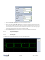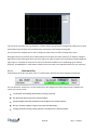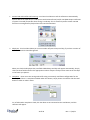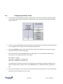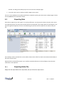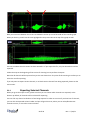
1
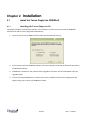
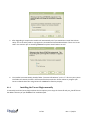
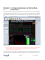
DEWESoft 7.0
Tarsus Plugin
User Manual
Rev. C 2/16/2011
Ulyssix Technologies, Inc
5350 Partners Court, Suite A, Frederick, MD 21703
Tel: 301-846-4800 ~ Fax: 301-846-0686 ~ www.ulyssix.com
Table of Contents
Chapter 1 System Overview ...................................................................................................................................4
1.1
Overview ........................................................................................................................................................4
1.2
Scope of this document .................................................................................................................................4
1.3
What is the Tarsus Plugin? ............................................................................................................................5
Chapter 2 Installation .............................................................................................................................................6
2.1
Install the Tarsus Plugin into DEWESoft? ..................................................................................................6
2.2
Activation of the Tarsus Plugin? ................................................................................................................8
2.3
Locating the Tarsus Plugin .......................................................................................................................11
Chapter 3 Configuring the Hardware ...................................................................................................................13
3.1
Configuring the Bit Sync ..........................................................................................................................13
3.1.1
Bit Sync Input ...................................................................................................................................14
3.1.2
IRIG Time Code Reader ....................................................................................................................15
3.1.3
Bit Sync Outputs ..............................................................................................................................15
3.1.4 Graphical Displays .................................................................................................................................16
3.1.4.1
Eye Diagram .................................................................................................................................16
3.1.4.2
Waveform Diagram .....................................................................................................................17
3.1.4.3
FFT Diagram .................................................................................................................................17
3.1.4.4
Reference Bar ..............................................................................................................................18
3.2
Configuring the Frame Sync.....................................................................................................................19
3.2.1
Configuring the Major Frame ..........................................................................................................21
3.2.2
Configuring the Sub-Frame Sync .....................................................................................................22
3.2.3
Frame Format Identifier ..................................................................................................................23
3.2.4
Configuring Asynchronous embedded PCM Stream .......................................................................24
3.2.5
Frame Lock Criteria ..........................................................................................................................25
3.3
Configuring the Decom ............................................................................................................................25
3.3.1
Parameter Configuration .................................................................................................................27
3.3.2
Importing a parameter list ...............................................................................................................30
3.4
Frame Preview Screen .............................................................................................................................31
3.5
Configuring the Simulator........................................................................................................................33
3.5.1
Configuring Fixed Major Frame Simulator.......................................................................................34
3.5.2
Configuring Archived Playback Simulator ........................................................................................36
3.6
Configuring the LQ Tester ........................................................................................................................36
3.7
Configuring the DAC Outputs ..................................................................................................................37
3.7.1
Configuring Single Bit Output ..........................................................................................................38
3.8
Configuring Math Channels .....................................................................................................................39
3.9
Saving and Loading Setups ......................................................................................................................42
3.9.1
Starting a New Setup .......................................................................................................................42
3.9.2
Loading Previous Setups ..................................................................................................................43
3.9.3
Saving Setup Configuration .............................................................................................................43
Chapter 4 Configuring Display’s & Storing Data ...................................................................................................44
4.1
Creating Displays .....................................................................................................................................44
4.2
Channel List .............................................................................................................................................45
4.3
Using Design Mode ..................................................................................................................................46
2 of 59
Rev. C 2/16/11
4.4
Configuring Display Widget .....................................................................................................................47
4.5
Storing Data .............................................................................................................................................48
4.5.1
Configuring Storing & File Detail ................................................................................................48
4.5.2
Capturing Data ..............................................................................................................................49
Chapter 5 Analysis Mode......................................................................................................................................51
5.1
Replay Data ..............................................................................................................................................51
5.2
Printing Data ............................................................................................................................................53
5.3
Exporting Data .........................................................................................................................................56
5.3.1
Exporting Entire File .....................................................................................................................56
5.3.2
Exporting Section of the File .......................................................................................................57
5.3.3
Exporting Selected Channels ......................................................................................................58
3 of 59
Rev. C 2/16/11
Chapter 1 System Overview
1.1
Overview
The Tarsus Plugin is a software plugin for DEWESoft 7.0 data acquisition software. The Tarsus Plugin requires
that your system has the TarsusHS-PCI-01 card drivers properly installed within it. The combination of the
Tarsus hardware and this TarsusPCM Plugin software provides a powerful complete solution for viewing and
recording PCM data. Let's have a look at the critical components and technologies contained within the
hardware and software.
What is the Tarsus hardware?
The TarsusHS-PCI-01 Processor Board is a multimode PCM Processor board that contains a DSP implemented
digital bit synchronizer, frame synchronizer, IRIG Class II PCM decommutator, PCM simulator and IRIG Time
Code Generator/Reader. The TarsusHS is one of the most flexible and technically advanced PCM Processor
board available. The bit synchronizer accepts all of the IRIG10601 code types and has Eb/N0 rejection of better
than 1 dB to the theoretical BER published curve. The input AGC accepts inputs from 75 mVpp to 10 Vpp.
The Tarsus Plugin allows the user to set up each channel with an easy to use GUI interface, and provides
indicators for bit sync lock, frame lock, subframe lock, as well as soft scope outputs for the AGC data, eye
pattern lock representation as well as a full frame dump display. The output of the frame synchronizer can also
be dumped to the host computer hard drive for archiving and data reduction applications.
The decommutator allows the user to setup parameters from 4 to 64 bits with easy to enter data processing (EU
conversion) algorithms. Asynchronous embedded formats and frame format identifier format changeovers are
supported. All decom processed data may be displayed in tabular, strip chart, oscilloscope, FFT spectral form,
dials, time digital formats, bar graph and other easy to interpret displays.
1.2
Scope of this document
This help file and manual is meant to serve as an adjunct to the current version of the DEWESoft user's manual.
It is not a replacement for that document, which is quite voluminous, and highly detailed, especially in the area
of analog inputs, CAN, GPS, and most standard operational aspects of DEWESoft and Dewetron systems in
general. Please refer to that manual for all general operational aspects of DEWESoft.
This document is intended to supplement that manual with information specific to the TarsusHS-PCI-01
hardware and the software plugin called Tarsus Plugin. Software plugins are specialized applications, usually
created as a DLL, which can "plug in" to the master DEWESoft data acquisition software application, and exist
within that application to add new features and capabilities. Plugins range from very simple applications that
perform a single basic function, or complex plugin such as the Tarsus Plugin, with thousands of features and
functions with extensive interaction with complex hardware.
4 of 59
Rev. C 2/16/11
Plugins are sold separately from DEWESoft, as they have an additional cost associated with them. Of course
they also require hardware (their respective interface cards) to make them run.
Please use this document as a handy reference when using the Tarsus Plugin within your system.
1.3
What is the Tarsus Plugin?
The Tarsus Plugin provides the software interface to the TarsusHS-PCI-01 hardware. It allows you to easily
access and use the bit sync, frame sync, simulator and decom hardware in a graphical, easy to use manner. You
can define parameters for display and recording, create your own screens and save them, and much more.
In this document we will see how to set up and then use the TarsusHS hardware installed within the system, via
the software plugin.
5 of 59
Rev. C 2/16/11
Chapter 2
Installation
2.1
Install the Tarsus Plugin into DEWESoft
2.1.1
Installing the Tarsus Plugin via CD
Installing the plugin is extremely fast and easy. The installation CD from Ulyssix will install the DEWESoft
software suite and the Tarsus plugin files automatically.
1. Insert the CD into the CD-ROM and the installer will automatically start up.
2. If you need to install the DEWESoft software select the Complete Install and the Dewesoft suite will be
installed automatically.
3. If DEWESoft is installed on the machine and an Upgrade to the latest .dll’s and executable select the
Upgrade option.
4. If you have installed DEWESoft in a location other than the default location the message below will
appear asking you to locate your DEWESoft 7 folder.
6 of 59
Rev. C 2/16/11
5. After Upgrading is complete the installer will automatically ask if you would like to install the Tarburn
Utility. This is the utility used to re-program the TarsusHS and TarsusPCM hardware. If there is a Tarsus
card in the machine you are installing DEWESoft on please install Tarburn as well.
6. The installer has automatically placed a folder “TarsusHS .rbf Releases” on the “C” drive on your system. This folder will contain the latest .rbf firmware files that match the .dll files. Please re-program your
Tarsus card with these files using Tarburn for DEWESoft to function properly.
2.1.2
Installing the Tarsus Plugin manually
To manually install the Tarsus plugin without the CD requires you to copy the Tarsus.dll and pcm_hw.dll file into
the addons directory of your DEWESoft 7.0 installation path.
7 of 59
Rev. C 2/16/11
Normally this path is:
c:\DEWESoft7\Bin\V7_0\Addons
But please check your installation to be sure, in the event that it has been installed to an alternate path.
When the DEWESoft application is started, it will automatically scan this directory and register any dlls that it
finds in here. The plugin must still be activated, but it will be registered within Windows automatically.
2.2
Activation of the Tarsus Plugin
After the Tarsus plugin has been properly installed, you must activate it within the DEWESoft application. To do
this, please run DEWESoft. Go to the Settings menu in the top right of the screen and then select Hardware
Setup. When you do this, the Hardware settings dialog box will appear.
8 of 59
Rev. C 2/16/11
(Your settings will be different. This image is just a reference to what the dialog box looks like)
Click on the Plugins button and you will see the list of any plugin DLL and related programs located in the
/addons directory.
DEWESoft automatically attempts to register any plugins that it finds in this directory when it starts. There is no
need to register them additionally with Windows, except in special cases.
If your plugin list is empty, then you have not copied the Tarsus.dll or pcm_hw.dll into the /addon directories.
Otherwise, locate the plugin in the list called Tarsus, and select change the unused to used to activate it:
9 of 59
Rev. C 2/16/11
The PCM Card selector gives you the option to choose from No device, Test mode (replay mode), and Tarsus
PCM card:
1. If you have no Tarsus card at all and wish to see the setup screens for the Tarsus plugin, set this selector
to No device.
2. If you would like to playback and process a .tad file without any hardware, then select the Test mode
(replay mode). When you do this you can select a TAD file that Dewesoft will replay through the
plugin, allowing you to process PCM data without having a Tarsus card installed.
3. If you have a Tarsus card installed and want to process raw PCM data, then choose the TarsusPCM
card selection.
The General settings selector allows you to select several settings to configure the software to your application.
10 of 59
Rev. C 2/16/11
1. Bit Indexing: allows the user to define the order the bits are counted in the Decom. The options are
15..0, 0…15, or 1…16.
2. Word Count: This setting determines where your frame sync pattern falls in your word count. The
options (FS)1…N means the first word after frame sync is word 1 in the minor frame. (FS)3…N describes
the first word in the frame sync pattern as word 1.
3. Use HW Sync for Decoder: Select this if the onboard IRIG Time Code Reader is to be used. Deselect this
setting if computer time is to be used for data time stamping
4. RBF Programming: This will launch Tarsus Flash burn utility for programming the TarsusHS card.
2.3
Locating the Tarsus Plugin
First you need to access the Channel page for the bit synchronizer. There are two options for getting to the
Tarsus channel setup screens. When DEWESoft first opens the SetupFiles tab is opened where all prestored
setups should be located. By double clicking on the New Setup button or a previously created setup DEWESoft
will automatically take you to the Channel Setup tab. If not, hit F2 or just click on the Ch. Setup tab at the top of
the screen.
The setup screen will be shown. By default it will show you the ANALOG tab, which consists of any analog inputs
that your system may have.
Note the tabbed interface which shows whatever interfaces are installed in your system. In the case of the
screen below, they are Analog, Math, and Tarsus :
11 of 59
Rev. C 2/16/11
Depending on Your Hardware Settings your system may be different. For example, it could look like this:
Note all of the additional tabs on this screen: Analog, Video,Alarms, Tarsus Plugins, Torsional Vibration ....
there are even more possibilities. The point is that these tabs will reflect exactly those hardware and software
options which your system has installed.
12 of 59
Rev. C 2/16/11
Chapter 3 Configuring the Hardware
3.1
Configuring the Bit Sync
Go to the Ch. setup screen either by clicking the Ch. setup tab in the top tool bar or by pressing F2 on your
keyboard. The setup screen will be shown. Click the Tarsus tab and then press the Bit sync button.
On this screen you set up the frontend of the system including selecting the input, code type, bit rate, loop
bandwidth and more. The classic "eye diagram" is shown prominently as a reference along with direct view of
your incoming data and FFT (frequency spectrum) views of the incoming PCM signal.
If there are multiple cards inside a single system they will run and are setup independent of each other. Each
card can be selected by the drop down menu shown below:
13 of 59
Rev. C 2/16/11
3.1.1
Bit Sync Input
1. Input:
Here you can select from between the two inputs of the TarsusHS card
2. Code type:
Select the appropriate code type for the incoming PCM stream.
Codes supported by the hardware include: NRZL, NRZM, NRZS, Bi*L, Bi*M, Bi*S, DMM, DMS, RZ, RNRZ(11)Forward, RNRZ(11)Reverse, RNRZ(15)Forward, RNRZ(15)Reverse
14 of 59
Rev. C 2/16/11
3. Bit rate:
Enter the bit rate of the incoming PCM stream. The TarsusHS-PCI-01 can handle bit rates up to 33 Mbps.
4. Polarity:
Select Normal, Inverted or Automatic polarity (detection).
5. Loop bandwidth:
Setting in the range of .01 to 3.00 percent. Using a smaller Loop BW setting will achieve better bit error
performance out of the Bit Sync, however if the input PCM data rate is slightly low or high a lock may
not occur
3.1.2
IRIG Time Code Reader
Time code type:
Here you can select from among the IRIG input types and sources:
The selection of Computer indicates that there is no time code entered directly into the TarsusHS card, but that
the time code present on the computer system is being used as the time reference. This can only be done if
there is only a single TarsusHS card in the system (no other hardware running under DEWESoft)
3.1.3
Bit Sync Outputs
1. Select the PCM code type for the first output of the Bit Sync. The output code types are; non-return to
zero level (NRZ_L), non-return to zero mark (NRZ_M), non-return to zero space (NRZ_S), bi-phase level
(BI _L), bi-phase mark (BI _M), bi-phase space (BI _S), delay modulation mark (DM_M), delay
modulation space (DM_S), return to zero (RZ), randomized non-return to zero RNRZ_11 and RNRZ_15
and are completely independent from the input type.
15 of 59
Rev. C 2/16/11
2. Select either Normal or Inverted polarity for the output PCM data stream.
3. Select a clock phase of 0, 90, 180 or 270 degrees. This setting will change the relationship of the data
with respect to the PCM clock rising edge. The proper setting here will depend entirely on the type of
external equipment being attached. To setup a second Bit Sync output for the same input signal, go to
step 10, other wise press OK to save or Cancel to abandon changes.
4. Select Use External Input if the second output is to be used as a standalone code converter.
3.1.4
Graphical Displays
3.1.4.1
Eye Diagram
This display shows the incoming PCM stream in the classic "eye diagram" graph.
16 of 59
Rev. C 2/16/11
Using the Persistence selector, you can set how many plots are kept on the screen at once. The default setting is
25 and generally provides the best visual reference. You can increase the persistence to 50 or 100, but this takes
more computer memory and also takes longer to update the display. the recommended setting for most
applications is 25.
Use the Pause button to temporarily freeze the eye diagram for visual study. Press this button again to resume
the display updates.
3.1.4.2
Waveform Diagram
This display shows the incoming PCM stream in a conventional Y/T (amplitude versus time, i.e., oscilloscope
type) graph, where the amplitude is shown in percentage, and time is shown in milliseconds (ms):
You can hover the mouse over the waveform and the display will calculate the amplitude (vertical Y axis), the
time (horizontal X axis) and show them numerically at the bottom of the graph.
3.1.4.3
FFT Diagram
This display shows the incoming PCM stream in a FFT (magnitude versus frequency, i.e., FFT/spectal) graph,
where the magnitude is shown in decibels (dB), and the frequency is shown in Hertz (Hz, kHz, or MHz)
17 of 59
Rev. C 2/16/11
You can hover the mouse over the waveform and the display will calculate the magnitude in dB (vertical Y axis)
and frequency (horizontal X axis) and show them numerically at the bottom of the graph.
You may select the window type for the FFT display and the zoom level from the drop down menu.
Rectangular does not influence the FFT decomposition at all, while the other selections are industry standard
algorithms used for biasing the lobes of the FFT analysis in order to improve the calculations based on different
signal types. It is beyond the scope of this manual to describe the different FFT windowing types and their
purposes. The DEWESoft 6.x manual does include such an overview in the appendix section for your reference.
3.1.4.4
Reference Bar
At the bottom of the bit sync setup screen is a reference bar which shows some important parameters:
The core elements, shown here, are also shown when you change to the other setup screens related to the
Tarsus card. These include:
Info ON/OFF this indicates which stream is being monitored
Bit rate shows the bit rate for the selected stream
Signal strength shows the strength as a percentage for the selected stream
Bit sync shows the status of signal lock on the selected stream.
Polarity shows the current polarity (Normal or Inverted) for the selected stream
18 of 59
Rev. C 2/16/11
The headers of the parameters called Bit rate, Sig strength, Bit sync, and Polarity are actually buttons that can
be pressed in.
Any of these parameters whose header button is pressed in will become available channels in the Dewesoft
display screens under the status folder of each card. This allows you to display it on the screen in a digital
meter, status display, tabular display, recorder window or in any of the graphical display widgets available
within the software.
3.2
Configuring the Frame Sync
Go to the Ch. setup screen either by clicking the Ch. setup tab in the top tool bar or by pressing F2 on your
keyboard. The setup screen will be shown. Click the Tarsus tab then press the Frame sync button.
On this screen you define the framing of the data within the PCM stream including the data length, frame
format identifier and any asynchronous embedded streams that may be present within the data. Other
important settings include the frame lock criteria of the major and minor frames.
19 of 59
Rev. C 2/16/11
1. Stream TAD and C10 files while storing – use these check boxes to tell the software to automatically
archive data to the hard drive in a TAD (Tarsus Archive Data format) and/or C10 (IRIG Chapter 10 format
if system is licensed) format file when storing is underway. This is commonly used to create raw TAD
files from incoming data for playback out of the Archive Simulator.
2. Skip bytes - this check box allows you to set a number of bytes to keep and skip, if you have a section of
the PCM data which should be ignored.
When you check the Skip bytes box, two fields labeled Keep and Skip will appear automatically. Simply
click into these fields and enter the appropriate number of bytes. The byte count starts at the first byte
in the frame sync pattern.
3. Templates - these are a time saving method of saving a commonly used frame configuration for the
frame sync. If there is a template available under the selector, simply choose it and then click the Load
button in order to make it active.
Or, to find another template to load, click the down arrow connected to the Load button, and this
submenu will appear.
20 of 59
Rev. C 2/16/11
3.2.1
Configuring the Major Frame
1. In this section you need to define the total number of bits in the frame sync pattern from 16 to 33 bits.
In the example below we have entered 32. To change this value, simply click into the field and edit the
value shown here.
2. If you are using the IRIG Standard frame sync patterns the hexadecimal value will be automatically filled
in. To change this value, simply click into the field and edit the value.
3. Select the Use Mask to setup a mask value that will cause the TarsusHS frame sync circuitry to ignore
certain bits of the sync word. If using mask:
Enter a mask value using the following logic rules: logic high or ‘1’ in any bit position will cause the Frame Sync circuitry to ignore that bit. For example:
Sync word size : 32 bits
Sync pattern : FE6B2840 ( in Hexadecimal)
Mask value : 0000F000 ( in Hexadecimal)
This example will cause the Frame Sync circuit to ignore bits 12 through 15 during sync detection. Any
value in the PCM stream where the “2” in the FE6B2840 pattern is located would cause a valid frame
lock.
4. Now enter the number of minor frames per major frame (we have entered 63 in the screen shot above).
Simply click in the field and enter your number.
21 of 59
Rev. C 2/16/11
5. Now enter the Last word number in the minor frame (we have entered 160 in the screen shot below).
Simply click in the field and enter your number. Also enter the number of Bits per word by clicking in the
field and typing the correct value. We have entered 16 in the screen below. This setting is dependent of
the Word Count setting under the Hardware Setup.
3.2.2
Configuring the Sub-Frame Sync
To configure the Sub-Frame Sync, follow the step by step procedure below.
1. Select the Sub-Frame synchronization method the TarsusPCM hardware should use. Select either SubFrame ID counter (SFID), Frame Code Complement (FCC) or No minor frame sync (None). If SFID is
selected, go to step 2, otherwise skip ahead to the next section.
2. Setup the SFID by entering the number of the word location in the frame of the SFID word. For example
if you have a 32 bit frame sync pattern with 16 bit words and the SFID is the first word after sync then
the start word is 3
3. Then enter the start bit in the SFID word and the total number of bits.
4. Next, select the word order, up or down, using the toggle button. If it says Up, clicking it will change the
direction to Down, and vice versa. Notice that the numbers will flip around to match your selection. In
the screen shot above, we have selected Up, and therefore the numbers count up from 0 to 99. If we
select Down , the numbers flip around to count down from 99 to 0:
22 of 59
Rev. C 2/16/11
3.2.3
Frame Format Identifier
A Frame Format Identifier (FFI) word is used to allow the decom hardware to identify a unique pattern in the
PCM stream and perform a format switch.
If your data stream has one or more frame format identifiers (FFI's), you need to check this box and then enter
the integer value corresponding to the word location in the frame, and then enter the word length in bits,
appropriate to your data:
When you put a checkmark in the FFI box, you will be prompted to enter the integer value of the FFI:
1. We have entered 129 into the dialog box, and then clicked OK to set this FFI value.
2. Enter the minor frame in which the FFI starts in the Start frame. For this example it starts in the first
minor so we enter 0.
3. Enter the Interval on how many minor frames must go by before we see the FFI again. In this example
we have a 1 so it will be every minor frame. If we placed a 100 for the interval we would see the FFI
every 100th minor frame.
4. To add another FFI, use the Add button to create one. The same dialog box will appear allowing you to
enter the value. As soon as more than one FFI exist,you can use the selector to choose among them,
and edit their properties.
23 of 59
Rev. C 2/16/11
3.2.4
Configuring Asynchronous embedded PCM Stream
If your PCM stream contains one or more asynchronous PCM streams, use the ADD ASYNC button to add each
one and then define it.
When you add an asynchronous stream, you must define where it is in the top level PCM stream. Enter the
starting word and end word by clicking into the fields below.
Use the ADD ASYNC button to add another asynchronous stream or the DEL ASYNC button to delete the
selected one. With these controls you may add and manage multiple asynchronous streams.
Dewesoft can process multiple asynchronous PCM streams at the same time. To setup each asynchronous PCM
frame format use the drop down menu below to select between the different streams.
24 of 59
Rev. C 2/16/11
3.2.5
Frame Lock Criteria
1. Frame Lock Criteria, i.e., the allowed transitions the hardware requires before changing the frame
status from search > check, and then from check > lock. Then the allowed transitions the hardware
requires before changing the frame status from lock > check, and check > search. These must be
integers representing a number of frames, and normally low values are used of one or greater.
2. Sync window (bits) or also known as bit slips are the number of allowed bit errors in your total number
of bits per minor frame.
3. Allowed sync error (bits) are the number of bit errors allowed in the frame sync pattern to remain
locked to the data
4. Use the Data In Search Mode selection if the user desires data regardless of Frame Lock.
5. Use the Burst Mode selection if the user is expecting a limited number of minor frames.
6.
3.3
Minor Frame Lock Criteria, i.e., the allowed transitions the hardware requires before changing the
minor frame status from search > check, and then from check > lock. Then enter the number of allowed
transitions the hardware requires before changing the frame status from lock > check, and check >
search. These must be integers representing a number of frames, and normally low values are used of
one or greater.
Configuring the Decom
Go to the Ch. setup screen either by clicking the Ch. setup tab in the top tool bar, or by pressing F2 on your
keyboard. The setup screen will be shown. Click the Tarsus tab, then press the Decom button.
25 of 59
Rev. C 2/16/11
On this screen you will set up the system to decommutate the PCM stream. It sets up the software extract
individual parameter data from the PCM stream. The extracted data will be identified, combined and processed
which will then allow the user to visualize and analyze the PCM data.
Notice the selector which presently says "Main stream" in the image above. You may use this to select your
asynchronous stream (if defined in the Frame Sync Setup), and the channels from that stream will be shown on
the main display. Click the selector and then choose the desired stream to define parameters.
1. The Add/Remove buttons are to add or remove a new parameter to the decom setup.
2. The Copy/Paste buttons utilize the Windows clip board to copy selected (the marked or darkened index
number) parameters to the clip board. The user can then paste these same parameters to other cards
within the same system.
3. The Import button is for importing DEWESoft registered parameter lists for easy loading of parameter
setups. Definition of a .txt parameter import file is located at the end of the document.
4. Parameter table heading definitions
Index - is the number from 0 to n (the total number of channels plus one) of the parameter
On/Off - the used/unused status of the scaled output from this channel (when set to "Used", it can be
displayed and recorded)
26 of 59
Rev. C 2/16/11
On/Off Raw - the used/unused status of the raw (unscaled) output from this channel (when set to
"Used", it can be displayed and recorded)
C - (color) the color of this channel. It can be set here by clicking the color icon or on the Channel Setup
screen
Name - is the name of this channel. It can be set here or on the Channel Setup screen
Word - is the word number in the minor frame of this channel
Start frame – is the start frame of this channel, will be a number unless the channel is set to "Normal
comm" instead of subcom or supercom
Rate - is the update rate in minor frames of this channel
Size – is the bit length of this channel
Values – are a preview of this channel, scaled against the min/max values
3.3.1
Parameter Configuration
This is one of the most important aspects of the system because it is where you define the Parameters, or
"Channels" which are to be extracted and made available for display and recording within the software.
Note - you can turn on or off the raw and scaled output values from each parameter independently. Simply click
on the Unused button in the same row as the desired parameter to change it to Used, and vice versa.
1. Press the Add button to open a new channel setup window or modify an existing channel by pressing
the Setup button at the end of each parameter's row.
27 of 59
Rev. C 2/16/11
2. Channel Info: here is where you can set up the top level properties of this channel.
Name - enter a name for this channel
Description - (optional) enter additional info about this channel
Units - enter the engineering units for this channel (V, A, degrees, PSI, etc.)
Color - click this windows widget to set the color for this channel.
Delay - enter the number of milliseconds that this channel is delayed by, so that the software can
offset it
Min value - set the display scale for this channel: low side
Max value - set the display scale for this channel: high side
Note - the min and max values have no effect on the data being recorded. These fields only set the default
display scaling.
3. Decoding and Scaling: here you set up how this channel is interpreted by the software.
Date Type - This is how the data word extracted from the PCM stream is represented in memory. When
Two’s Comp or One’s Comp is selected, the data will be represented as positive and negative values.
These values will be sign extended when extracted from the PCM stream. The Binary selection will treat
data as positive binary values with no sign extension.
28 of 59
Rev. C 2/16/11
Data format select from between big endian and little endian.
Scaling values (A0, A1, A2, A3, A4, A5) you can enter the scaling values according to the formula
shown below the fields, where: A0 + A1 * x + A2 * x + x + A3 * x * x * x ... Enter as many scaling
factor values as you need for this channel; leave the others with the default zeroes in them.
4. PCM Frame Location: you can set the commutation type and bit locations for this channel.
Commutation Type – Select from Normal, SuperComm, or SubComm for parameter type
Interval – Used for your SuperComm or SubComm words. For SuperComm words this is the word
interval in between the samples. For SubComm this is the minor frame interval in between samples
Bit mapping table - here you define:
o Start frame – Is the minor frame number the parameter data starts
o Start word – Is the word number in the minor frame the parameter data starts
o Start bit – Is the start bit in the word where the parameter data starts
o Length - (in bits) of the number of bits in the parameter data
Bit Concatenation - where you need to combine bits from different parts of the frame to make one
parameter. Ex imbedded Time.
29 of 59
Rev. C 2/16/11
o
o
o
Use the [+] and [-] buttons to add indices to the bitmapping table.
Then you can click within each value in the newly created row
You can also select any index number and then use the [] button to delete it.
5. Values Preview – A very useful tool to look at the values preview at the bottom of the dialog to see the
effect of your scaling against the real data. Also gives overall view of parameter as you concatenate bits
together to build a parameter.
Use raw and scaled values, these check boxes serve exactly the same function as the Used/Unused buttons for
the raw and scaled outputs from this channel, back on the Decom setup screen. You can also set them here
using these check boxes.
3.3.2
Importing a parameter list
You may import a list of parameters which has already been defined in a flat text file format. Click the Import
button as shown here on the decom setup screen:
And you will be presented with the Open dialog box, where you can navigate your computer and locate the txt
30 of 59
Rev. C 2/16/11
file that you would like to load:
If you have channels (parameters) defined already on the decom setup screen, you can control what the
software will do when you load a template which contains channels which may overwrite those existing ones.
The choices are to:
Delete previous channels , conflicting channels from the template will be imported. Existing channels
will be deleted.
Keep previous channels, conflicting channels from the template will not be imported. Existing channels
will not be deleted.
Select the desired template and then click the Open button. When you do so, the list will be imported instantly.
There is a reference info page at the end of this document which gives the exact format of this file.
3.4
Frame Preview Screen
Go to the Ch. setup screen either by clicking the Ch. setup tab in the top tool bar, or by pressing F2 on your
keyboard. The setup screen will be shown. Click the Tarsus tab, and then press the Frame preview button.
31 of 59
Rev. C 2/16/11
The frame preview screen gives you a clean look at the raw live frame dump of the major frame data in
hexadecmial. The first minor frame with the minor frame time stamp starts at the top. The channel color labels
show your Normal, SuperComm, and SubComm parameter locations in the major frame.
The P next to the time stamp will pause the screen in time.
32 of 59
Rev. C 2/16/11
By clicking on a word in the major frame a window will appear giving detailed information on that individual
word.
If that word is not defined as a parameter select: Add New Channel. This will automatically bring up the decom
channel setup screen with the correct frame location information filled in.
3.5
Configuring the Simulator
Go to the Ch. setup screen either by clicking the Ch. setup tab in the top tool bar, or by pressing F2 on your
keyboard. The setup screen will be shown. Click the Tarsus tab, and then press the Simulator button.
1. First enable the simulator using the check box to have the data start coming out the Simout BNC
2. Select between the Simulated data simulator and the Archived data playback simulator.
3. Make sure to press Apply to load your setting changes before saving or changing screens. If you do not
hit Apply before you changes screens all your work will be lost. This goes for everything under the
simulator tab.
4. Bit Sync Settings
Select the Code type for the simulator output
Select the Bit rate for the simulator output from 1 bps to 33 Mbps
33 of 59
Rev. C 2/16/11
3.5.1
Configuring Fixed Major Frame Simulator
1. Simulator Type: select Simulated
2.
Frame Settings – this is where we define the specifications of our major frame
Minor frames – enter the number of minor frames per major frame
Last word – enter the number of the last word (total number of words including sync in word
count) per minor frame
Bits/Word – Enter the number of bits per word
Sync Bits – Enter the number for bits in your frame sync pattern
Sync Pattern – if using the IRIG standard patterns it will automatically fill in according to your
number of Sync Bits or a custom pattern can be entered.
5. Subframe Settings – this is where we define the type of sub frame counting we would like
Sync type – Select between SFID or FCC (Frame Code Complement)
Start Word – enter where in your frame you would like the SFID
Start SFID – Enter the start value for the SFID and select either counting up or down.
6. FEC (Forward Error Correction) is only available with the TarsusHS-PCI-01.
7. Channel Settings : Configuring individual channels or parameters in the Major Frame
Hit the + button to add a new channel and the – button to delete unwanted channels.
Default Value (Hex) – Enter the Hexadecimal value that will be filled into undefined words
34 of 59
Rev. C 2/16/11
Edit Simulator Channel:
Name – Select an identifying name for the given channel
Start Frame – The number of the first minor frame this parameter should start in
Start Word – The start word in that minor frame for that parameter
Commutation type - Select if the parameter is to be Normal, SubComm, or SuperComm
channel. Then type and the interval for the Super or Sub comm. Channel
Data – Two types: Fixed value in Hexadecimal or Function. Function will automatically
do the math to give the selected waveform the entered Points/Period.
35 of 59
Rev. C 2/16/11
3.5.2
Configuring Archived Playback Simulator
1. Simulator Type: select Archived
2. Archived Data
Archive File - Locate on the Hard drive the .tad file that is to be replayed
Continuous Loop Mode – replace the file on a continuous loop from start to finish and
automatically restart the file.
Start Position – Use the arrow to select where in the file using the time tag to start playing the
file
End Position – Use the arrow to select where in the file using the time tag to stop to playing the
file
3.6
Configuring the LQTester
Go to the Ch. setup screen either by clicking the Ch. setup tab in the top tool bar, or by pressing F2 on your
keyboard. The setup screen will be shown. Click the Tarsus tab, and then press the LQ Tester button. This option
is only available for TarsusHS-PCI-01 users only.
36 of 59
Rev. C 2/16/11
The LQTester section performs a bit error tester (BERT) function using the internally setup simulator
format.
The LQTester Setup form allows the user the ability to setup both the transmit function as well as the
receive function for the quality (BERT) functions.
1. Transmission section, the user selects the transmission bit rate and code type for the PCM data to be
output from the LQTester. The data is output using the SIMOUT output on the Tarsus pigtail connector.
2. Receiving section, the user selects the sampling interval for the BERT function. This interval allows the
user to select the resolution and accuracy that is desired for the bit rate and data type selected. The
larger the interval, the more the number of samples that are measured, the longer the time between
measurements occurs. The sampling interval is selectable for intervals from 2^8 to 2^32 with 2^4
spacing.
3. The user then selects if the internal bit sync is used for receiving data CH1IN BNC on the TarsusPCM
pigtail.
4. Bit Error Rate Test section, the user can conduct BERT test and insert errors to check the bit sync and
get BER real time.
3.7
Configuring the DAC Outputs
Go to the Ch. setup screen either by clicking the Ch. setup tab in the top tool bar, or by pressing F2 on your
keyboard. The setup screen will be shown. Click the Tarsus tab, and then press the DAC Output button.
37 of 59
Rev. C 2/16/11
1. Enable the Decom DAC output by clicking on the Enabled box.
2. Enter the word in the PCM frame to extract for sending to the DAC.
3. Select SuperComm, SubComm or Normal for the type of data to extract.
4. Enter the interval in words if SuperComm or frames if SubComm for the data to be sampled and
sent to the DAC.
5. Select from 1 to 10 Volts Peak to Peak for the analog output level.
6. Select from -5 to 5 Volts DC for the analog output offset.
7. If using two DAC outputs, repeat steps 1 through 6 for DAC2 outputs.
3.7.1
Configuring Single Bit Output
Each of the on board DACs allows for the output of a single selected bit. Of the most significant 12 bits of a
word, the user can select 1 bit to be output via the DAC. For example:
If there is a 16 bit word (calling bit 0 the LSB), only bits 3 – 15 would be available for selection.
However, in the DAC form, the bits will be listed as 0-12 no matter what the word size. In this scenario bit 3 of
the word would correspond to bit 0 on the DAC output form.
38 of 59
Rev. C 2/16/11
To use the single bit output feature:
1. Open the Decom Outputs Form (instructions in previous section).
2. In the Bit Selection section, check the box to enable bit selection.
3. Select whether to invert the output or not.
4. Select any one of the bit checkboxes corresponding to the desired bit for output. EX. I wish to output bit
1 (LSB=0) of a 10 bit word. I select bit 3 of this section because the word is being MSB aligned with bit
11 on this form.
5. For bit selection, the word is MSB aligned with bit 11 on this form. If the MSB of the word is
bit 9, that would correspond to bit 11 on this form. In other words, the MSB of the word is
ALWAYS in bit 11 of this form.
3.8
Configuring Math Channels
Go to the Ch. setup screen either by clicking the Ch. setup tab in the top tool bar, or by pressing F2 on your
keyboard. The setup screen will be shown. Click the Math tab.
Math channels are DEWESoft functions included in all versions. This powerful feature allows you to combine
channels from different sources and create new parameters which are the result of all kinds of calculations.
Please refer to the DEWESoft manual to learn more about Math channels and to see a comprehensive list of
capabilities. In this manual we will show just a few basics about this functionality in order to illustrate the basic
capabilities of the DEWESoft Math function.
To create a new formula channel, click the first Math tab button, marked in the screen shot below. When you
do so, a new formula channel will appear at the bottom of the channel row. (Math channels are appended to
the list if this is the first channel created, it will be at the top, and all subsequent channels will be
appended below in the order in which they are created)
39 of 59
Rev. C 2/16/11
To edit this channel, click the Setup button at the right of its row, and the formula editor will pop up:
Name/Description/Units/Color - freely editable variables
Formula line - the most important element this is where you create your actual formula
Preview bar graph - Even during editing you can see the results of the formula expressed here in this
scalable graph
40 of 59
Rev. C 2/16/11
Arithmetic operators - the basic math elements are here for inclusion in your formula
Other math functions - including measurement, trigonometry, logic/boolean, algebraic, and
more
The channel list - sortable via tabs, to select the types and sources of channels
Notice in the screen image above we have entered a formula already:
‘Main stream/SFID’ + 'Counter’
Note that each channel must be given with single quotes around it. The easiest way to ensure that the channel
name is entered properly is to place the cursor at the point within the formula line that you want the channel
name to appear, and then double click the name within the channel list. That will place the selected channel in
the formula perfectly.
You may type operators directly into your formula line, or click the icon from the operator section and functions
tabs. It doesn't matter how you do it, as long as the operator is properly formatted, and in the correct place.
41 of 59
Rev. C 2/16/11
Some functions have specific syntax requirements, like the calculation of absolute value, for example. You can
hover the mouse over most functions and a short balloon help will pop up to give you a reminder about how to
use it.
3.9
Saving and Loading Setups
Dewesoft makes it easy to save and load any hardware configuration. The setups can be stored to the local hard
drive to be used by the unit or transferred to other measurement units.
In Dewesoft, a "Setup" contains all of the settings which are active at the moment you save it, except for the
few global parameters which are restored automatically when the software is started. Global parameters are
those which are set using the Hardware Settings and General Settings dialog boxes, which are selected
under the Settings menu.
3.9.1
Starting a New Setup
There are times when you will want to clear away the current setup and start completely fresh. Simply select
the New setup menu item to accomplish this.
New setup: select this menu item and a new blank setup will be created. All existing setup parameters
will be lost, so be sure that you have saved any changes before executing a new setup file.
42 of 59
Rev. C 2/16/11
A setup contains all aspects of your configuration which are available using the SETUP screen and the DISPLAY
screens of DEWESoft.
3.9.2
Loading Previous Setups
Once you have saved a setup, you can reload it at any time. Setups are stored to the hard disk in your system,
so they remain on the system until you delete them or change the hard drive. To load a new setup click the
Setup Files tab in the horizontal toolbar.
The default project folder will be displayed with any setup files located inside. To browse the hard drive for
setups saved in a different location use the folder button (yellow arrow) to navigate to the folder. Double click
on the setup file or click the load button to open the file.
3.9.3
Saving Setup Configuration
At any time on the Ch. Setup tab the current configuration can be saved. This will also save the displays under
the measure tab to the same setup file. Simply press the Save or Save as buttons in the main tool bar:
43 of 59
Rev. C 2/16/11
Chapter 4 Configuring Display’s & Storing Data
4.1
Creating Displays
One of the most powerful and yet easy to use aspects of the software is the ability to create your own displays,
and configure them much like drawing a picture on the screen. Dewesoft comes with many graphical "Widgets,"
which are display types that you can put onto the working area of the screen and assign one or more channels
into.
The user interface is straightforward and easy to learn, because despite the large number of widgets, they all
work the same way:
• If you click a widget, it becomes selected, and the vertical toolbar on the left side of the screen shows the
properties for this widget. You can directly edit its properties right here at the top level of the
software, and not have to look inside menus.
This allows you to make small changes to any widgets already on the screen. Using this method you can select
any display widget on the working area of the screen and configure it. You can also assign channel(s) into it, or
44 of 59
Rev. C 2/16/11
remove channel(s) from it using the right hand column. With the widget still selected (notice the white box
around the selected widget), simply use the channel list to add or delete channel(s) from it.
Some widgets can accept more than one channel. The digital meter and bar graph meter can accept only one
channel. Most other widgets can show more than one channel, such as the horizontal recorder graphs can have
up to four with independent scales shown, or up to 16 with a unified scale.
4.2
Channel List
All of the channels which are pressed in as "USED" back on the setup screens are automatically grouped and
listed on the channel list. The channel list appears on the right hand column of all display screens.
45 of 59
Rev. C 2/16/11
To assign a channel into a display widget, click once on the display widget and then click on the desired channel
from the channel list.
4.3
Using Design Mode
Using the above method you can change the properties of existing widgets, but in order to add or delete them
entirely, you need to enter the Design mode. This is done by simply clicking the Design button just above the
properties control toolbar (it's the icon with the little screw driver and ruler in it) or selecting the Design tab:
When you click the Design button it will press in, and a strip of display widgets will appear automatically.
Hover the mouse over any widget to see the name of it. The widgets are:
46 of 59
Rev. C 2/16/11
•
•
•
•
•
•
•
•
•
•
•
•
•
•
•
•
•
•
•
•
Digital meter
Analog meter
Horizontal bar graph
Vertical bar graph
Status lamp / discrete display
Overload indicator
Horizontal recorder
Vertical recorder
Scope
XY graph
FFT graph
Orbit
Octave graph
2D graph
3D graph
Tabular Display
Input Control Display
Background image
Text box
Line object (used to connect any two widgets, or a widget vertex to the background image)
4.4
Configuring Display Widget
1. Adding a new Widget to Display
a. Simply click on the widget in the design toolbar
2. Resizing the Widget
a. Click the Design button to enter the design mode. Click the widget and handles around it. Grab
any one of the handles to resize the widget to a shape or size
3. The widget can be moved anywhere within the working area of the screen by clicking and dragging.
47 of 59
Rev. C 2/16/11
You can move and stretch widgets to any size and aspect. You need to be in the Design mode, then click the
desired widget one time. If you are in the design mode you will see white handles around the widget. You may
click and drag any handle to stretch the widget in any direction. If you click in the middle of the widget and drag
the mouse you can simply move the widget in any direction.
First we clicked in the middle of the meter and dragged it toward the center of the screen... Then we clicked the
bottom right handle and dragged it down and to the right, stretching the meter to a new, much larger, size.
When the widgets are sized and positioned according to your liking, click the Design button again to close this
mode. This is important to avoid accidental changes being made to the display.
Some widgets have buttons and other controls inside them that you can click. A good example is the
recorder graph, within which you can click to change the vertical and horizontal scales, as well as to
hover the mouse over the waveform to see measured values in numeric fashion. But none of those
things can work when you are in the Design mode! So when you are not directly editing the design of the
screen, please press Design again to leave the design mode. When you do, you will be able to click within any
widget which supports this method, including the recorders, scope, FFT, and XY. It is beyond the scope of this
document to describe all the elements of screen design, since this is a standard Dewesoft function. Please see
the detailed Dewesoft manual for complete details about screen design.
4.5
Storing Data
There are four storing mode available within DEWESoft. The DEWESoft users manual describes them in detail,
please refer to the standard DEWESoft user's manual for complete information about this topic.
You should always prepare all of your channels and parameters on the SETUP screens within DEWESoft.
This has been the entire focus of this document so far. Your system may have only a Tarsus Card, or it
may also have 8, 16, 32, or 64 analog inputs with a separate IRIG time code input (this is needed when
analog inputs are used). It could have GPS, CAN bus, VIDEO, and 1553 interfaces in the system which can be
configured in a wide variety of ways. The important thing is that before attempting to store data you have to
use the SETUP screen for each input type that you have in your system and configure the input channels
properly.
4.5.1
Configuring Storing & File Detail
Go to the Ch. setup screen either by clicking the Ch. setup tab in the top tool bar, or by pressing F2 on your
keyboard. The setup screen will be shown. Click the Storing tab.
48 of 59
Rev. C 2/16/11
1. Enter the base part of the filename here.
2. Create a multifile - This option eliminates the possibility of overwriting previously stored files. When this
is checked, DEWESoft will automatically create a series of files based on your filename definition under
the Setup button. DEWESoft automatically adds either the time or a sequence number to the end of
each name.
3.
Make a new file - DEWESoft has the ability to break a test into several files automatically during a test.
These files can be separated based on size, length of time, or programmed channel triggers.
4. Storing Type – This is the condition that the data will be stored at. The default setting is always fast and
this will give you the best results for standard file storing. Storing a file automatically on a triggered
parameter is selected from this drop down menu. The DEWESoft manual goes into detail about this
feature.
4.5.2
Capturing Data
Go to the Ch. setup screen either by clicking the Ch. setup tab in the top tool bar, or by pressing F2 on your
keyboard. The setup screen will be shown. With the correct setup file programmed in data can now be stored to
the harddrive of the system.
When you press Store button, the system will began writing data from all your defined input sources to disk. If
you are also recording analog inputs there might be a brief delay while the IRIG interface which is used to sync
the analog A/D hardware locks onto the IRIG time and begins controlling the sample rate of the A/D card.
49 of 59
Rev. C 2/16/11
This will automatically take you into the measure tab to watch the data real time.
Press the Stop button in the toolbar, and data storage will immediately stop. If you were also recording video
with the data, there may be a brief pause as the last video frames are written to disk (video is stored in separate
but tightly linked AVI or DVI video data files).
The freeze button will freeze live data to be quickly taken into the Analysis mode. This gives the user the ability
to quickly look at data stored in the file while live data is simultaneously being stored to the hard drive
This requires a great deal of processing power on the CPU. Live data cannot be viewed while in Freeze mode
and to go back to live data press the freeze button again. Under the Project settings, the Buffer size
settings define how long the freeze mode can be active before automatically going back to live data.
50 of 59
Rev. C 2/16/11
Chapter 5 Analysis Mode
Once data is captured, you can replay it on the screen and review it visually. You can also take measurements
from the data using the cursors, make printouts and exports, and more. You can even change the display layout
and update the data file with whatever changes you made
5.1
Replay Data
Go to Analysis screen, the Data Files screen will be shown. Select a file from the list that shows automatically in
the center of the screen.
Double click the selected file to open it up. It will be restored and shown on the last display screen that was
used when it was captured. So basically it should look just like when you stopped recording, except that the
entire file is now showing:
51 of 59
Rev. C 2/16/11
Now you can replay the data like a movie, by using the play controls in the toolbar near the top right corner of
the screen:
1. PLAY buttons press the large > to replay the data. Click the speaker button to select a dynamic channel
(only) for replay through the computer's speakers (if installed). Press the scroll mode button to toggle
among the three modes of scrolling
2. PLAY speed and direction buttons use < to slow the replay, > to make it faster. Toggle the fwd/rev
button in the center to cause the data to replay forward or backward
52 of 59
Rev. C 2/16/11
3. The status window shows the events contained within the file, including at a minimum when storing
started and stopped. The DEWESoft users manual contains complete details of this feature.
5.2
Printing Data
Once data is captured, you can replay it on the screen and review it visually. And then you can print any of the
display screens to a standard Windows compatible printer which is available to your system.
Go to Analysis screen, the Data Files screen will be shown. Select a file from the list that shows automatically in
the center of the screen.
Double click the selected file to open it up. It will be restored and shown on the last display screen that was
used when it was captured.
53 of 59
Rev. C 2/16/11
Find the screen you would like to print by using the display buttons in the horizontal toolbar. You can zoom in or
out of the data, and position it for printing according to your wishes. The entire file in view will be printed.
Now click the Print button in the horizontal toolbar, and the print preview will be shown:
54 of 59
Rev. C 2/16/11
Notice that the preview is against a white background, because the target is paper.
Sometimes this means that you might need to change the color of a waveform. For example, very light
colors like yellow or very pale blue may not be visible enough when printed on white. And white
waveforms will not be visible at all. But you can easily change the color of any channel even after
recording. To do this, click the SETUP button here, and then double click the name of the channel in the list.
Standard Windows color selector will pop up and you can select another color.
1. Choose your standard windows printer options. Note: these will depend on the printer connected to the
system
2. Choose Portrait or Landscape orientation of the paper. The preview will also be adjusted to conform
with your selection.
3. Print Header - You may add some text which will be printed in the title bar (near the logo, topleft side).
Just type it here.
4. Multi Page – This is a Print option to break the file into multiple pages with setting the time resolution
55 of 59
Rev. C 2/16/11
desired. This will give the ability to print an entire test into multiple pages.
5. Press Print when you are ready to send the page to your printer
There are some additional more advanced features related to printing the data across multiple pages. Please
see the DEWESoft users manual for details.
5.3
Exporting Data
Once data is captured, you can export it in a variety of formats. You can parse the data so that the entire test is
not exported, and you can even restrict which channels are exported. If you simply open a file and export it, the
entire thing will be exported, of course. The software gives you the control to export in the manner that you
like.
Go to Analysis screen, the Data Files screen will be shown. Select a file from the list that shows automatically in
the center of the screen.
Double click the selected file to open it up. It will be restored and shown on the last display screen that was
used when it was captured.
5.3.1
Exporting Entire File
Simply click the export button in the top toolbar, and you will see the export screen:
56 of 59
Rev. C 2/16/11
1. Export File Name – Type a name for the file being created
Note that the name of the data file will be put into the filename box for you automatically.
You don't need to edit it unless you want to change it. Note also that the proper filename
extension will be appended automatically for you (please do not add one manually) or you will
end up with two extensions
2. Export file type- Select which format the data should be exported in
3. File Directory - Select the export location for the file to be placed
When you are ready, just click the Export data button, and the new data file will be exported to the path shown
in the center of the screen.
5.3.2
Exporting Section of the File
You may select less than the entire file and export it using the same steps as above. The only thing you need to
do differently is to use the ZOOM cursors on any screen which has a recorder graph on it. When you zoom in,
you select points within the file that will be exported.
In the image below, we only want to export the small section of data where the waveform is largest. So we
position the cursors to the left and right of this section:
57 of 59
Rev. C 2/16/11
Now you must CLICK between the cursors to ZOOM this section up to the full width of the recorder graph.
When you do this, you will see this area highlighted in the preview box at the top of the graph as well:
You can see above that this section has been zoomed in. If you export this file, only the selected area will be
exported.
Follow the steps at the beginning of this section for learning how to perform the export.
Note that all channels will be exported not just the one shown here. The point of this zooming is to allow you to
select the area for exporting.
If you only want to export certain channels, or to block certain channels from being exported, please see the
next section.
5.3.3
Exporting Selected Channels
When you go to the export screen, please note that you can choose which channels are exported, at the
bottom. By default, all channels will be selected for exporting.
You can click any channel to deselect it from being exported. In order to save time if you have lots of channels,
you can click the Exported column header and you will get this menu, where you can select/deselect ALL
channels at once, or invert the current selection.
58 of 59
Rev. C 2/16/11
This channel list on the export screen makes it not only possible, but easy, to choose which channel(s) are
exported.
59 of 59
Rev. C 2/16/11