1
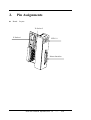
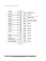
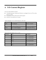
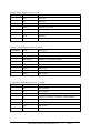
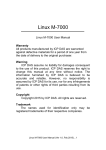
I-8072
User’s Manual
Warranty
All products manufactured by ICP DAS are warranted against defective
materials for a period of one year from the date of delivery to the original purchaser.
Warning
ICP DAS assume no liability for damages consequent to the use of this
product. ICP DAS reserves the right to change this manual at any time without
notice. The information furnished by ICP DAS is believed to be accurate and
reliable. However, no responsibility is assumed by ICP DAS for its use, nor for any
infringements of patents or other rights of third parties resulting from its use.
Copyright
Copyright 2002 by ICP DAS. All rights are reserved.
Trademark
The names used for identification only maybe registered trademarks of their
respective companies.
8072 User’s Manual, Sep/2002, Rev. 1.0
------
1/15
1.
General Introduction
The key component of 8072
1. A parallel printer interface
2. Two X-Sockets
3. Eight LED Indicators
Note: the 8072 can be installed to slot_0, 1, 2, and 4,5,6,7. It can not be installed in the slot_3.
1. A parallel printer interface
It can be used to link to dot-matrix printer or laser printer
The software support text mode only.
The source code of driver is open for user’s modification
User can modify the given driver to support graphic mode of his special printer
2. Two X-Sockets
These 2 X-Sockets can support S256 / S512 & AsicKey.
The X-Socket does not support Flash memory, 8073 supports flash memory solution.
User can install two S256 or one S256 & one AsicKey
User can install two S512 or one S512 & one AsicKey
The software driver for AsicKey is only open for AsicKey user.
3. Eight LED Indicators:
No pre-defined definition
User can use all of these 8 LEDs based on his special requirements
4. S256 and S512 can be installed to 8072 or back plane of 8000 (refer to Sec. 9.9.4 of
“8410/8411/8810/8811 User’s Manual”). The library is different. For S256 and S512 in 8072,
refer to cd/napdos/8000/common/minios7/demo/bc/8072/*.*
Or refer to our FTP site:
ftp://ftp.icpdas.com/pub/cd/8000cd/napdos/8000/common/minios7/demo/bc/8072/
8072 User’s Manual, Sep/2002, Rev. 1.0
------
2/15
2.
Pin Assignments
Board
Layout
X-Socket 2
X-Socket 1
LED * 8
Printer Interface
8072 User’s Manual, Sep/2002, Rev. 1.0
------
3/15
Pin Assignment of printer port
Strobe
1
2
3
4
5
6
7
8
9
Data 0
Data 1
Data 2
Data 3
Data 4
Data 5
Data 6
Data 7
Ack
14
15
16
17
Auto Feed
/Error
/Init Printer
/Deselect Printer
18
GND
19
GND
20
GND
21
GND
22
GND
23
GND
24
GND
25
GND
10
/Busy
11
Paper Out
Printer Online
12
13
8072 User’s Manual, Sep/2002, Rev. 1.0
------
4/15
3. Software Driver
Init8072
•
Description :
This subroutine will detect & Initialize the installed 8072 module.
•
Syntax :
WORD Init8072 (WORD SlotNum);
•
Parameter :
SlotNum : [Input] Slot Number. From 0 ~ 7
(Note: the 8072 can not be installed to slot_3)
•
Return:
0: One 8072 is detected & initialized
1: SlotNum error, must from 0 to 7
2: Read ID Error, can not find an 8072 in this slot
•
Note:
1. Call this function, Init8072 (SlotNum), before calling the other 8072 functions.
8072 User’s Manual, Sep/2002, Rev. 1.0
------
5/15
ShowLed8072
•
Description :
Write to LED.
•
Syntax :
WORD ShowLed8072 (WORD SlotNum, WORD LedValue);
•
Parameter :
SlotNum : [Input] Slot Number. From 0 ~ 7
(Note: the 8072 can not be installed to slot_3)
LedValue: [Input] write value of LED, from 0x00 to 0xff
•
Return:
0: Write OK
1: SlotNum error, must from 0 to 7
3: no 8072 initialization
•
Note:
1. Call Init8072 (SlotNum) before calling this function
8072 User’s Manual, Sep/2002, Rev. 1.0
------
6/15
ResetPrinter8072
•
Description :
Send a low pulse to pin 16, /Init Printer, of printer. It can be used to reset this printer.
•
Syntax :
WORD ResetPrinter8072 (WORD SlotNum);
•
Parameter :
SlotNum : [Input] Slot Number. From 0 ~ 7
(Note: the 8072 can not be installed to slot_3)
•
Return:
0: Write OK
1: SlotNum error, must from 0 to 7
3: no 8072 initialization
•
Note:
1. Call Init8072 (SlotNum) before calling this function
8072 User’s Manual, Sep/2002, Rev. 1.0
------
7/15
ReadPrinterStatus8072
•
Description :
Read the status byte of printer.
•
Syntax :
WORD ReadPrinterStatus8072 (WORD SlotNum, WORD *Status);
•
Parameter :
SlotNum : [Input] Slot Number. From 0 ~ 7
(Note: the 8072 can not be installed to slot_3)
Status: [Input] address of status byte
•
Return:
0: Write OK
1: SlotNum error, must from 0 to 7
3: no 8072 initialization
•
Note:
1. Call Init8072 (SlotNum) before calling this function
Pin definitions of Printer Status Register (status byte)
Bit Number
Name
Description
0
N/A
Reserved
1
N/A
Reserved
2
N/A
Reserved
3
/Error
Normal=1, no error
4
PrinterOnline
Normal=1, printer is online
5
Paper Out
Normal=0, printer has paper
6
ACK
Normal=1
7
/Busy
Normal=1, printer not busy
8072 User’s Manual, Sep/2002, Rev. 1.0
------
8/15
PrintChar8072
•
Description :
Print out one character.
•
Syntax :
WORD PrintChar8072 (WORD SlotNum, char ch);
•
Parameter :
SlotNum : [Input] Slot Number. From 0 ~ 7
(Note: the 8072 can not be installed to slot_3)
ch: [Input] value to print
•
Return:
0: Write OK
1: SlotNum error, must from 0 to 7
3: no 8072 initialization
•
Note:
1. Call Init8072 (SlotNum) before calling this function
8072 User’s Manual, Sep/2002, Rev. 1.0
------
9/15
PrintStr8072
•
Description :
Print out a string of characters.
•
Syntax :
WORD PrintStr8072 (WORD SlotNum, char szBuf []);
•
Parameter :
SlotNum : [Input] Slot Number. From 0 ~ 7
(Note: the 8072 can not be installed to slot_3)
szBuf: [Input] starting address of character string
•
Return:
0: Write OK
1: SlotNum error, must from 0 to 7
3: no 8072 initialization
•
Note:
1. Call Init8072 (SlotNum) before calling this function
8072 User’s Manual, Sep/2002, Rev. 1.0
------
10/15
ReadSramByte8072
•
Description :
Read one byte of S256 installed in the X-Socket of 8072.
Read one byte of S512 installed in the X-Socket of 8072.
•
Syntax :
WORD ReadSramByte8072 (WORD SlotNum, WORD U1U2,
DWORD Address, char *ch);
•
Parameter :
SlotNum : [Input] Slot Number. From 0 ~ 7
(Note: the 8072 can not be installed to slot_3)
U1U2: [Input] U1U2=1=X_Socket1, U1U2=2=X_Socket2
Address: [Input] address of byte to read, from 0x00 to 0x3ffff for S256
Address: [Input] address of byte to read, from 0x00 to 0x7ffff for S512
ch: address of read data
•
Return:
0: Write OK
1: SlotNum error, must from 0 to 7
3: no 8072 initialization
•
Note:
1. Call Init8072 (SlotNum) before calling this function
8072 User’s Manual, Sep/2002, Rev. 1.0
------
11/15
WriteSramByte8072
•
Description :
Write one byte to S256 installed in the X-Socket of 8072.
Write one byte to S512 installed in the X-Socket of 8072.
•
Syntax :
WORD WriteSramByte8072 (WORD SlotNum, WORD U1U2,
DWORD Address, char ch);
•
Parameter :
SlotNum : [Input] Slot Number. From 0 ~ 7
(Note: the 8072 can not be installed to slot_3)
U1U2: [Input] U1U2=1=X_Socket1, U1U2=2=X_Socket2
Address: [Input] address of byte to read, from 0x00 to 0x3ffff for S256
Address: [Input] address of byte to read, from 0x00 to 0x7ffff for S512
ch: data to write
•
Return:
0: Write OK
1: SlotNum error, must from 0 to 7
3: no 8072 initialization
•
Note:
1. Call Init8072 (SlotNum) before calling this function
8072 User’s Manual, Sep/2002, Rev. 1.0
------
12/15
ReadSramStatus8072
•
Description :
Read the status byte of S256 installed in the X-Socket of 8072.
Read the status byte of S512 installed in the X-Socket of 8072.
•
Syntax :
WORD ReadSramStatus8072 (WORD SlotNum, WORD U1U2, char *ch);
•
Parameter :
SlotNum : [Input] Slot Number. From 0 ~ 7
(Note: the 8072 can not be installed to slot_3)
U1U2: [Input] U1U2=1=X_Socket1, U1U2=2=X_Socket2
ch: address of status byte
•
Return:
0: Write OK
1: SlotNum error, must from 0 to 7
3: no 8072 initialization
•
Note:
1. Call Init8072 (SlotNum) before calling this function
Pin definitions of Printer Status Register (status byte)
Bit Number
Name
Description
0
Battery status
0=Low Battery, 1= High Battery
1
S256 or S512
0=S256,
2~7
N/A
Reserved
2=S512
8072 User’s Manual, Sep/2002, Rev. 1.0
------
13/15
4. I/O Control Register
Use Ti1 to Select Printer/X_Socket
The addressing space of printer & X-Socket is overlapped. So we use Ti1 to select
printer/X_Socket
SetTi1High select printer & I/O control register
SetTi1Low read/write to X_Socket
Address Mapping of I/O Controller Register (8-bit wide)
Offset Address Name
Description
0, read
Card ID Register
For 8072, it is 0x30
4, write
Printer Write Data Register
write data to printer
5, read
Printer Status Register
Read the status of printer
6, write
Printer Controller Register
Control printer & LED
7. write
X_Socket Control Register
Control X_Socket & LED
Printer Write Data Register, base+4, writes
Bit Number
Name
Description
0
Data_0
Bit_0 of printed data
1
Data_1
Bit_1 of printed data
2
Data_2
Bit_2 of printed data
3
Data_3
Bit_3 of printed data
4
Data_4
Bit_4 of printed data
5
Data_5
Bit_5 of printed data
6
Data_6
Bit_6 of printed data
7
Data_7
Bit_7 of printed data
8072 User’s Manual, Sep/2002, Rev. 1.0
------
14/15
Printer Status Register, base+5, read
Bit Number
Name
Description
0
N/A
Reserved
1
N/A
Reserved
2
N/A
Reserved
3
/Error
Normal=1, no error
4
PrinterOnline
Normal=1, printer is online
5
Paper Out
Normal=0, printer has paper
6
ACK
Normal=1
7
/Busy
Normal=1, printer not busy
Printer Control Register, base+6, writes
Bit Number
Name
Description
0
Strobe
Normal=0, 1=send one byte to printer
1
Auto Feed
Normal=0, 1=automatic line feed after CR
2
/Init Printer
Normal=1, 0=initialize printer
3
/Deselect Printer Normal=1, 0=deselect printer
4
LED5
Send to led
5
LED6
Send to led
6
LED7
Send to led
7
LED8
Send to led
X_Socket Control Register, base+7, writes
Bit Number
Name
Description
0
A9
To X_Socket
1
A12
To X_Socket
2
S0
0=select X_Socket_1, S0 & S1 can not both 0
3
S1
0=select X_Socket_2, S0 & S1 can not both 0
4
LED1
Send to led
5
LED2
Send to led
6
LED3
Send to led
7
LED4
Send to led
8072 User’s Manual, Sep/2002, Rev. 1.0
------
15/15